set clock DATSUN 210 1979 Service Manual
[x] Cancel search | Manufacturer: DATSUN, Model Year: 1979, Model line: 210, Model: DATSUN 210 1979Pages: 548, PDF Size: 28.66 MB
Page 22 of 548
SO
B
T
D
C
650
rpm
Non
California
models
except
Canada
100
B
T
0
C
650
rpm
Canada
models
Note
On
FU
models
ignition
timing
t
under
a
con4ition
where
distnoutor
vacuum
hose
is
discon
nected
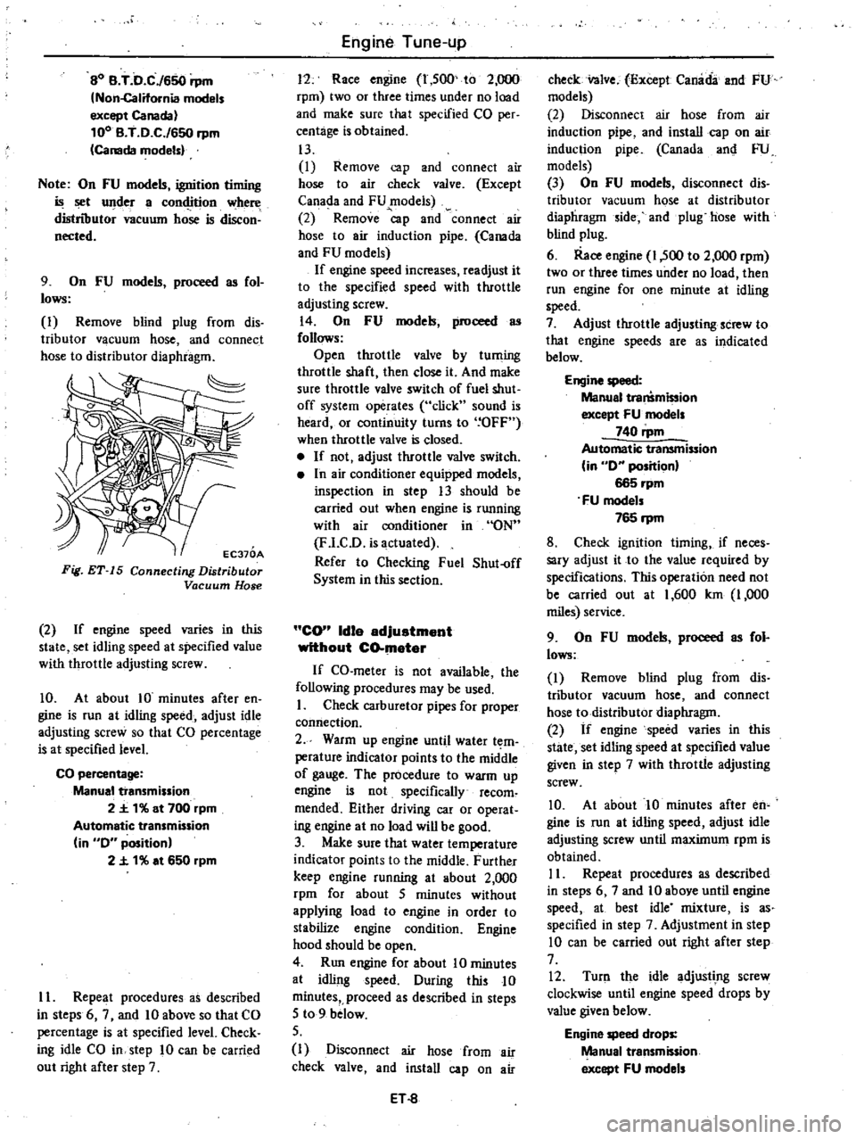
9
On
FU
models
proceed
as
fol
lows
I
Remove
blind
plug
from
dis
tributor
vacuum
hose
and
connect
hose
to
distributor
diaphragm
EC370A
Fig
ET
15
Connecting
Distributor
Vacuum
Hose
2
If
engine
speed
varies
in
this
state
set
idling
speed
at
specified
value
with
throttle
adjusting
screw
10
At
about
10
minutes
after
en
gine
is
run
at
idling
speed
adjust
idle
adjusting
screw
so
that
CO
percentage
is
at
specified
level
CO
percentage
Manual
transmission
2
t
1
at
700
rpm
Automatic
transmission
in
0
position
2
t
1
at
650
rpm
II
Repeat
procedures
as
described
in
steps
6
7
and
10
above
so
that
CO
percentage
is
at
specified
level
Check
ing
idle
CO
in
step
10
can
be
carried
out
right
after
step
7
Engine
Tune
up
11
Race
engine
1
500
to
2
000
rpm
two
or
three
times
under
no
load
and
make
sure
that
specified
CO
per
centage
is
obtained
13
I
Remove
cap
and
connect
air
hose
to
air
check
valve
Except
Canada
and
FU
models
2
Remove
p
and
connect
air
hose
to
air
induction
pipe
Canada
and
FU
models
If
engine
speed
increases
readjust
it
to
the
specified
speed
with
throttle
adjusting
screw
14
On
FU
models
proceed
as
follows
Open
throttle
valve
by
tuming
throttle
shaft
then
close
it
And
make
sure
throttle
valve
switch
of
fuel
shut
off
system
operates
click
sound
is
heard
or
continuity
turns
to
OFF
when
throttle
valve
is
closed
If
not
adjust
throttle
valve
switch
In
air
conditioner
equipped
models
inspection
in
step
13
should
be
carried
out
when
engine
is
running
with
air
conditioner
in
ON
F
l
CD
is
actuated
Refer
to
Checking
Fuel
Shut
off
System
in
this
section
CO
Idle
adjuatment
without
CO
mater
If
CO
meter
is
not
available
the
following
procedures
may
be
used
I
Check
carburetor
pipes
for
proper
comiection
2
Warm
up
engine
until
water
t
m
perature
indicator
points
to
the
middle
of
gauge
The
procedure
to
warm
up
engine
is
not
specifically
recom
mended
Either
driving
car
or
operat
ing
engine
at
no
load
will
be
good
3
Make
sure
that
water
temperature
indicator
points
to
the
middle
Further
keep
engine
running
at
about
2
000
rpm
for
about
5
minutes
without
applying
load
to
engine
in
order
to
stabilize
engine
condition
Engine
hood
should
be
open
4
Run
engine
for
about
10
minutes
at
idling
speed
During
this
10
minutes
proceed
as
described
in
steps
5
to
9
below
5
I
Disconnect
air
hose
from
air
check
valve
and
install
cap
on
air
ET
8
check
nlve
Except
Canada
and
FU
models
2
Disconnect
air
hose
from
air
induction
pipe
and
install
cap
on
air
induction
pipe
Canada
an
FU
models
3
On
FU
models
disconnect
dis
tributor
vacuum
hose
at
distributor
diaphragm
ide
and
plug
hose
with
blind
plug
6
Race
engine
1
500
to
2
000
rpm
two
or
three
times
under
no
load
then
run
engine
for
one
minute
at
idling
speed
7
Adjust
throttle
adjusting
screw
to
that
engine
speeds
are
as
indicated
below
Engine
speed
Manual
tra
mi
ion
except
FU
models
740
rpm
Automatic
transmission
in
0
position
665
rpm
FU
models
765
rpm
8
Check
ignition
timing
if
neces
sary
adjust
it
to
the
value
required
by
specifications
This
operation
need
not
be
carried
out
at
1
600
km
1
000
miles
service
9
On
FU
models
proceed
as
fol
lows
I
Remove
blind
plug
from
dis
tributor
vacuum
hose
and
connect
hose
to
distributor
diaphragm
2
If
engine
speed
varies
in
this
state
set
idling
speed
at
specified
value
given
in
step
7
with
throttle
adjusting
screw
10
At
about
10
minutes
after
en
gine
is
run
at
idling
speed
adjust
idle
adjusting
screw
until
maximum
rpm
is
obtained
II
Repeat
procedures
as
described
in
steps
6
7
and
10
above
until
engine
speed
at
best
idle
mixture
is
as
specified
in
step
7
Adjustment
in
step
10
can
be
carried
out
right
after
step
7
12
Turn
the
idle
adjustIng
screw
clockwise
until
engine
speed
drops
by
value
given
below
Engine
speed
drops
Manual
transmission
except
FU
models
Page 80 of 548
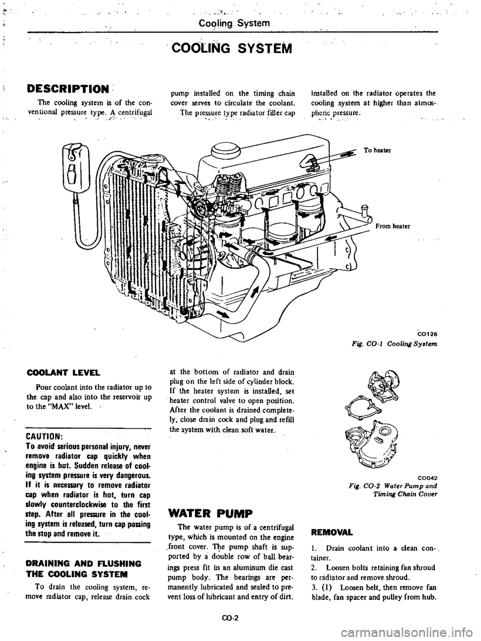
DESCRIPTION
The
cooling
system
is
of
the
con
ventional
pressure
type
A
centrifugal
1P
a
COOLANT
LEVEL
Pour
coolant
into
the
radiator
up
to
the
cap
and
also
into
the
reservoir
up
to
the
MAX
level
CAUTION
To
avoid
serious
personal
injury
never
remove
radiator
cap
quickly
when
engine
is
hot
Sudden
release
of
cool
ing
system
pressure
is
very
dangerous
If
it
is
necessary
to
remove
radiator
cap
when
radiator
is
hot
turn
cap
slowly
counterclockwise
to
the
first
step
After
all
pressure
in
the
cool
ing
system
is
released
turn
cap
passing
the
stop
and
remove
it
DRAINING
AND
FLUSHING
THE
COOLING
SYSTEM
To
drain
the
cooling
system
re
move
radiator
cap
release
drain
cock
C09ling
System
COOLING
SYSTEM
pump
installed
on
the
timing
chain
cover
serves
to
circulate
the
coolant
The
pressure
t
pe
radiator
filler
cap
at
the
bottom
of
radiator
and
drain
plug
on
the
left
side
of
cylinder
block
If
the
heater
system
is
instaDed
set
heater
control
valve
to
open
position
Mter
the
coolant
is
drained
complete
ly
close
drain
cock
and
plug
and
refdl
the
system
with
clean
soft
water
WATER
PUMP
The
water
pump
is
of
a
centrifugal
type
which
is
mounted
on
the
engine
front
cover
TJ
te
pump
shaft
is
sup
ported
by
a
double
row
of
baD
bear
ings
press
fit
in
an
aluminum
die
cast
pump
body
The
bearings
are
per
manently
lubricated
and
sealed
to
pre
vent
loss
of
lubricant
and
entry
of
dirt
CO
2
installed
on
the
radiator
operates
the
cooling
system
at
higher
than
atmos
pheric
pressure
To
heater
From
heater
C0126
Fig
COol
Cooling
System
C0042
Fig
CO
2
Water
Pump
and
Timing
Chain
Couer
REMOVAL
1
Drain
coolant
into
a
clean
con
tainer
2
Loosen
bolts
retaining
fan
shroud
to
radiator
and
remove
shroud
3
I
Loosen
belt
then
remove
fan
blade
fan
spacer
and
pulley
from
hub
Page 105 of 548
EF053A
Fig
EF
50
Removing
JWrneu
of
Solenoid
valve
2
Connect
rubber
hose
between
vacuum
gauge
and
intake
manifold
Note
A
quick
response
type
boost
gauge
such
as
Bourdon
s
type
is
recommended
a
mercury
type
manometer
should
not
be
used
3
Warm
up
engine
until
it
reaches
operating
temperature
Then
confirm
that
engine
idling
speed
is
specified
valve
Engine
idling
speed
Manual
transmission
700
rpm
Engine
Fuel
Automatic
transmission
in
0
position
650rpm
Note
On
automatic
transmission
models
never
race
engine
when
gearshift
lever
is
in
0
position
4
Run
engine
under
no
load
In
crease
engine
speed
to
3
000
to
3
500
rpm
then
quickly
close
throttle
valve
S
At
the
time
manifold
vacuum
pressure
increases
abruptly
to
600
rnmHg
23
6
inHg
or
above
and
then
gradually
decreases
to
the
level
set
at
idling
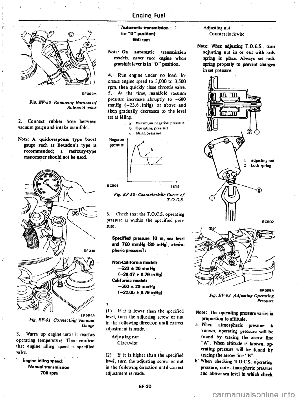
a
Maximum
negative
pressure
b
Operating
pressure
c
Idling
pressure
Nega
ive
pressure
EC502
Time
Fig
EF
52
Characteristic
Curve
of
T
O
C
S
6
Check
that
the
T
O
C
s
operating
pressure
is
within
the
specified
pres
sure
Specified
pressure
0
m
sea
level
end
760
mmHg
30
inHgl
atmOs
pheric
pressure
Non
Califomia
models
520
20
mmHg
20
47
0
79
inHg
California
models
560
20
mmHg
22
05
9
79
inHgl
7
I
If
it
is
lower
than
the
specified
level
turn
the
adjusting
screw
or
nut
in
the
following
direction
until
correct
adjustment
is
made
Adjusting
nut
Clockwise
2
If
it
is
higher
than
the
specified
levei
turn
the
adjusting
screw
or
nut
in
the
following
direction
until
correct
adjustment
is
made
EF
20
Adjusting
nut
Counterclockwise
Note
When
adjusting
T
O
C
S
turn
adjusting
nut
in
or
out
with
lock
spring
in
place
Always
set
lock
spring
properly
to
prevent
changes
in
set
pressure
Vo
1
Adjusting
nut
2
Lock
spring
n
EC802
EF055A
Fig
EF
53
Adjusting
Ope
llting
Pre
3ure
Note
The
operating
pressure
varies
in
proportion
to
altitude
a
When
atmospheric
pressure
is
known
operating
pressure
will
be
found
by
tracing
the
arrow
line
A
When
altitude
is
known
op
erating
pressure
will
be
found
by
tracing
the
arrow
line
B
b
When
checking
T
O
C
S
operating
pressure
note
atmospheric
pressure
and
above
sea
level
in
which
check
Page 106 of 548

is
to
be
made
and
determine
set
pressure
by
the
information
fur
nished
For
example
if
above
sea
level
is
1
000
m
3
280
ft
operating
pres
sure
will
then
be
475
mmHg
18
7
inHg
on
non
California
models
or
495
mmHg
19
5
inHg
on
California
models
In
other
words
T
O
C
S
operates
at
475
mmHg
18
7
inHg
or
490
mmHg
19
3
inHg
8
Race
engine
and
check
for
adjust
ment
9
If
engine
speed
will
not
drop
to
idling
speed
when
checking
throttle
opener
operating
pressure
proceed
as
follows
I
Turn
adjusting
screw
counter
clockwise
so
that
throttle
opener
oper
ating
pressure
is
on
high
vacuum
side
Engine
Fuel
25
mmHg
0
98
inHg
away
from
the
specified
value
2
Turn
adjusting
screw
l
O
of
a
turn
clockwise
so
that
throttle
opener
oper
ating
pressure
drops
by
25
mmHg
0
98
inHg
10
If
throttle
opener
operating
pressure
cannot
be
observed
clearly
even
in
step
9
proceed
as
follows
I
Turn
adjusting
screw
counter
clockwise
so
that
tluottle
opener
oper
ating
pressure
is
on
high
vacuum
side
50
mmHg
1
97
inHg
away
from
mid
point
of
the
specified
range
2
Turn
adjusting
screw
l
of
a
turn
clockwise
Note
The
throttle
opener
operating
pressure
should
be
correctly
set
within
the
specified
range
after
the
above
adju
stments
even
if
the
en
gine
speed
cannot
be
decreased
to
idling
inHg
mmHg
30
750
29
28
24
A
600
700
23
27
560
26
22
550
650
21
25
0
0
20
24
500
600
0
0
19
23
c
o
c
22
ii
18
0
0
450
550
E
c
0
17
2
16
20
400
500
15
B
Non
California
model
350
14
California
model
13
300
5
000
6
000
1ft
0
1
000
2
000
3
001
4
000
0
0
5
1
5
2
km
Altitude
EF056A
Fig
EF
54
Clumges
in
Operating
Pressure
Versus
Changes
in
Atmospheric
Pressure
EF
21
SERVO
DIAPHRAGM
STROKE
I
Connect
engine
tachometer
2
Warm
up
engine
until
it
reaches
operating
temperature
3
Disconnect
rubber
hose
between
servo
diaphragm
and
vacuum
control
valve
Then
connect
rubber
hose
to
in
take
manifold
Servo
diaphragm
Rubber
hose
T
O
C
S
solenoid
valve
T
O
C
S
control
valve
EF250
EF057A
Fig
EF
55
Connecting
Rubber
Hose
to
Intake
Manifold
4
Servo
diaphragm
is
functioning
properly
if
engine
speed
comes
into
the
specified
range
Specified
engine
speed
1
650
to
1
850
rpm
except
Californial
1
900
to
2
100
rpm
for
California
5
If
necessary
adjust
engine
speed
until
it
is
in
the
specified
range
using
servo
diaphragm
adjusting
screw
When
engine
speed
is
lower
than
the
prescribed
range
Turn
adjusting
screw
clockwise
When
engine
speed
is
higher
than
the
prescribed
range
Turn
adjusting
screw
counterclockwise
Page 221 of 548
DISASSEMBLY
TRANSMISSION
CASE
DISASSEMBLY
I
Prior
to
disassembling
traiIsmis
sian
thoroughly
wipe
off
dirt
and
grease
from
it
2
Drain
oil
thoroughly
3
Remove
dust
cover
from
trans
mission
case
Remove
release
bearing
and
with
drawallever
4
Remove
reverse
lamp
switch
and
top
detecting
switch
if
equipped
5
Remove
speedometer
pinion
as
sembly
6
Remove
nut
and
stopper
pin
bolt
from
rear
end
of
rear
extension
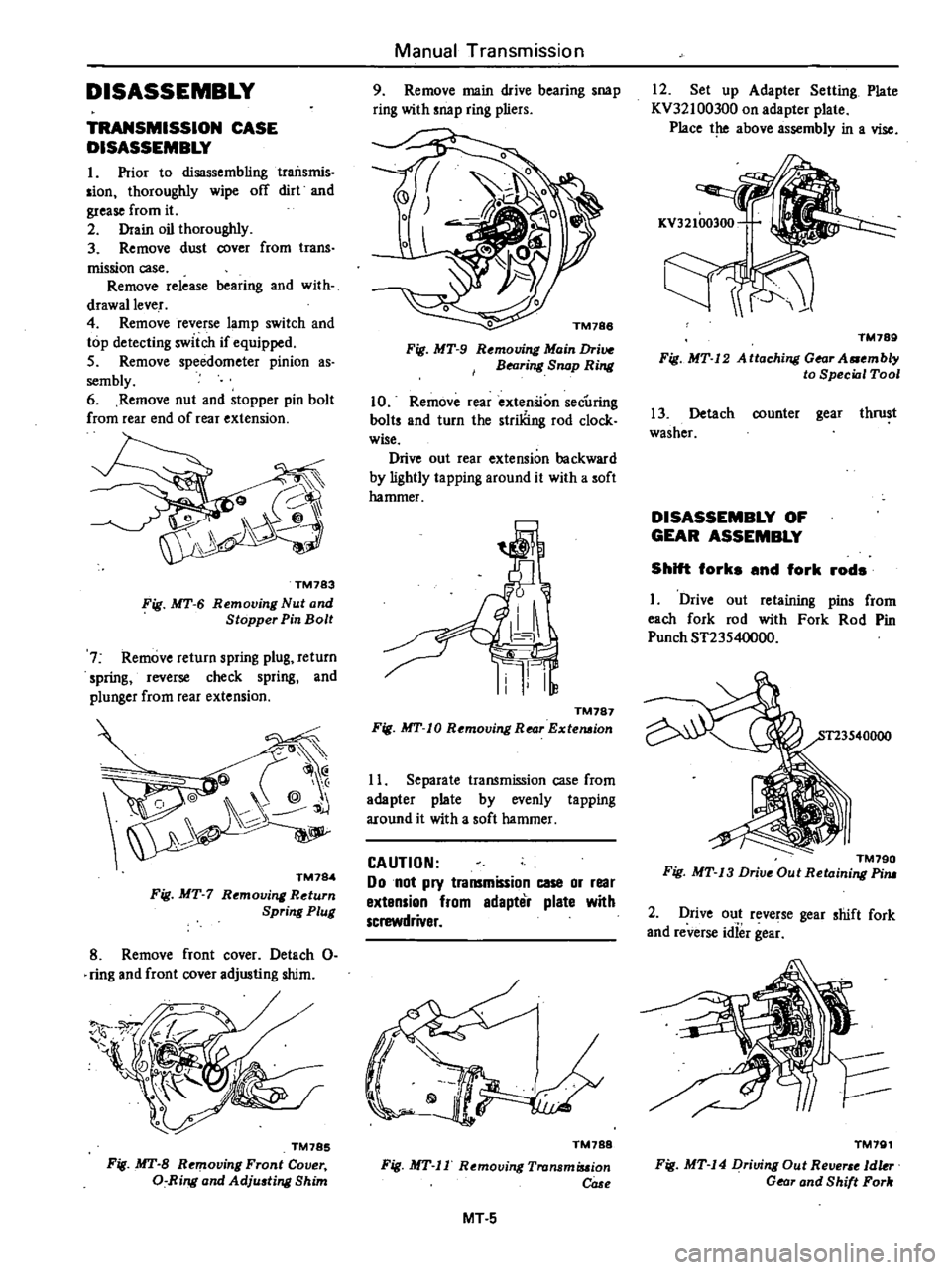
TM783
Fig
MT
6
Removing
Nut
and
Stopper
Pin
Bolt
7
Remove
return
spring
plug
return
spring
reverse
check
spring
and
plunger
from
rear
extension
@
@
j
TM784
Fig
MT
7
Rt
moving
Return
Spring
Plug
8
Remove
front
cover
Detach
0
ring
and
front
cover
adjusting
shim
TM785
Fig
MT
B
Removing
Front
Cover
a
Ring
and
Adju
ting
Shim
Manual
Transmission
9
Remove
main
drive
bearing
snap
ring
with
snap
ring
pliers
o
TM188
Fig
MT
9
Rt
mouing
Main
Drive
BNring
Snap
Ring
10
Remove
rear
extenSion
secUring
baits
and
turn
the
striliing
rod
clock
wise
Drive
out
rear
extension
backward
by
lightly
ta
pping
around
it
with
a
soft
hammer
TM787
Fig
MT
10
Removing
Rear
Extemion
11
Separate
transmission
case
from
adapter
plate
by
evenly
tapping
around
it
with
a
soft
hammer
CAUTION
Do
not
pry
transmission
case
or
rear
extension
from
edapter
plate
with
screwdriver
TM788
Fig
MT
II
Removing
Tronsmiuion
COSf
MT
5
12
Set
up
Adapter
Setting
Plate
KV32100300
on
adapter
plate
Place
the
above
assembly
in
a
vise
TM789
Fig
MT
12
A
ttaching
Gear
A
mbly
to
Special
Tool
13
Detach
counter
gear
thrust
washer
DISASSEMBLY
OF
GEAR
ASSEMBLY
Shift
forks
and
fork
rods
I
Drive
out
retaining
pins
from
each
fork
rod
with
Fork
Rod
Pin
Punch
ST23540000
TM790
Fig
MT
13
Drive
Out
Retaining
Pim
2
Drive
out
reverse
gear
shift
fork
and
reverse
idief
gea
TM791
Fig
MT
14
Driving
Out
Re
1dkr
Gear
and
Shift
Fork
Page 230 of 548
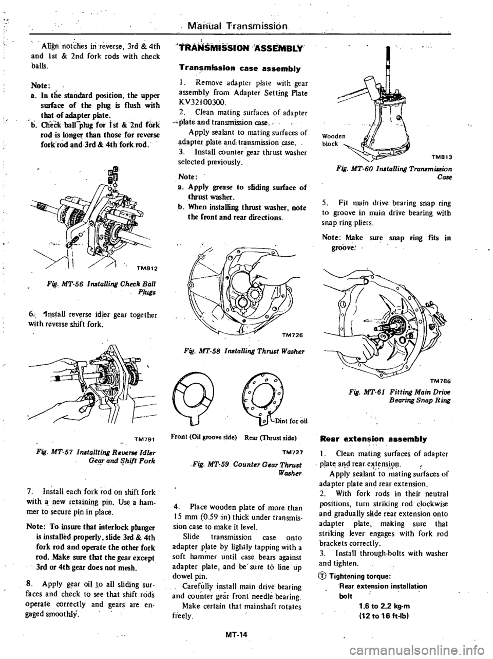
Align
notches
in
reverse
3rd
4th
and
1st
2nd
fork
rods
with
check
balls
Note
a
In
the
standard
position
the
upper
surface
of
the
ping
is
nush
with
thaI
of
adapter
plate
b
CheCk
balfpIug
for
i
st
2nd
fork
rod
is
longer
than
those
for
reverse
forkrod
and
3rd
4th
fork
rod
Manual
Transmission
TRANS
SSION
ASSEMBLY
Transmission
case
assembly
Remove
adapter
plale
with
gear
assembly
from
Adapter
Setting
Plate
KV32100300
2
Clean
mating
surfaces
of
adapter
plate
and
transmission
case
Apply
sealant
to
mating
surfaces
of
adapter
plate
3
nd
transmission
case
3
Install
counter
gear
thrust
washer
selected
previously
Note
a
Apply
grease
to
stiding
sorface
of
thrust
washer
b
When
installing
thrust
washer
note
the
front
and
rear
directions
Fig
MT
56
Installing
Check
Ball
0
Plugs
6
1nstall
rev
rse
idler
gear
together
with
reverse
shift
fork
TM791
Fig
MT
57
Installting
Re
ldler
Getg
and
Shift
Fork
7
Install
each
fork
rod
on
shift
fork
with
new
retainif
g
pin
U
a
ham
mer
toseCUfe
pin
in
place
Note
To
insure
that
interlock
plunger
is
installed
properly
slide
3rd
4th
fork
rod
and
operate
the
other
fork
rod
Make
sure
that
the
gear
except
lrd
or
4th
gear
does
not
mesh
8
Apply
g
ar
oil
o
all
sliding
sur
faces
and
check
to
see
that
shift
rods
operate
correctly
and
gears
are
en
gaged
smoothly
Fig
MT
58
Installing
Thrust
Washer
Front
Oil
groove
side
Rear
Thrust
side
TM727
Fig
MT
59
Counter
Gear
Thru
t
Washt
r
4
Place
wooden
plate
of
more
than
15
mm
0
59
in
thick
under
transmis
sion
case
to
make
it
level
Slide
transmission
case
onto
adapter
plate
by
lightly
tapping
with
a
soft
hammer
until
case
bears
against
adapter
plate
and
be
sure
to
line
up
dowel
pin
Carefully
install
main
drive
bearing
and
counter
gear
front
needle
bearing
Make
certain
that
rnainshaft
rotates
freely
MT14
1
Wooden
block
TM813
Fig
MT
60
Installing
Transmiuion
Cale
5
Fit
main
drive
bearing
snap
ring
to
groove
in
main
drive
bearing
with
snap
ring
pliers
Note
Make
sure
snap
ring
fits
in
groove
Fig
MT
61
Fitting
Main
Dri
Bearing
Snap
Ring
Rear
extension
assembly
Clean
mating
surfaces
of
adapter
p
Iat
aIld
rear
e
tens
i91
Apply
sealant
to
mating
surfaces
of
adapter
plate
and
rear
extension
2
With
fork
rods
in
their
neutral
positions
turn
striking
rod
clockwise
and
gradually
slide
rear
extension
onto
adapter
plate
making
sure
that
striking
lever
engages
with
fork
rod
brackets
correctly
3
Install
through
bolts
with
washer
and
tighten
b
Tightening
torque
Rear
extension
installation
bolt
1
6
to
2
2
kg
m
12
to
16
ft
lb
Page 235 of 548
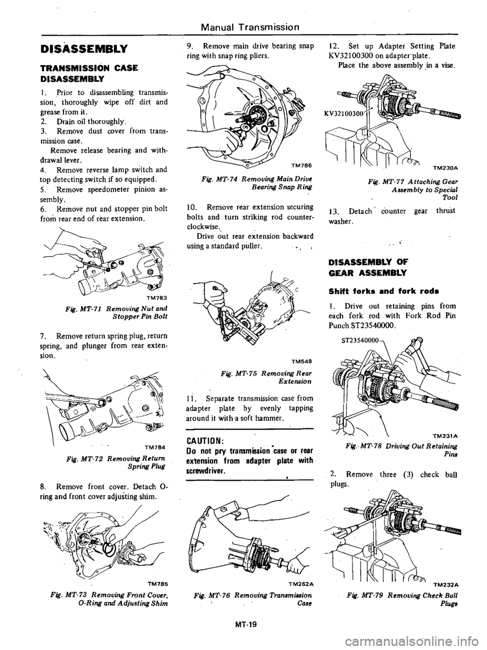
DISASSEMBLY
TRANSMISSION
CASE
DISASSEMBLY
1
Prior
to
disassembling
transmis
sion
thoroughly
wipe
off
dirt
and
grease
from
it
2
Drain
oil
thoroughly
3
Remove
dust
cover
from
trans
mission
case
Remove
release
bearing
and
with
drawallever
4
Remove
reverse
lamp
switch
and
top
detecting
switch
if
so
equipped
5
Remove
speedometer
pinion
as
sembly
6
Remove
nut
and
stopper
pin
bolt
from
rear
end
of
rear
extension
Fig
MT
71
Removing
Nut
and
Stopper
Pin
Bolt
7
Remove
return
spring
plug
return
spring
and
plunger
from
rear
exten
sion
@
@
Q
@
j
TM784
Fig
MT
72
Removing
Return
Spring
Plug
8
Remove
front
cover
Detach
0
ring
and
front
cover
adjusting
shim
1l
l
TM785
Fig
MT
73
Removing
Front
Cover
D
Ring
and
Adju
ting
Shim
Manual
Transmission
9
Remove
main
drive
bearing
snap
ring
with
snap
ring
pliers
Fig
MT
74
Removing
Main
Drive
Bearing
Snap
Ring
10
Remove
rear
extension
securing
bolts
and
turn
striking
rod
counter
clockwise
Drive
out
rear
extension
backward
using
a
standard
puller
TM548
Fig
MT
75
Removing
R
ar
Extension
11
Separate
transmission
case
from
adapter
plate
by
evenly
tapping
around
it
with
a
soft
hammer
CAUTION
00
not
pry
transmission
case
or
rear
extension
from
adapter
plate
with
screwdriver
TM262A
Fig
MT
76
Removing
Tran
miuion
Ca
e
MT19
12
Set
up
Adapter
Setting
Plate
KV32100300
on
adapter
plate
Place
the
above
assembly
in
a
vise
TM230A
Fig
MT
77
A
ttaching
Gear
Assembly
to
Special
Tool
13
Detach
counter
gear
thrust
washer
DISASSEMBLY
OF
GEAR
ASSEMBLY
Shift
forks
and
fork
rods
1
Drive
out
retaining
pins
from
each
fork
rod
with
Fork
Rod
Pin
Punch
ST23540000
TM231
A
Fig
MT
78
Driving
Out
Retaining
Pim
2
Remove
three
3
check
ball
plugs
TM232A
Fig
MT
79
Removing
Check
Ball
Plug
Page 245 of 548
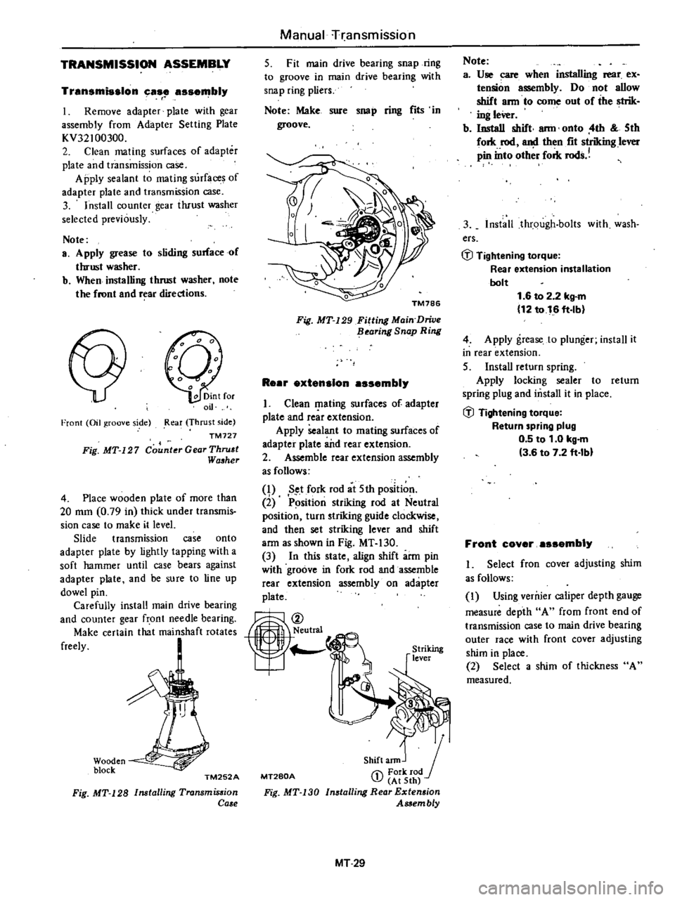
TRANSMISSION
ASSEMBLY
Transmission
case
assembly
r
I
Remove
adapter
plate
with
gear
assembly
from
Adapter
Setting
Plate
KV32100300
2
Clean
mating
surfaces
of
adapter
plate
and
transmission
case
Apply
sealant
to
mating
surfaces
of
adapter
plate
and
transmission
case
3
Install
counter
gear
tluust
washer
selected
previously
Note
a
Apply
grease
to
sliding
surface
of
thrust
washer
b
When
installing
thrust
washer
note
the
front
and
r
ar
directions
Front
Oil
groove
side
Rear
Thrust
side
TM727
Fig
MT
127
Counter
Gear
Thru
t
Wa
her
4
Place
wooden
plate
of
more
than
20
mm
0
79
in
thick
under
transmis
sion
case
to
make
it
level
Slide
transmission
case
onto
adapter
plate
by
lightly
tapping
with
a
soft
hammer
until
case
bears
against
adapter
plate
and
be
sure
to
line
up
dowel
pin
Carefully
install
main
drive
bearing
and
counter
gear
front
needle
bearing
Make
certain
that
mainshaft
rotates
freely
Wooden
block
TM252A
Fig
MT
128
Installing
Transmis
ion
Ca
e
Manual
rransmission
5
Fit
main
drive
bearing
snap
ring
to
groove
in
main
drive
bearing
with
snap
ring
pliers
Note
Make
sure
sno
p
ring
fits
in
groove
Fig
MT
129
Fitting
Main
Drive
flearing
Snap
Ring
ReBr
extension
assembly
I
Clean
I
lating
surfaces
of
adapter
plate
and
rcar
extension
Apply
sealant
to
mating
surfaces
of
adapter
plate
a
itd
rear
extension
2
Assemble
rear
extension
assembly
as
follows
q
Set
fork
rod
at
5th
position
2
P
sition
striking
rod
at
Neutral
position
turn
striking
guide
clockwise
and
then
set
striking
lever
and
shift
arm
as
shown
in
Fig
MT
130
3
In
this
state
align
shift
arm
pin
with
groove
in
fork
rod
and
assemble
rear
extension
assembly
on
adapter
plate
MT280A
Shift
ann
J
1
Fork
rod
J
At
5th
Installing
Rear
Extension
Assembly
Fig
MT
130
MT29
Note
a
Use
care
when
installing
rear
ex
tension
assembly
Do
not
allow
shift
ann
to
come
out
of
the
strik
ing
leVer
b
Install
shift
ann
onto
4th
5th
fork
rod
and
then
fit
striking
lever
pin
into
oth
r
fork
rods
3
Install
through
bolts
with
wash
ers
GJ
Tightening
torque
Rear
extension
installation
bolt
1
6
to
2
2
kg
m
12
to
16
ft
lb
4
Apply
grease
to
plunger
install
it
in
rear
extension
5
InstaU
return
spring
Apply
locking
sealer
to
return
spring
plug
and
mstall
it
in
place
GJ
Tightening
torque
Return
spring
plug
0
5
to
1
0
kg
m
3
6
to
7
2
ft
lbl
Front
coyer
assembly
I
Select
fron
cover
adjusting
shim
as
follows
I
Using
verruer
caliper
depth
gauge
measure
depth
A
from
front
end
of
transmission
case
to
main
drive
bearing
outer
race
with
front
cover
adjusting
shim
in
place
2
Select
a
shim
of
thickness
A
measured
Page 260 of 548
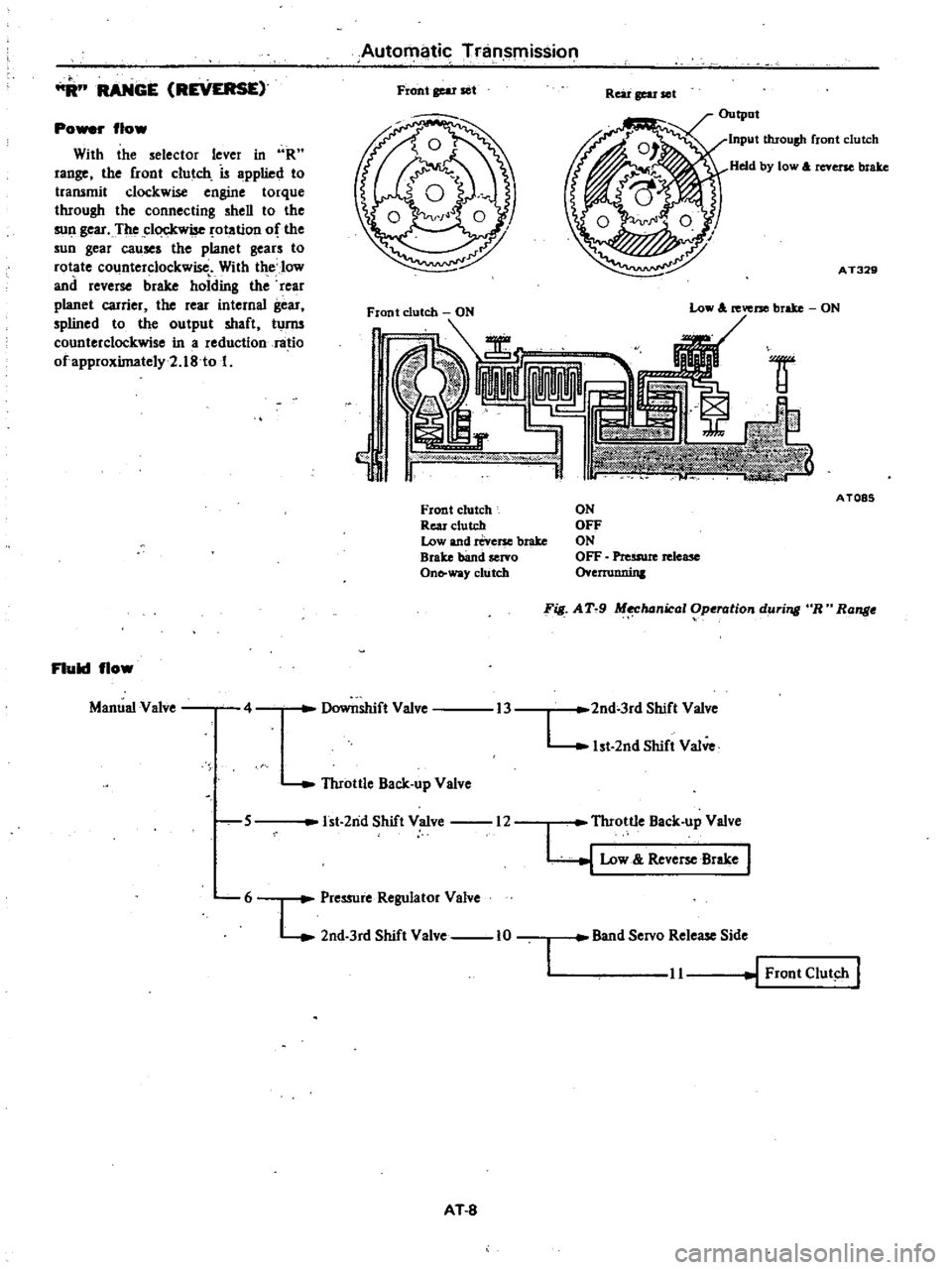
RANGE
REVERSE
Po
r
flow
With
the
selector
lever
in
R
range
the
front
clutch
is
applied
to
transmit
clockwise
engine
torque
through
the
connecting
shell
to
the
sull
gear
The
clockwise
otation
of
the
sun
gear
causes
the
planet
gears
to
rotate
counterclockwise
With
the
low
and
reverse
brake
holding
the
rear
planet
carrier
the
rear
internal
gear
splined
to
the
output
shaft
turm
counterclockwise
in
a
reduction
ratio
ofapproximately2
18
to
1
Fluid
flow
Manual
Valve
4
Automatic
Tninsmission
Front
gear
set
Rear
gear
ell
Output
Input
throush
front
clutch
Held
by
low
A
reverse
brake
AT329
lW
w
Y
Front
clutch
Rear
clutch
Low
and
reverse
brake
Brake
band
servo
On
way
clutch
5
Throttle
Back
up
Valve
Low
A
reverse
brake
ON
Downshift
Valve
1st
2nd
Shift
Valve
12
6
L
Pressure
Regulator
Valve
2nd
3rd
Shift
Valve
10
AT
8
AT085
ON
OFF
ON
OFF
Preuwe
release
o
ernmnin
F
AT
9
M
hanical
Operation
during
R
Range
13
2nd
3rd
Shift
Valve
L
1st
2nd
Shift
Valve
I
Throttle
Back
up
Valve
y
Low
Reve
Brake
Band
Servo
Release
Side
11
Front
Clut
h
I
Page 264 of 548
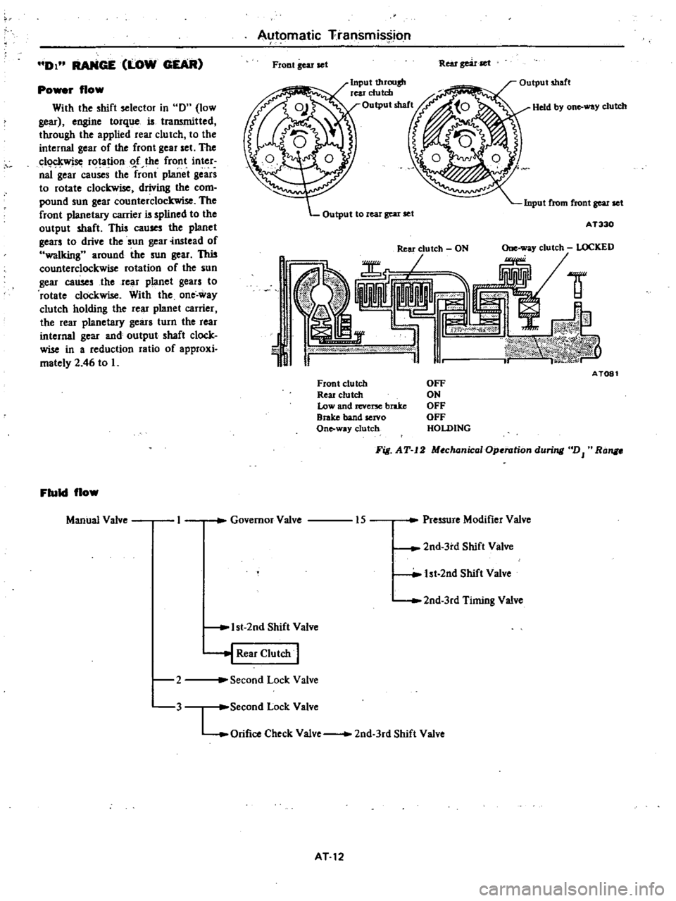
DI
RANGE
LOW
GEAR
Po
r
flow
With
the
shift
selector
in
0
low
gear
engine
torque
is
traJWnitted
through
the
applied
rear
clu
tch
to
the
internal
gear
of
the
front
gear
set
The
c1o
kwise
rotation
o
f
the
front
inter
naI
gear
causes
the
front
planet
gears
to
rotate
clockwise
driving
the
com
pound
sun
gear
counterclockwise
The
front
planetary
carrier
is
splined
to
the
output
shaft
This
cau
the
planet
gears
to
drive
the
sun
gear
instead
of
walking
around
the
sun
gear
This
counterclockwise
rotation
of
the
sun
gear
causes
the
rear
planet
gears
to
rotate
clockwise
With
the
one
way
clutch
holding
the
rear
planet
carrier
the
rear
planetary
gears
turn
the
rear
internal
gear
and
output
shaft
clock
wise
in
a
reduction
ratio
of
approxi
mately
2
46
to
L
Fluid
flow
Manual
Valve
2
3
Automatic
Transmission
Fiont
gear
set
Rear
gear
set
Input
t1uOllsh
rear
clutch
Output
shaft
Held
by
on
way
clutch
Input
from
front
gear
set
Output
to
real
gear
set
AT330
1
J
ld
AT081
Front
clutch
Reu
clutch
Low
and
revcrx
brake
Brake
band
servo
Onto
way
clutch
OFF
ON
OFF
OFF
HOLDING
Fig
AT
12
MochanicaIOp
rationduri
DJ
Ra
Governor
Valve
Pressure
Modifier
Valve
15
2nd
3rd
Shift
Valve
lst
2nd
Shift
Valve
2nd
3rd
Timing
Valve
1st
2nd
Shift
Valve
j
Rear
Clutch
I
Second
Lock
Valve
Second
Lock
Valve
LOrifice
Check
Valve
2nd
3rd
Shift
Valve
AT12