warning light DATSUN 210 1979 User Guide
[x] Cancel search | Manufacturer: DATSUN, Model Year: 1979, Model line: 210, Model: DATSUN 210 1979Pages: 548, PDF Size: 28.66 MB
Page 460 of 548

CHARGE
WARNING
SYSTEM
Refer
to
Section
EE
BRAKE
WARNING
SYSTEM
REPLACEMENT
Hand
brake
switch
I
Disconnect
battery
ground
cable
2
Remove
console
box
if
equipped
3
Disconnect
hand
brake
switch
lead
wire
at
connector
4
Remove
switch
from
switch
bracket
by
pulling
it
5
Install
new
switch
in
the
reverse
order
of
removal
BE
177C
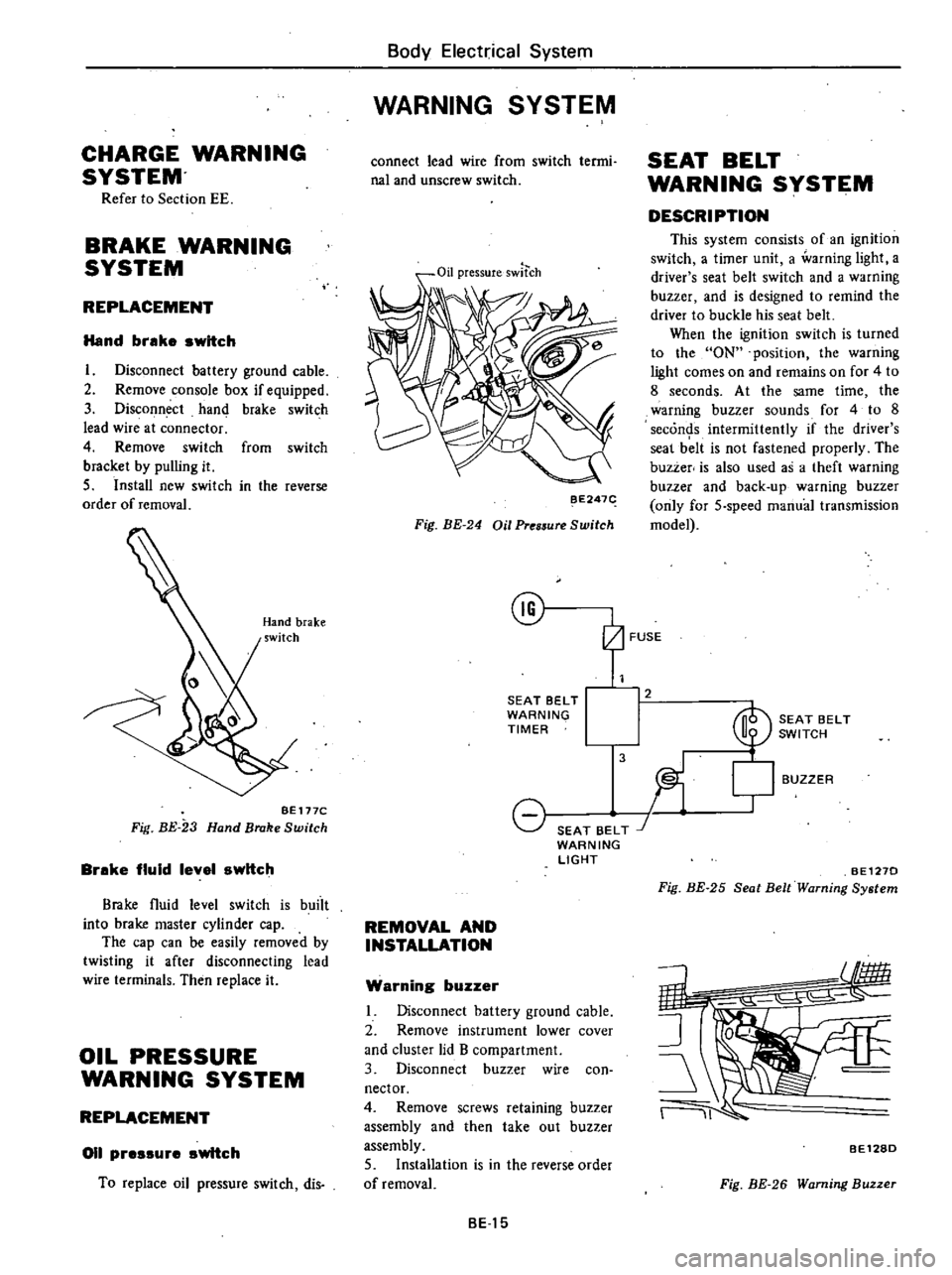
Fig
BE
23
Hand
Brake
Switch
Brake
fluid
level
switch
Brake
fluid
level
switch
is
buiit
into
brake
master
cylinder
cap
The
cap
can
be
easily
removed
by
twisting
it
after
disconnecting
lead
wire
terminals
Then
replace
it
OIL
PRESSURE
WARNING
SYSTEM
REPLACEMENT
011
pressure
switch
To
replace
oil
pressure
switch
dis
Body
Electrical
System
WARNING
SYSTEM
connect
lead
wire
from
switch
termi
nal
and
unscrew
switch
Oil
pressureswltch
BE247
Fig
BE
24
Oil
Pres5ure
Switch
@
SEAT
BELT
WARNING
TIMER
8
SEAT
BELT
J
WARNING
LIGHT
REMOVAL
AND
INSTALLATION
Warning
buzzer
Disconnect
battery
ground
cable
2
Remove
instrument
lower
cover
and
cluster
lid
B
compartment
3
Disconnect
buzzer
wire
con
nector
4
Remove
screws
retaining
buzzer
assembly
and
then
take
out
buzzer
assembly
5
Installation
is
in
the
reverse
order
of
removal
BE15
SEAT
BELT
WARNING
SYSTEM
DESCRIPTION
This
system
consists
of
an
ignition
switch
a
timer
unit
a
warning
light
a
driver
s
seat
belt
switch
and
a
warning
buzzer
and
is
designed
to
remind
the
driver
to
buckle
his
seat
belt
When
the
ignition
switch
is
turned
to
the
ON
position
the
warning
light
comes
on
and
remains
on
for
4
to
8
seconds
At
the
same
time
the
warning
buzzer
sounds
for
4
to
8
seconds
intermittently
if
the
driver
s
seal
b
lt
is
not
fastened
properly
The
buzzer
is
also
used
as
a
theft
warning
buzzer
and
back
up
warning
buzzer
only
for
5
speed
manual
transmission
model
2
3
BUZZER
SEAT
BELT
SWITCH
l
BE1270
Fig
BE
25
Seat
Belt
Warning
System
11
BE128D
Fig
BE
26
Warning
Buzzer
Page 475 of 548

WIPER
MOTOR
WINDSHIELD
WASHER
MOTOR
REAR
WIPER
MOTOR
REAR
WINDOW
WASHER
MOTOR
m
w
o
HORN
CIGARETTE
LIGHTER
CLOCK
HAZARD
FLASHER
LAMP
STOP
LAMP
ROOM
LAMP
LUGGAGE
ROOM
LAMP
TAIL
LAMP
CLEARANCE
LAMP
LICENSE
PLATE
LAMP
COMBINATION
METER
LAMP
l
I
ll
6
C
l
ii
en
g
0
o
m
till
oill
l
I
t1
l
CO
l
m
l
m
0
z
t
15A
10A
14
fA
20A
16
T
r
t1
l
t1
l
CO
CO
CJ
CJ
1
1
m
m
0
0
z
z
HEATER
lAIR
CONDITIONER
ENGINE
REVOLUTION
SWITCH
FUEL
CUT
SOLENOID
VACUUM
CUT
SOLENOID
AUTO
CHOKE
HEATER
THROTTLE
OPENER
SOLENOID
TURN
SIGNAL
LAMP
GAUGE
I
FUEL
L
WATER
TEMPERATURE
WARNING
LAMP
BRAKE
CHARGE
OIL
PRESSURE
SEAT
BELT
WARNING
BUZZER
BACK
UP
LAMP
KICKDOWN
SOLENOID
TACHOMETER
REAR
DEFOGGER
f
c
It
1
1
m
g
II
n
a
n
c
It
c
1J
c
CIl
z
G
S
3
OJ
o
Cl
m
CD
In
Ql
Page 484 of 548

Body
Electrical
System
Turn
signsl
snd
hszsrd
wsrnlng
Ismp
Condition
Turn
signals
do
not
operate
Hazard
warning
lamps
oper
te
Haza
d
warning
lamps
do
not
operate
Turn
signals
operate
No
flasher
click
is
heard
Flashing
cycle
is
too
slow
Pilot
lamp
does
not
go
out
or
too
fast
Flashing
cycle
is
irregular
Stop
Ismp
Condition
Neither
left
nor
right
lamp
lights
Lamp
on
only
one
side
lights
Probable
cause
Burnt
fuse
Loose
connection
or
open
circuit
Faulty
flasher
unit
Faulty
turn
signal
switch
Faulty
hazard
switch
Turn
signals
operate
when
CD
and
i
terminals
of
harness
connector
to
hazard
switch
are
connected
with
test
lead
including
l5A
fuse
Burnt
fuse
Faulty
hazard
warning
flasher
unit
Faulty
hazard
switch
Left
Right
side
lamps
operate
when
@
and
@
@
and
@
terminals
of
harness
connector
to
hazard
switch
are
connected
with
test
lead
including
l5A
fuse
Burnt
bulb
Loose
connection
Bulb
other
than
specified
wattage
being
used
Burnt
bulbs
Loose
connection
Faulty
flasher
unit
Burnt
bulb
Loose
coimection
Bulbs
other
than
specified
wattage
being
used
Probable
cause
Burnt
fuse
Faulty
stop
switch
Loose
connection
or
open
circuit
Burnt
bulb
Loose
bulb
Loose
connection
or
open
circuit
BE
39
Corrective
action
Correct
cause
and
replace
Check
wiring
and
or
repair
connection
Replace
Conduct
continuity
test
and
replace
if
neces
sary
Re
place
if
necessary
Correct
cause
and
replace
Replace
Replace
if
necessary
Replace
Reconnect
firmly
Replace
with
one
specified
Replace
Repair
Replace
Replace
Repair
Replace
with
one
specified
Corrective
action
Correct
cause
and
replace
Conduct
continuity
test
and
replace
if
neces
sary
Check
wiring
and
or
repair
connection
Replace
Repair
lamp
socket
Check
wiring
nd
or
repair
connection
Page 491 of 548

Body
Electrical
Sy
tem
Oil
pr
re
charg
and
brake
warillng
Condition
Lamp
does
not
glow
when
ignition
switch
is
turned
ON
with
out
running
engine
Door
and
charge
warning
lamps
do
not
go
out
when
engine
is
started
Charge
waming
amp
Lamp
does
not
go
out
when
engine
is
started
Oil
pressure
warning
lamp
Lamp
does
not
light
when
ignition
switch
is
set
to
ON
Lamp
does
not
go
out
while
engine
is
being
operated
Brake
warning
lamp
Lamp
does
not
go
out
Door
warning
lamp
Lamp
does
not
glow
with
door
opened
and
engine
running
Probable
cause
Burnt
bulb
or
loo
ebulb
Loose
or
poor
connection
Faully
bulb
check
relay
or
alternator
Faully
charging
system
Faully
oil
pressure
switch
or
loose
switch
terminal
connection
When
lead
wire
connected
to
switch
is
grounded
warning
lamp
lights
Lack
of
engine
oil
Oil
pressure
too
low
Faully
oil
pressure
switch
Faulty
hand
brake
switch
When
hand
brake
lever
is
released
Faully
brake
fluid
level
switch
When
brake
fluid
level
is
normal
Faully
door
switch
BE
46
Corrective
action
Replace
bulb
or
correct
Correct
connector
terminal
contacts
Correct
adjust
or
replace
Inspect
charging
system
Replace
or
correct
connection
Check
oil
level
and
add
oil
as
required
Inspect
engine
oil
pressure
system
Replace
Replace
Replace
Replace
Page 512 of 548

Air
Conditioning
6
Loosen
the
connection
at
the
center
fitting
of
manifold
gauge
for
a
Clockwise
few
seconds
to
purge
air
inside
charg
ing
hose
See
Fig
AC
14
Counterclockwise
j
3
@
I
Can
tap
handle
2
ChlcginS
hose
3
Needle
4
Refrigerant
can
AC246
Fig
AC
13
Can
Top
Purging
air
R
12
To
L9w
pressure
service
valve
AC247
Fig
AC
14
Purging
Air
Ta
High
pressure
service
valve
f
r
AC181A
Fig
AC
15
Discharging
System
AC
ll
DISCHARGING
SYSTEM
The
pressurized
refrigerant
gas
in
side
system
must
be
discharged
to
a
pressure
approaching
atmospheric
pressure
prior
to
evacuating
refrigerant
inside
system
This
operation
should
be
also
made
to
pennit
safe
removal
when
replacing
system
components
A
Close
high
and
low
pressure
valves
of
manifold
gauge
fully
2
Connect
two
charging
hoses
of
manifold
gauge
to
their
respective
service
valves
WARNING
Securely
connect
high
pressure
dis
charge
service
valve
to
that
of
manifold
gauge
with
a
hose
also
connect
low
pressure
suction
serv
ice
valve
to
that
of
manifold
gauge
For
locations
of
high
and
low
pres
sure
discharge
and
suction
service
valves
see
Fig
AC
29
3
Open
both
manifold
gauge
valves
slightly
and
slowly
discharge
refriger
ant
from
system
See
Fig
AC
15
WARNING
Protect
fingers
with
cloth
against
frostbite
by
refrigerant
when
con
necting
the
charging
hose
to
the
service
valve
or
disconnecting
it
therefrom
Nole
Do
not
allow
refrigerant
to
rush
out
Otherwise
compressor
oil
will
be
discharged
along
with
refriger
ant
EVACUATING
SYSTEM
I
Connect
high
and
low
pressure
charging
hoses
of
manifold
gauge
to
their
respective
service
valves
of
sys
tem
and
discharge
refrigerant
from
system
Refer
to
Discharging
System
WARNING
Securely
connect
high
pressure
dis
charge
service
valve
to
that
of
manifold
gauge
with
a
hose
also
connect
low
pressure
suction
servo
ice
valve
to
that
of
manifold
gauge
For
locations
of
high
and
low
pres
sure
discharge
and
wction
service
valves
see
Fig
AC
29
Page 516 of 548

HALIDE
LEAK
DETECTOR
Since
the
propane
leak
detector
and
butane
leak
detector
are
the
same
in
respect
to
their
operation
this
section
describes
the
operation
of
the
propane
leak
detector
The
copper
screen
is
heated
by
the
Air
Conditioning
burning
of
propane
Refrigerant
gas
decomposes
to
color
the
flame
when
it
contacts
the
heated
screen
The
gas
to
be
checked
is
drawn
into
the
sampling
tube
and
sent
out
to
the
burner
A
refrigerant
leak
can
clearly
be
detected
by
variations
in
the
color
of
the
flame
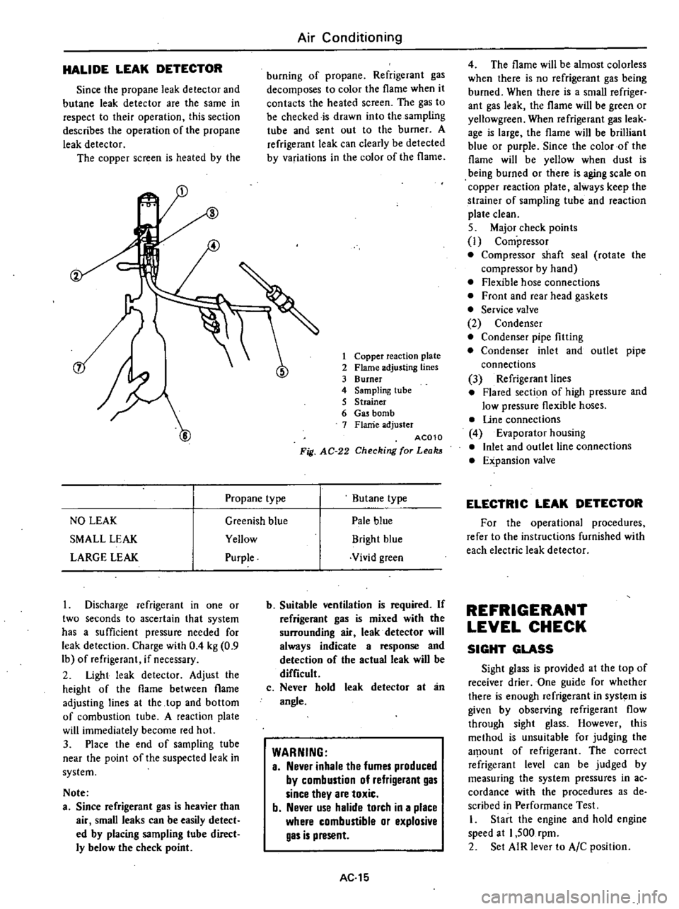
1
Copper
reaction
plate
2
Flame
adjusting
lines
3
Burner
4
Sampling
tube
5
Strainer
6
Gas
bomb
7
Flame
adjuster
AC010
Fig
AC
22
Checking
for
Leaks
4
The
flame
will
be
almost
colorless
when
there
is
no
refrigerant
gas
being
burned
When
there
is
a
small
refriger
ant
gas
leak
the
flame
will
be
green
or
yellowgreen
When
refrigerant
gas
leak
age
is
large
the
flame
will
be
brilliant
blue
or
purple
Since
the
color
of
the
flame
will
be
yellow
when
dust
is
being
burned
or
there
is
aging
scale
on
copper
reaction
plate
always
keep
the
strainer
of
sampling
tube
and
reaction
plate
clean
5
Major
check
points
l
Compressor
Compressor
shaft
seal
rotate
the
compressor
by
hand
Flexible
hose
connections
Front
and
rear
head
gaskets
Service
valve
2
Condenser
Condenser
pipe
fitting
Condenser
inlet
and
outlet
pipe
connections
3
Refrigerant
lines
Flared
section
of
high
pressure
and
low
pressure
flexible
hoses
Une
connections
4
Evaporator
housing
Inlet
and
outlet
line
connections
Expansion
valve
Propane
type
Butane
type
ELECTRIC
LEAK
DETECTOR
NO
LEAK
Greenish
blue
Pale
blue
For
the
operational
procedures
SMALL
LEAK
Yellow
Bright
blue
refer
to
the
instructions
furnished
with
LARGE
LEAK
Purple
Vivid
green
each
electric
leak
detector
Discharge
refrigerant
in
one
or
two
seconds
to
ascertain
that
system
has
a
sufficient
pressure
needed
for
leak
detection
Charge
with
0
4
kg
0
9
Ib
of
refrigeranl
if
necessary
2
Light
leak
detector
Adjust
the
height
of
the
flame
between
flame
adjusting
lines
at
the
top
and
bottom
of
combustion
tube
A
reaction
plate
will
immediately
become
red
hot
3
Place
the
end
of
sampling
tube
near
the
point
of
the
suspected
leak
in
system
Note
a
Since
refrigerant
gas
is
heavier
than
air
small
leaks
can
be
easily
detect
ed
by
placing
sampling
tube
direct
ly
below
the
check
point
b
Suitable
ventilation
is
required
If
refrigerant
gas
is
mixed
with
the
surrounding
air
leak
detector
will
always
indicate
a
response
and
detection
of
the
actual
leak
will
be
difficult
c
Never
hold
leak
detector
at
an
angle
WARNING
a
Never
inhale
the
fumes
produced
by
combustion
of
refrigerant
gas
since
they
are
toxic
b
Never
use
halide
torch
in
a
place
where
combustible
or
explosive
gas
is
present
AC
15
REFRIGERANT
LEVEL
CHECK
SIGHT
GLASS
Sight
glass
is
provided
at
the
top
of
receiver
drier
One
guide
for
whether
there
is
enough
refrigerant
in
syst
m
is
given
by
observing
refrigerant
flow
through
sight
glass
However
this
method
is
unsuitable
for
judging
the
aJTlount
of
refrigerant
The
correct
refrigeranl
level
can
be
judged
by
measuring
the
system
pressures
in
ac
cordance
with
the
procedures
as
de
scribed
in
Performance
Test
1
Start
the
engine
and
hold
engine
speed
al
1
500
rpm
2
Set
AIR
lever
to
AlC
position