high DATSUN 210 1979 Owner's Guide
[x] Cancel search | Manufacturer: DATSUN, Model Year: 1979, Model line: 210, Model: DATSUN 210 1979Pages: 548, PDF Size: 28.66 MB
Page 130 of 548
Emission
Control
System
r
@
@
CD
L
I
1
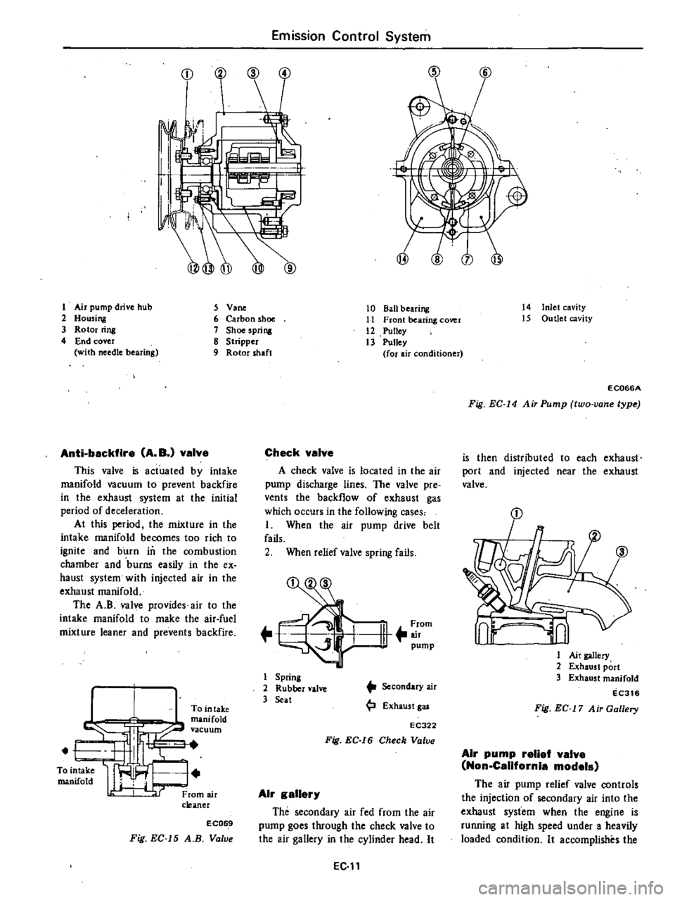
Air
pump
drive
hub
5
V
ne
2
Housing
6
Carbon
shoe
3
Rotor
rins
7
Shoe
spri
ng
4
End
cover
8
Stripper
with
needle
bearing
9
Rotor
shaft
Anti
backfire
A
B
valve
This
valve
is
actuated
by
intake
manifold
vacuum
to
prevent
backfire
in
the
exhaust
system
at
the
initial
period
of
deceleration
At
this
period
the
mixture
in
the
intake
manifold
becomes
too
rich
to
ignite
and
burn
in
the
combustion
chamber
and
burns
easily
in
the
ex
haust
system
with
injected
air
in
the
exhaust
manifold
The
A
B
valve
provides
air
to
the
intake
manifold
to
make
the
air
fuel
mixture
leaner
and
prevents
backfire
To
in
take
manifold
vacuum
EC069
Fig
EC
15
A
B
Valve
10
Ball
bearing
11
Front
bearing
cOYer
12
Pulley
13
Pulley
for
air
conditioner
Check
valve
A
check
valve
is
located
in
the
air
pump
discharge
lines
The
valve
pre
vents
the
backflow
of
exhaust
gas
which
occurs
in
the
following
cases
I
When
the
air
pump
drive
belt
fails
2
When
relief
valve
spring
fails
1
11
rom
pump
1
Spring
2
Rubber
valve
3
Seat
SecondarY
air
4
J
Exhaust
gas
EC322
Fig
EC
16
Check
Valve
Air
gallery
The
secondary
air
fed
from
the
air
pump
goes
through
the
check
valve
to
the
air
gallery
in
the
cylinder
head
It
EC
lt
14
Inlet
cavity
15
Outlet
cavity
EC066A
Fig
EC
14
Air
Pump
two
vane
lype
is
then
distributed
to
each
exhaust
port
and
injected
near
the
exhaust
valve
0
iJl
Ai
gallery
2
Exhaust
port
3
Exhaust
manifold
EC316
Fig
EC
17
Air
Gallery
Air
pump
relief
valve
Non
California
models
The
air
pump
relief
valve
controls
the
injection
of
secondary
air
into
the
exhaust
system
when
the
engine
is
running
at
high
speed
under
a
heavily
loaded
condition
It
accomplishes
the
Page 131 of 548

following
functions
without
affecting
the
effectiveness
of
the
exhaust
emis
sion
control
system
Minimizes
exhaust
gas
tempera
ture
rise
2
Minimizes
horsepower
losses
reo
sulting
from
air
injection
into
the
exhaust
system
3
Protects
pump
from
excessive
back
pressure
To
carburetor
air
cleaner
Secondary
ir
Not
actuated
To
carburetor
air
cleaner
J
l
Secondary
sir
Actuated
EC294
Fig
EC
18
Air
Pump
Relief
Valve
c
A
C
valve
Californiamodels
The
C
A
C
valve
controls
the
quantity
of
secondary
air
fed
from
the
air
pump
according
to
the
load
condi
tion
and
it
discharges
the
secondary
air
into
the
atmosphere
to
prevent
overheating
of
the
catalytic
converter
This
valve
is
operated
by
intake
manifold
vacuum
and
air
pump
dis
charge
pressure
When
intake
manifold
vacuum
is
small
or
in
the
high
load
range
the
No
2
valve
opens
when
it
is
great
or
in
the
low
load
range
the
No
I
valve
opens
If
air
pump
discharge
pressure
is
large
or
the
engine
is
running
at
a
high
speed
the
No
3
valve
opens
admitting
the
air
pump
discharge
pressure
to
the
No
2
dia
phragm
chamber
of
the
C
A
C
valve
mission
Control
System
and
opening
ihe
No
i
valve
At
this
point
the
No
2
valve
serves
as
a
relief
valve
F
111
air
pump
No
3
valve
EC787
Fig
EC
19
C
A
C
Valve
I
Engine
in
low
speed
and
light
load
When
the
engine
is
operating
under
these
conditions
intake
vacuum
is
high
The
No
2
valve
unitized
with
the
No
I
diaphragm
is
lifted
by
the
intake
manifold
vacuum
pushing
up
the
No
I
valve
These
valves
will
then
stop
at
a
position
where
a
balanced
condition
exists
between
air
pump
discharge
pressure
an
d
spring
tension
acting
on
the
No
I
and
No
2
valves
The
No
2
jiaphragm
however
does
not
move
due
to
low
engine
speed
low
air
pump
discharge
pressure
and
spring
tension
acting
on
the
No
3
valve
For
this
reason
these
valves
are
brought
to
a
balanced
condition
To
intake
manifold
t
i
l
3
Spring
4
ValveNo
3
5
Di
phragm
No
I
I
@
6
Spring
7
Valve
No
1
8
Valve
No
2
EC683
Fig
EC
20
Operation
of
C
A
C
Valve
1
2
Engine
in
low
speed
and
heavy
load
EC12
Wheo
the
engine
is
operating
under
these
cooditions
intake
manifold
vacuum
is
low
and
all
valves
are
balanced
t
To
intake
manUol
U
E
ii
ji
j
Ii
5
LL
jj
Ii
JI
l
Jij
ulJC
1t
To
atmosphere
EC685
Fig
EC
21
Operation
of
C
A
C
Valve
2
3
Engine
in
high
speed
and
middle
load
When
the
engine
is
operating
under
these
conditions
intake
manifold
vacuum
lies
midway
between
1
and
2
above
The
No
3
valve
moves
to
the
left
because
of
high
air
pump
discharge
pressure
To
intake
manifold
t
L
J
f
E
bt
I
5
tfi
11
I
LJr
To
tmg
J
j
1
EC
4
Fig
EC
22
Operation
of
C
A
C
Volve
3
REMOVAL
AND
INSTALLATION
Air
pump
air
cleaner
Loosen
nuts
securing
air
pump
air
cleaner
to
bracket
then
detach
air
cleaner
from
bracket
Air
cleaner
filter
and
air
cleaner
lower
body
are
built
into
a
unit
construction
Replace
air
cleaner
filter
and
lower
body
as
an
assembly
Page 135 of 548

them
b
If
carbon
shoes
are
exposed
beyond
the
rotor
end
face
remove
carbon
shoes
and
clean
shoe
grooves
Reas
semble
carbon
shoes
6
Vane
1
Pack
vane
bearing
with
high
melting
poinf
grease
MIL
G
3S45
A
Es
o
ANDOK260
or
equivalent
and
insert
dummy
shaft
into
the
vane
bearing
STl9900000
EC563
Fig
EC
40
Va
Assembly
2
Install
vane
in
place
on
rotor
uMng
Dummy
Shaft
STl9900000
as
a
guide
Note
The
woes
may
require
6
to
16
km
4
to
10
miles
wear
in
running
time
In
the
event
a
slight
squeaking
still
remains
drive
the
car
about
64
to
80
km
h
40
to
SO
MPH
In
most
cases
6
to
16
km
4
to
10
miles
will
be
sufficient
for
wear
in
7
Shoe
spring
Place
shoe
springs
in
deeper
groave
of
shoe
11
I
11
1
EC123
Fig
EC
4I
Ins
tolling
Shoe
Spring
Note
When
installing
a
shoe
spring
make
sure
that
the
outward
bend
ing
side
faces
in
shoe
and
that
both
ends
of
sJlri
face
in
the
wall
of
Emission
Control
System
shoe
groove
6e
Sure
to
push
spring
in
SO
that
spring
end
face
is
flush
with
rotor
8
Rotor
ring
Install
rotor
ring
by
correctly
align
ing
the
rear
end
face
of
rotor
with
the
on
mark
in
rotor
ring
and
tighten
screws
with
Hexagon
Wrench
ST
98
10000
l
l
Tightening
torque
Rotor
ring
screw
0
5
to
0
7
kg
m
13
6
to
5
1
ft
lb
Fig
EC
42
Installing
Rotor
Ring
9
Removal
of
dummy
shaft
CarefuDy
withdraw
dummy
shaft
from
vane
10
Vane
shaft
Pack
rear
bearing
with
high
melting
pain
t
grease
MIL
G
3S45
A
Esso
ANDOK
260
or
equivalent
Apply
thin
coating
of
grease
to
vane
shaft
and
rotor
ring
and
insert
vanf
shafi
into
its
bearing
Note
a
Do
not
apply
an
undue
stress
to
vane
shaft
when
inserting
b
If
two
vanes
are
dislocated
when
inserting
vane
shaft
correctly
align
Yanes
by
inserting
dummy
shaft
Then
draw
out
dummy
shaft
and
insert
vane
shaft
c
When
wear
occurs
on
vane
shaft
or
when
replacement
of
rear
bearing
is
necessary
replace
rear
rover
assem
bly
J
I
End
cover
Position
end
cover
in
place
Snugly
tighten
the
bolt
close
to
the
dowel
Then
tighten
end
cover
bolts
EC
t6
l
l
Tighteningtnrque
End
cover
bolts
0
7
to
0
9
kg
m
5
1
to
6
5
ft
bl
EC302
Fig
EC
43
lnstolling
End
Cover
12
Pulley
Tighten
pulley
securing
bolts
Tightening
torque
Pulley
securing
bolts
0
75
to
0
90
kg
m
5
4
to
6
5
ft
Ib
INSPECTION
The
following
procedures
are
re
commended
for
checking
and
or
as
certaining
that
the
various
components
of
the
exhaust
emission
control
system
are
opera
ting
properly
The
engine
and
all
components
mu
t
be
at
normal
operating
tempera
tures
when
the
tests
are
performed
Prior
to
performing
any
extensive
diag
nosis
of
the
exhaust
control
ystem
h
must
be
determined
that
the
engine
as
a
unit
is
functioning
properly
Air
injection
s
stem
hoses
Check
air
system
hoses
for
loose
connections
cracks
or
deterioration
Retighten
01
replace
if
necessary
Air
pump
I
Operate
engine
until
it
reaches
normal
operating
temperature
2
Inspect
all
hose
hose
connec
tions
and
air
gaDery
for
leaks
and
correct
if
necessary
before
checking
air
injection
pump
Page 138 of 548

Air
Induction
v
lve
filter
The
air
induction
valve
filter
is
installed
at
the
dust
side
of
the
air
cleaner
It
purifies
secondary
air
to
be
sent
to
the
exhaust
tube
The
fIlter
element
should
be
replaced
periodical
ly
in
accordance
with
the
Maintenance
Schedule
EC921
Fig
EC
54
Air
Induction
Valve
Filter
Antl
beckflre
v
lve
A
B
v
lve
Tltis
valve
is
controlled
by
intake
manifold
vacuum
to
prevent
backfire
in
the
exhaust
system
at
the
initial
period
of
deceleration
At
this
period
the
mixture
in
the
intake
manifold
becomes
too
rich
to
ignite
and
burn
in
the
combustion
chamber
and
burns
easily
in
the
ex
haust
system
with
injected
air
in
the
exhaust
manifold
The
anti
backfire
valve
provides
air
to
the
intake
manifold
to
make
the
air
fuel
mixture
leaner
and
prevents
backfire
If
the
valve
does
not
work
properly
unburned
ntixture
will
be
emitted
from
the
combustion
chambers
and
burns
with
the
aid
of
high
temperature
and
injected
air
which
causes
backfrre
To
intake
manifold
vacuum
To
intake
manifold
From
air
cleaner
EC069
Fig
EC
55
Anti
backfire
Value
Emission
Control
System
Air
Induction
Into
exhaust
port
The
secondary
air
fed
from
the
air
induction
valve
goes
through
the
check
valve
to
the
air
gallery
in
the
cylinder
head
It
is
then
distributed
to
each
exhaust
port
and
injected
near
the
exhaust
valve
I
Air
gallery
2
Exhaust
port
3
Exhaust
manifold
EC316
Fig
EC
56
Sectional
View
of
Exhaust
Port
REMOVAL
AND
INSTALLATION
Air
Induction
valve
and
filter
Remove
the
screws
securing
the
valve
and
filter
to
the
air
cleaner
body
The
air
induction
valve
and
valve
filter
can
then
be
taken
out
easily
Installa
tion
is
in
the
reverse
sequence
of
removal
EC922
Fig
EC
57
Removing
Air
Induction
Valve
and
Filter
EC
19
Air
Induction
pipe
Loosen
out
a
nut
securing
the
pipe
to
the
engine
cylinder
head
At
the
same
time
remove
the
screws
securing
the
bracket
and
rubber
hose
clamp
The
air
induction
pipe
can
then
be
taken
out
Installation
is
in
the
reverse
sequence
of
removal
Fig
EC
58
A
B
valve
The
A
B
valve
is
located
at
the
rear
side
of
the
air
cleaner
Remove
the
air
hoses
and
vacuum
tube
The
A
B
valve
can
then
be
taken
out
Installation
is
in
the
reverse
se
quence
of
removal
EC152A
Fig
EC
59
Removing
A
B
Valve
INSPECTION
Preliminary
Inspection
Check
hose
for
looseness
flatting
damage
or
faulty
connections
and
each
part
for
proper
installation
If
necessary
replace
Air
Induction
valve
and
filter
I
Disconnect
air
induction
hose
at
air
induction
pipe
side
Suck
or
blow
hose
to
make
sure
that
air
flows
only
on
the
air
induction
pipe
side
Page 144 of 548
INSPECTION
Entire
system
I
Make
a
thorough
vjsual
check
of
E
G
R
control
system
If
necessary
wipe
away
oil
to
facilitate
inspection
If
any
hoses
are
cracked
or
broken
replace
2
With
engine
stopped
inspect
E
G
R
control
valve
for
any
indication
of
binding
or
sticking
by
moving
dia
phragm
of
control
valve
upwards
with
a
finger
3
With
engine
running
inspect
E
G
R
control
valve
and
thermal
vacu
um
valve
for
normal
operation
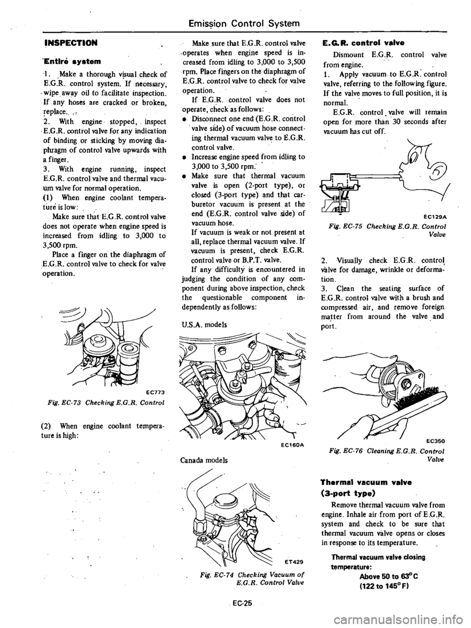
1
When
engine
coolant
tempera
tun
is
low
Make
sure
that
E
G
R
control
valve
does
not
operate
when
engine
speed
is
increased
from
idling
to
3
000
to
3
500
rpm
Place
a
finger
on
the
diaphragm
of
E
G
R
control
valve
to
check
for
valve
operation
EC773
Fig
EC
73
Checking
E
G
R
Control
2
When
engine
coolant
tempera
tureishigh
Emission
Control
System
Make
sure
that
E
G
R
control
valve
operates
when
engine
speed
is
in
creased
from
idling
to
3
000
to
3
500
rpm
Place
fingers
on
the
diaphragm
of
E
G
R
control
valve
to
check
for
valve
operation
If
E
G
R
control
valve
does
not
operate
check
as
follows
Disconnect
one
end
E
G
R
control
valve
side
of
vacuum
hose
connect
ing
ihermal
vacuum
valve
to
E
G
R
control
valve
Increase
engine
speed
from
idling
to
3
000
to
3
500
rpm
Make
sure
that
thermal
vacuum
valve
is
open
2
port
type
or
closed
3
port
type
and
that
car
buretor
vacuum
is
present
at
the
end
E
G
R
control
valve
side
of
vacuum
hose
If
vacuum
is
weak
or
not
present
at
all
replace
thermal
vacuum
valve
If
vacuum
is
present
check
E
G
R
control
valve
or
B
P
T
valve
If
any
difficulty
is
encountered
in
judging
the
condition
of
any
com
ponent
during
above
inspection
check
the
questionable
component
in
dependently
as
follows
U
S
A
models
Ie
EC160A
Canada
models
ET429
Fig
EC
74
Checking
Vacuum
of
E
G
R
Control
Valve
EC
25
E
G
R
control
valve
Dismount
E
G
R
control
valve
from
engine
I
Apply
vacuum
to
E
G
R
control
valve
referring
to
the
following
figure
If
the
valve
moves
to
full
position
it
is
normal
E
G
R
control
valve
will
remain
open
for
more
than
30
seconds
after
vacuum
has
cut
off
5t
orr
rl
1
1
Fig
EC
75
EC129A
Checking
E
G
R
Control
Valve
2
Visually
check
E
G
R
control
wive
for
damage
wrinkle
or
deforma
tion
3
Clean
the
seating
surface
of
E
G
R
control
valve
with
a
brush
and
compressed
air
and
remove
foreign
matter
from
around
the
valve
and
port
Fig
EC
76
Cleoning
E
G
R
Control
Valve
Thermal
vacuum
valve
3
port
type
Remove
thermal
vacuum
valve
from
engine
Inhale
air
from
port
ofE
G
R
system
and
check
to
be
sure
that
thermal
vacuum
valve
opens
or
closes
in
response
to
its
temperature
Thermal
vacuum
valve
dosing
temperature
Above
50
to
630
C
122
to
1450
F
Page 146 of 548
Emission
Control
System
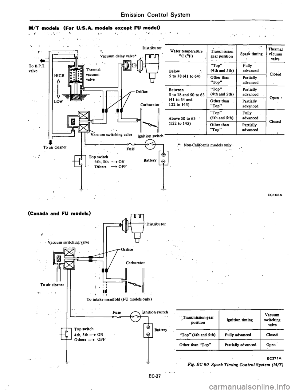
M
T
models
For
U
S
A
models
except
FU
model
Distributor
r
To
B
P
T
valve
HIGH
vacuum
valve
OrifiCO
i
jarburetor
l
Vacuum
switching
valve
Ignition
switch
I
To
air
cleaner
Fuse
8
Top
switch
4th
5th
Others
Battery
8
ON
OFF
Canada
and
FU
models
OM
1orifico
F
JCMburetor
To
air
cleaner
1
V
cuum
switching
valve
To
intake
manifold
FU
models
only
Fuse
G1j
Ignition
switch
Battery
7
EJ
Top
switch
4th
5th
ON
Others
OFF
EC
27
Water
temperature
OC
OF
Below
5
to
18
41
to
64
Between
I
5
to
18
and
50
t063
41
to
64
and
I
122
to
145
I
I
Above
50
to
63
122
to
145
Transmission
ear
position
Top
4th
and
5111
Other
than
Top
Top
4th
and
5th
Other
than
Top
Top
4th
and
5th
Other
than
Top
Non
California
models
only
Thermal
Spark
timing
vacuwn
valve
Fully
advanced
I
Closed
Partially
advanced
Partially
I
advanced
Partially
I
Open
ad
ced
Fully
I
advanced
I
Closed
Partially
advanced
EC162A
Transmission
gear
Vacuwn
Ignition
timing
switching
position
valve
Top
4th
and
5th
Fully
advanced
Closed
Other
than
Top
Partially
advanced
Open
EC371A
Fig
EC
BO
Spork
Timing
Control
Sy
tem
MIT
Page 148 of 548
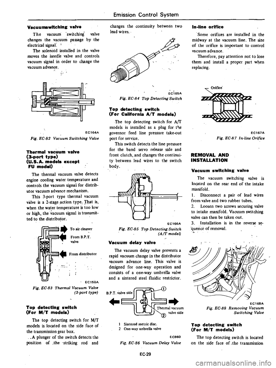
Vacuumswltching
valve
The
vacuum
switching
valve
changes
the
vacuum
passage
by
the
electrical
signa
The
solenoid
installed
in
the
valve
moves
the
needle
valve
and
controls
vacuum
signal
in
order
to
change
the
vacuum
advance
I
c
III
J
IL
jll
J
EC164A
Fig
EC
82
Vacuum
Switching
Valve
Thermal
vacuum
valve
3
port
type
U
S
A
modele
except
FU
model
The
thermal
vacuum
valve
detects
engine
cooling
water
temperature
and
controls
the
vacuum
signal
for
distrib
utor
vacuum
advance
mechanism
This
3
port
type
thermal
vacuum
valve
is
a
2
stage
action
type
That
is
when
the
water
temperature
is
too
low
or
high
the
acuum
signal
is
transmit
ted
to
the
distributor
ffi2
To
air
cleaner
From
B
PT
valve
From
distributor
EC156A
Fig
EC
83
Thermal
Vacuum
Valve
3
port
type
Top
detecting
switch
For
M
T
models
The
top
detecting
switch
for
M
T
models
is
located
on
the
side
face
of
the
transmission
gear
box
A
plunger
of
the
switch
detects
the
position
of
the
striking
rod
and
Emission
Control
System
changes
the
continuity
between
two
lead
wires
EC165A
Fig
EC
84
Top
Detecting
Switch
Top
detecting
switch
For
Celifornla
AfT
model
The
top
detecting
switch
for
Arr
models
is
installed
as
a
plug
for
t
e
governor
feed
line
pressure
take
out
port
for
service
This
switch
detects
the
line
pressure
for
the
band
servo
release
side
and
front
clutch
and
changes
the
continui
ty
between
lead
wires
to
the
switch
body
EC166A
Fig
EC
85
Top
Detecting
Switch
AfT
model
Vacuum
delay
valve
The
vacuum
delay
valve
prevents
a
rapid
vacuum
change
in
the
distributor
vacuum
advance
line
This
valve
is
designed
for
one
way
operation
and
consists
of
a
one
way
umbrella
valve
and
a
sintered
steel
fluidic
restrictor
B
P
T
valve
side
J
l
1
Sintered
metric
disc
2
One
way
unbreUa
valve
EC860
Fig
EC
86
Vacuum
Delay
Value
EC
29
In
line
orifice
Some
orifices
are
installed
in
the
midway
at
the
vacuum
line
The
size
of
the
orifice
is
important
to
control
vacuum
advance
Therefore
pay
attention
not
to
lose
them
and
install
a
proper
part
when
replacing
Orifice
EC167A
Fig
EC
87
In
line
Orifice
REMOVAL
AND
INSTALLATION
f
Vacuum
switching
valve
The
vacuum
switching
valve
is
located
on
the
rear
end
of
the
intake
manifold
I
Disconnect
a
pair
of
lead
wires
from
valve
and
two
rubber
tubes
2
Loosen
two
screws
securing
valve
to
intake
manifold
Vacuum
switching
valve
can
then
be
taken
out
3
Installation
is
in
the
reverse
s
quence
of
removal
EC16BA
Fig
EC
88
Removing
Vacuum
Switching
Valve
Top
detecting
switch
For
M
T
models
The
top
detecting
switch
is
located
on
the
side
face
of
the
transmission
Page 167 of 548
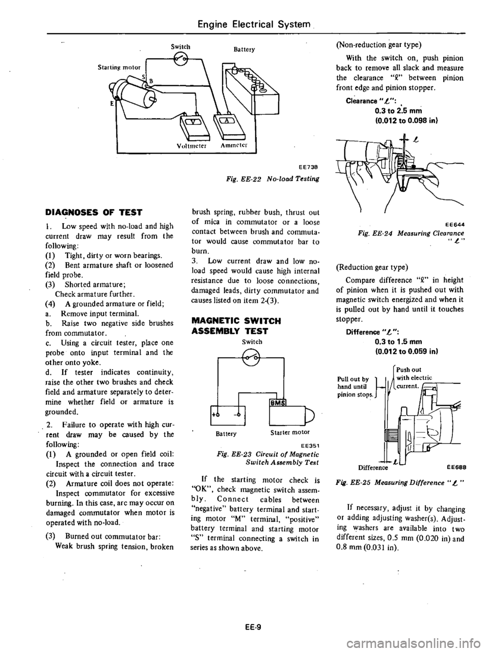
Starting
motor
S
DIAGNOSES
OF
TEST
I
Low
speed
with
no
load
and
high
current
draw
may
result
from
the
following
I
Tight
dirty
or
worn
bearings
2
Bent
armature
shaft
or
loosened
field
probe
3
Shorted
armature
Check
armature
further
4
A
grounded
armature
or
field
a
Remove
input
terminal
b
Raise
two
negative
side
brushes
from
commutator
c
Using
a
circuit
tester
place
one
probe
onto
input
terminal
and
the
other
onto
yoke
d
If
tester
indicates
continuity
raise
the
other
two
brushes
and
check
field
and
armature
separately
to
deter
mine
whether
field
or
armature
is
grounded
2
Failure
to
operate
with
high
cur
rent
draw
may
be
caused
by
the
following
I
A
grounded
or
open
field
coil
Inspect
the
connection
and
trace
circuit
with
a
circuit
tester
2
Armature
coil
does
not
operate
Inspect
commutator
for
excessive
burning
In
this
case
arc
may
occur
on
damaged
commutator
when
motor
is
operated
with
no
load
3
Burned
out
commutator
bar
Weak
brush
spring
tension
broken
Engine
Electrical
System
Switch
Battery
Vultmeter
Ammeter
EE738
Fig
EE
22
No
load
Testing
brush
spring
rubber
bush
thrust
out
of
mica
in
commuta
tor
or
a
loose
contact
between
brush
and
conunuta
tor
would
cause
commutator
bar
to
burn
3
Low
current
draw
and
low
no
load
speed
would
cause
high
internal
resistance
due
to
loose
connections
damaged
leads
dirty
commutator
and
causes
listed
on
item
2
3
MAGNETIC
SWITCH
ASSEMBLY
TEST
Switch
2
1
6
11
p
IB
b
I
Battery
Starter
motor
EE351
Fig
EE
23
Circuit
of
Magnetic
Switch
Assembly
Test
If
the
starting
motor
check
is
OK
check
magnetic
switch
assem
bly
Connect
cables
between
negative
battery
terminal
and
start
ing
motor
M
terminal
positive
battery
terminal
and
starting
motor
8
terminal
connecting
a
switch
in
series
as
shown
above
EE
9
Non
reduction
gear
type
With
the
switch
on
push
pinion
back
to
remove
all
slack
and
measure
the
clearance
between
pinion
front
edge
and
pinion
stopper
Clearance
L
0
3
to
2
5
mm
0
012
to
0
098
in
EE644
Fig
EE
24
Measuring
Clearance
l
Reduction
gear
type
Compare
difference
2
in
height
of
pinion
when
it
is
pushed
out
with
magnetic
switch
energized
and
when
it
is
pulled
out
by
hand
until
it
touches
stopper
Difference
L
0
3
to
1
5
mm
0
012
to
0
059
in
Pull
out
by
hand
until
pinion
stops
Push
out
1
1
n
11
r
L
Difference
EE688
Fig
EE
25
Measuri
g
Difference
L
If
necessary
adjust
it
by
changing
or
adding
adjusting
washer
s
Adjust
ing
washers
are
available
into
two
different
sizes
0
5
mm
0
020
in
and
0
8
mm
0
031
in
Page 168 of 548
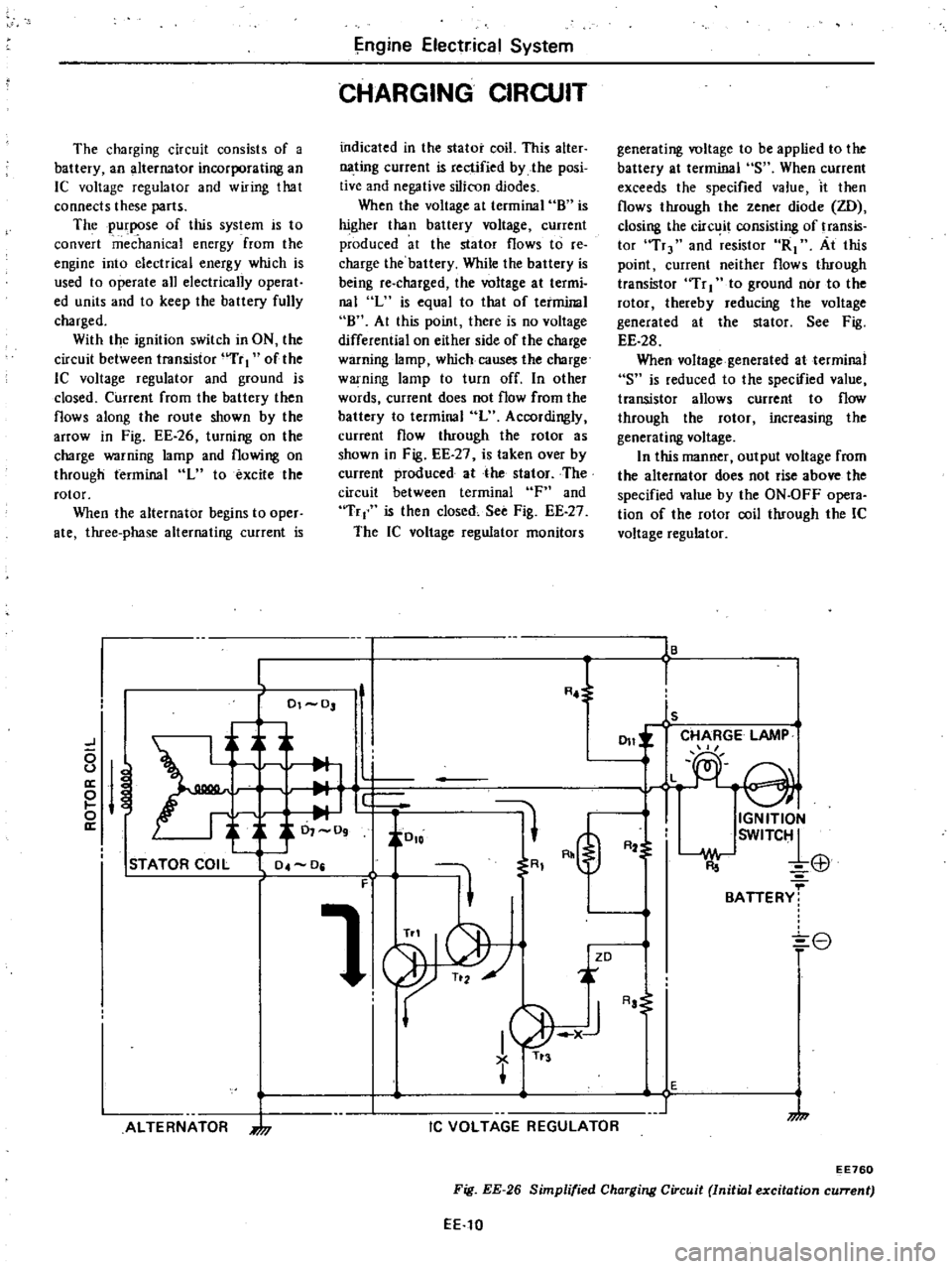
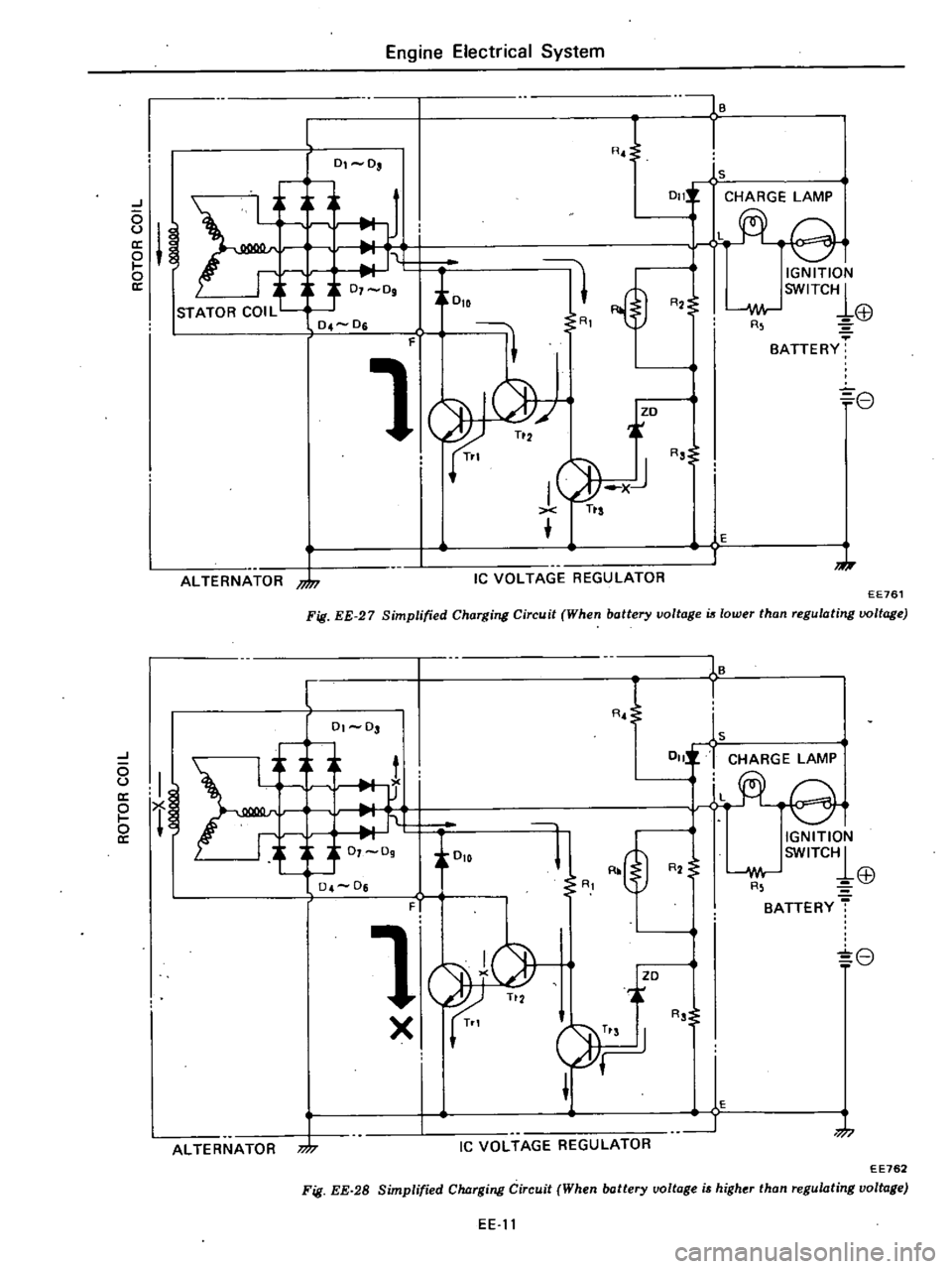
The
charging
circuit
consists
of
a
battery
an
alternator
incorporating
an
IC
voltage
regulator
and
wiring
that
connects
these
parts
The
purpose
of
this
system
is
to
convert
mec
hanka
energy
from
the
engine
into
electrical
energy
which
is
used
to
operate
all
electrically
operat
ed
units
and
to
keep
the
battery
fully
charged
With
the
ignition
switch
in
ON
the
circuit
between
transistor
uTr
I
of
the
lC
voltage
regulator
and
ground
is
closed
Current
from
the
battery
then
flows
along
the
route
shown
by
the
arrOW
in
Fig
EE
26
turning
on
the
charge
warning
lamp
and
flowing
on
through
terminal
L
to
excite
the
rotor
When
the
alternator
begins
to
oper
ate
three
phase
alternating
current
is
ngine
Elect
ical
System
CHARGING
CIRCUIT
indicated
in
the
stator
coil
This
alter
nating
current
is
rectified
by
the
posi
tive
and
negative
silicon
diodes
When
the
voltage
at
terminal
8
is
higher
than
battery
voltage
current
produced
at
the
stator
flows
to
re
charge
the
battery
While
the
battery
is
being
re
charged
the
voltage
at
termi
nal
L
is
equal
to
that
of
terminal
8
At
this
point
there
is
no
voltage
differential
on
either
side
of
the
charge
warning
lamp
which
causes
the
charge
warning
lamp
to
turn
off
In
other
words
current
does
not
flow
from
the
battery
to
terminal
L
Accordingly
current
flow
through
the
rotor
as
shown
in
Fig
EE
27
is
taken
over
by
current
produced
at
the
stator
The
circuit
between
terminal
F
and
Tr
is
then
closed
See
Fig
EE
27
The
IC
voltage
regulator
monitors
generating
voltage
to
be
applied
to
the
battery
at
terminal
S
When
current
exceeds
the
specified
value
it
then
flows
through
the
zener
diode
ZD
closing
the
circ
it
consisting
of
transis
tor
Tr
and
resistor
R1
At
this
point
current
neither
flows
through
transistor
Tr
I
to
ground
nor
to
the
rotor
thereby
reducing
the
voltage
generated
at
the
stator
See
Fig
EE
28
When
voltage
generated
at
terminal
S
is
reduced
to
the
specified
value
transistor
allows
current
to
flow
through
the
rotor
increasing
the
generating
voltage
In
this
manner
output
voltage
from
the
alternator
does
not
rise
above
the
specified
value
by
the
ON
OFF
opera
tion
of
the
rotor
coil
through
the
IC
voltage
regulator
16
L
R
l
I
01
0
ls
CHARGE
LAMP
J
011
L
e
0
u
a
M
e
i
J
0
io
o
IGNITION
a
0
09
SWITC1
R2
El1
STATOR
COIL
04
0
R
F
1
BATTERY
8
ZD
ALTERNATOR
7
I
1
AJ
TI
3
IC
VOLTAGE
REGULATOR
Aa
E
1
7
EE760
Fig
EE
26
Simplified
Charging
Circuit
Initial
excitation
current
EE
10
Page 169 of 548
J
o
u
o
ll
ALTERNATOR
nJn
l
0
0
Engine
Electrical
System
F
00IB
RJ
1
1s
0111
CHARGE
LAMP
rt
ei
tOlD
11
1
IGNITION
SWITC1
R2
i
I
oJor
EB
R
BATTERY
f
3
07
09
0
4
0
1
8
r
I
G
XiJ
Tts
R
o
s
o
E
1
J
IC
VOLTAGE
REGULATOR
Fig
EE
27
Simplified
Charging
Circ14it
When
battery
voltage
is
lower
than
regulating
voltage
EE761
I
h
it
r
f
1
0
0
J
o
U
ll
o
I
o
cr
ALTERNATOR
m
l
01
03
1
X
RJ
16
I
1s
OIlI
r
CHARGE
LAMP
L
l
@
R2
IGNITION
SWITCH1
w
Lp
R
l
Q7
BATTERY
T
8
T
F
i
R
j
JZO
RS
E
J
7
Ie
VOLTAGE
REGULATOR
EE762
Fig
EE
28
Simplified
Cluzrging
Circuit
When
battery
voltage
i
higher
than
regulating
voltage
EE
11