boot DATSUN 210 1979 Service Manual
[x] Cancel search | Manufacturer: DATSUN, Model Year: 1979, Model line: 210, Model: DATSUN 210 1979Pages: 548, PDF Size: 28.66 MB
Page 187 of 548

INSPECTION
I
Disconnect
high
tension
cables
from
spark
plugs
by
pulling
on
boot
not
on
cable
itself
2
Remove
spark
plugs
3
Check
electrodes
and
inner
and
outer
porcelains
of
plugs
noting
the
type
of
deposits
and
the
degree
of
electrode
erosion
Refer
to
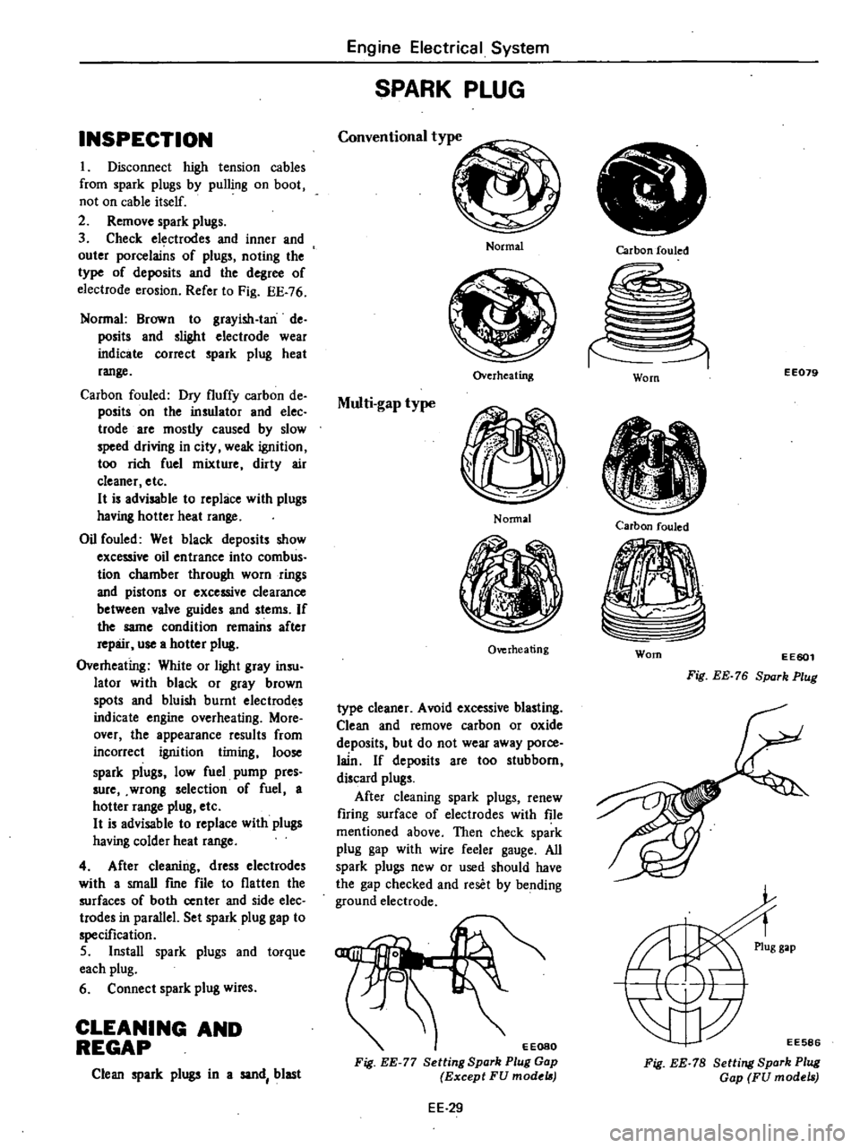
Fig
EE
76
Normal
Brown
to
grayish
Ian
de
posits
and
slighl
electrode
wear
indicate
correct
spark
plug
heat
range
Carbon
fouled
Dry
fluffy
carbon
de
posits
on
the
insulator
and
elec
trode
are
mostly
caused
by
slow
speed
driving
in
city
weak
ignition
too
rich
fuel
mixture
dirty
air
cleaner
etc
H
is
advisable
to
replace
with
plugs
having
hotter
heat
range
Oil
fouled
Wet
black
deposits
show
excessive
oil
entrance
into
comb
us
tion
chamber
through
worn
rings
and
pistons
or
excessive
clearance
between
valve
guides
and
stems
If
the
same
condition
remains
after
repair
use
a
hotter
plug
Overheating
White
or
light
gray
insu
lator
with
black
or
gray
brown
spots
and
bluish
burnt
electrodes
indicate
engine
overheating
More
over
the
appearance
results
from
incorrect
ignition
timing
loose
spark
plugs
low
fuel
pump
pres
sure
wrong
selection
of
fuel
a
hotter
range
plug
etc
H
is
advisable
to
replace
with
plugs
having
colder
heat
range
4
After
cleaning
dress
electrodes
with
a
smaU
fme
file
to
flatten
the
surfaces
of
both
center
and
side
elec
trodes
in
parallel
Set
spark
plug
gap
to
specification
5
Install
spark
plugs
and
torque
each
plug
6
Connect
spark
plug
wires
CLEANING
AND
REGAP
Clean
spark
plugs
in
a
sand
blast
Engine
Electrical
System
SPARK
PLUG
Conventional
type
Normal
Overheating
Multi
gap
type
Nonnal
Overheating
type
cleaner
Avoid
excessive
blasting
Clean
and
remove
carbon
or
oxide
deposits
but
do
not
wear
away
porce
lain
If
deposits
are
too
stubborn
discard
plugs
After
cleaning
spark
plugs
renew
firing
surface
of
electrodes
with
file
mentioned
above
Then
check
spark
plug
gap
with
wire
feeler
gauge
All
spark
plugs
new
or
used
should
have
the
gap
checked
and
reset
by
bending
ground
electrode
EEOSO
Fig
EE
77
Setting
Spark
Plug
Gap
Except
FU
model
EE
29
Carbon
fouled
EE079
Worn
Carbon
fouled
Worn
EE601
Fig
EE
76
Spark
Plug
EE586
Fig
EE
78
Setting
Spark
Plug
Gap
FU
models
Page 219 of 548

I
ht
2nd
fork
r
2
3rd
top
fork
rod
3
Reverse
fork
rod
4
Retaining
pin
5
I
t
2nd
shift
fork
6
3rd
top
shift
fork
7
Checking
ball
plug
8
Check
ban
spring
9
Check
ball
10
Interlock
plunger
11
S
topper
ring
12
Shift
rod
A
bracket
13
Reverse
shift
fork
14
Lock
pin
15
Striking
lever
Manual
Transmission
16
Striking
rod
17
Return
spring
plug
18
Reverse
check
spring
19
Return
pring
20
Plunger
21
D
ring
22
Stopper
pin
bolt
23
Striking
guide
assembly
24
Striking
guide
oil
seal
REMOVAL
To
dismount
transmission
from
the
car
proceed
as
follows
Disconnect
battery
ground
cable
2
Remove
console
box
and
detach
rubber
boots
if
so
equipped
3
Place
transmission
control
lever
in
neutral
position
and
remove
it
m
TM781
Fig
MT
4
Removing
Control
Lever
@
@
25
Control
lever
bushing
26
Expansion
plug
27
Control
pin
bushing
28
Control
arm
pin
29
Control
lever
o
Tightening
torque
kg
m
ft
lb
@
0
5
to
0
8
3
6
tn
5
8
@
1
3
to
1
7
9
to
12
Fig
MT
3
F4W60L
Tra11lmiBSion
Shift
Control
Components
TM094A
4
Jack
up
the
car
and
support
its
weight
on
safety
stands
Use
a
hy
draulic
hoist
or
open
pit
if
available
Make
sure
that
safety
is
insured
5
Disconnect
front
exhaust
tube
and
remove
bolt
securing
exhaust
mounting
bracket
from
exhaust
front
tube
side
6
Disconnect
wires
from
reverse
back
up
lamp
switch
7
Disconnect
speedometer
cable
from
rear
extension
At
the
same
time
removey
top
detecting
switch
if
so
equipped
8
Remove
propeller
shaft
Refer
to
Removal
Section
PO
Note
Plug
up
the
opening
in
the
rear
extension
to
prevent
oil
from
flow
ing
out
MT
3
9
Remove
clutch
operating
cylinder
from
transmission
case
10
Support
engine
by
placing
a
jack
under
oil
pan
with
a
wooden
block
used
between
oil
pan
and
jack
CAUTION
00
not
place
the
jack
under
the
oil
pan
drain
plug
11
Support
transmission
with
a
transmission
jack
12
Loosen
rear
engine
mount
se
curing
bolts
CD
temporarily
and
re
move
crossmember
mounting
bolts
V
Page 233 of 548

Manual
Transmission
S
R
o
o
D
l
@
@
l
@
l
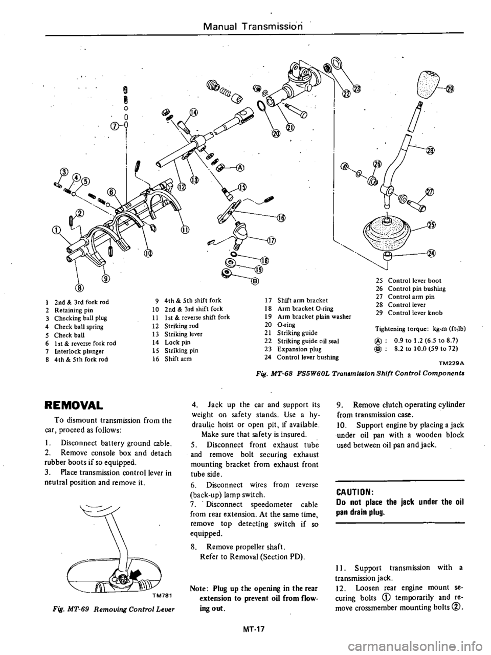
25
Control
lever
boot
26
Control
pin
bushing
27
Control
arm
pin
28
Control
lever
29
Control
lever
knob
1
2nd
3rd
fork
rod
9
4th
5th
shift
fork
17
Shift
arm
bracket
2
Retaining
pin
10
2nd
3rd
shift
fork
18
Arm
bracket
O
ring
3
Checking
ball
plug
11
Ist
reverse
shift
fork
19
Arm
bracket
plain
washer
4
Check
ball
spring
12
Striking
rod
20
O
ring
5
Check
ball
13
Striking
lever
21
S
lriking
guide
6
ht
reverse
fork
rod
14
Lock
pin
22
Striking
guide
oil
seal
7
Interlock
plunger
15
Striking
pin
23
Expansion
plug
8
4th
5th
fork
rod
16
Shift
arm
24
Control
lever
bushing
Tightening
torque
kg
m
fHb
@
0
9
to
1
2
6
5
to
8
7
@
8
2
to
to
O
59
to
72
TM229A
Fig
MT
68
FS5W60L
Transmission
Shift
Control
Components
REMOVAL
4
Jack
up
the
car
and
supporl
its
weight
on
safety
slands
Use
a
hy
draul
c
hoist
or
open
pit
if
available
Make
sure
that
safety
is
insured
S
Disconnect
front
exhaust
tube
and
remove
bolt
securing
exhaust
mounting
bracket
from
exhaust
front
tube
side
6
Disconnect
wires
from
reverse
back
up
lamp
switch
7
Disconnect
speedometer
cable
from
rear
extension
At
the
same
time
remove
top
detecting
switch
if
so
equipped
8
Remove
propeller
shaft
Refer
to
Removal
Section
PD
To
dismount
transmission
from
the
car
proceed
as
follows
Disconnect
battery
ground
cable
2
Remove
console
box
and
detach
rubber
boots
if
so
equipped
3
Place
transmission
control
lever
in
neutral
position
and
remove
it
CJi
J
TM781
Note
Plug
up
the
opening
in
the
rear
extension
to
prevent
oil
from
flow
ing
out
Fig
MT
69
Removing
Control
Lever
MT
17
9
Remove
clutch
operating
cylinder
from
transmission
case
10
Support
engine
by
placing
a
jack
under
oil
pan
with
a
wooden
block
used
between
oil
pan
and
jack
CAUTION
Do
not
place
the
jack
under
the
oil
pan
drain
plug
II
Support
transmission
with
a
transmission
jack
12
Loosen
rear
engine
mount
se
curing
bolts
CD
temporarily
and
re
move
crossmember
mounting
bolts
CV
Page 358 of 548

If
leakage
oCcurs
at
end
around
joints
re
tighten
Of
if
necessary
re
place
faulty
parts
INSTALLATION
Pay
particular
attention
to
follow
ing
instructions
when
installing
brake
lines
I
Leave
a
sulfident
space
between
brake
lines
and
adjacent
parts
so
that
brake
lines
are
completely
free
from
vibration
during
driving
2
Be
careful
not
to
warp
or
twist
brake
lines
3
When
installing
brake
tube
keep
a
certain
distance
between
tube
and
adjacent
parts
as
follows
Tube
to
rotating
parts
30
mm
1
18
in
Tube
to
moving
parts
10
mm
10
39
in
Tube
to
other
palls
5
mm
10
20
in
4
Always
fasten
brake
tubes
with
mounting
clips
where
necessary
On
rear
axle
case
are
two
double
dips
which
should
be
used
to
secure
brake
tubes
in
manner
described
be
low
Bend
short
clip
straight
up
With
brake
tube
on
long
clip
bend
clip
up
and
around
tube
Finally
wrap
short
clip
around
tube
to
secure
the
in
slallation
f
J
i
2
BA141
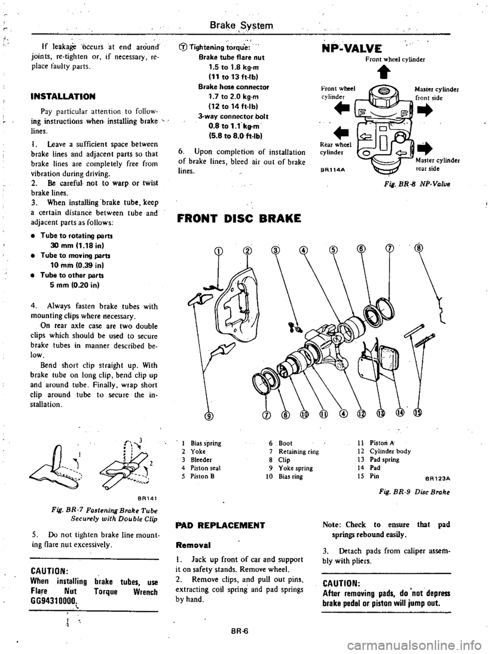
Fig
BR
7
Fastening
Brake
Tube
Securely
with
Double
Clip
5
Do
not
tighten
brake
line
mount
ing
flare
nut
excessively
CAUTION
When
installing
Fla
e
Nut
6694310000
brake
tubes
use
Torque
Wrench
Brake
System
t
D
Tightening
torque
Brake
tube
flare
nut
1
5
to
1
8
kg
m
11
to
13
ft
lb
Brake
hose
connector
1
7
to
2
0
kg
m
112
to
14
ft
lb
J
way
connector
bolt
0
8
to
1
1
kltm
5
8
to
8
0
ft
Ib
NP
VALVE
Front
wheel
cylinder
Front
wheel
cylinder
Master
cylinder
front
jde
6
Upon
completion
of
installation
of
brake
lines
bleed
air
out
of
brake
lines
Rear
wheel
cylinder
BR114A
Master
cylinder
rear
side
Fig
BR
B
NP
Valve
FRONT
DISC
BRAKE
9
ilJ
I
Bias
s
pring
2
Yoke
3
Bleeder
4
Piston
seal
5
Piston
B
11
Piston
A
12
Cylinder
body
13
Pad
spring
14
Pad
15
Pin
6
Boot
7
Retaining
ring
8
Clip
9
Yoke
spring
10
Bias
ring
BR123A
Fig
BR
9
Di
c
Broke
PAD
REPLACEMENT
Note
Check
to
ensure
that
pad
springs
rebound
easily
3
Detach
pads
from
caliper
assem
bly
with
pliers
Removal
I
Jack
up
front
of
car
and
support
it
on
safety
stands
Remove
wheel
2
Remove
clips
and
pull
out
pins
extracting
coil
spring
and
pad
springs
by
hand
CAUTION
After
removing
pads
do
not
depress
brake
pedal
or
piston
will
jump
out
BR
Page 361 of 548

BR563
Fig
BR
10
Removing
Pad
Inspection
Clean
pads
with
cleaning
solvent
CAUTION
Use
brake
fluid
to
clean
Never
use
mineral
oil
2
When
pads
are
heavily
fouled
with
oil
or
grease
or
when
pad
is
deteriorated
or
deformed
replace
it
3
If
pad
is
worn
to
less
than
the
specified
value
replace
Pad
wear
limit
Minimum
thickness
t
6
mm
0
063
in
Note
Always
replace
pads
in
pad
kit
four
pads
two
clips
four
pad
pins
and
four
pad
springs
4
Check
rotor
referring
to
Rotor
for
inspection
Installetlon
I
Clean
and
apply
P
RC
grease
on
yoke
guide
groove
of
cylinder
body
sliding
contact
portions
of
yoke
and
end
surface
of
piston
Note
a
Do
not
use
common
brake
grease
b
Be
careful
not
to
get
brake
grease
on
rotor
and
pads
2
Loosen
air
bleeder
and
push
pis
ton
B
outer
piston
in
cylinder
until
end
surface
of
piston
B
coincides
with
end
surface
of
retaining
ring
on
boot
Then
inner
pad
can
be
installed
Brake
System
BR564
Fig
BR
11
Pushing
Piston
CAUTION
Piston
can
be
easily
pushed
in
by
hand
but
if
pushed
too
far
groove
of
piston
will
go
inside
of
piston
seal
as
shown
in
Fig
BR
12
At
this
point
if
piston
is
pressured
or
moved
piston
seal
will
be
damaged
If
piston
has
been
pushed
in
too
far
remove
brake
assembly
and
disassemble
it
Then
push
piston
out
in
the
direction
shown
by
arrow
Assemble
it
again
referring
to
follow
ing
section
00
I
Normal
I
position
L
BR409
Fig
BR
12
Position
for
Pushing
Piston
3
Push
piston
A
inner
piston
in
cylinder
by
pulling
yoke
as
shown
The
outer
pad
can
then
be
installed
BRS6S
Fig
BR
13
Pulling
in
Piston
A
BR
7
4
After
installing
pads
depress
brake
pedal
several
times
and
pads
will
settle
into
proper
position
Note
When
worn
out
pads
are
re
placed
with
new
ones
brake
fluid
may
overflow
reservoir
While
re
placing
pads
keep
loosening
bleeder
to
release
brake
fluid
5
Install
wheels
and
lower
car
to
ground
REMOVAL
I
Remove
pads
Refer
to
Pad
Re
placement
2
Remove
brake
tube
from
caliper
assembly
CAUTION
When
removing
brake
tube
use
suit
able
tube
wrench
Never
use
open
end
or
adjustable
wrench
Note
Plug
up
hole
in
caliper
so
that
brake
fluid
does
not
flow
out
from
cylinder
body
3
Loosen
bolts
securing
cylinder
body
to
knuckle
spindle
and
remove
caliper
assembly
from
strut
DISASSEMBLY
I
Drain
brake
fluid
from
top
hole
of
cylinder
body
2
Push
both
pistons
A
and
B
into
cylinder
Refer
to
Pad
Replacement
3
Tap
cylinder
body
lightly
with
a
plastic
hammer
Cylinder
will
then
separate
from
yoke
BR115A
Fig
BR
14
Tapping
Cylinder
Block
Page 362 of 548

Remove
bias
ring
from
piston
A
S
Remove
retaining
rings
and
boots
at
the
end
of
both
pistons
A
and
B
I
Biuring
2
Boot
3
Retaining
ring
BA567
Fig
BR
15
Cylinder
Body
and
Pi
tan
6
Force
out
pistons
from
cylinder
by
feeding
compressed
air
gradually
WARNING
Gradually
increase
air
pressurs
10
that
piston
does
not
pop
out
7
Remove
piston
seals
CAUTION
Be
careful
not
to
damBlle
piston
and
cylinder
boily
8
Remove
yoke
spring
from
yoke
INSPECTION
Clean
au
parts
and
check
u
fol
lows
CAutiON
Use
brake
fluid
to
claan
Never
use
minersl
oil
Cylinder
bod
1
Check
inside
surface
of
cylinder
for
score
rust
wear
damage
or
pres
ence
of
foreign
substances
If
any
surface
fault
is
detected
replace
cyl
inder
body
2
Minor
damage
from
rust
of
foreign
substances
may
be
eliminated
by
polishing
surface
with
a
fme
emery
cloth
If
damage
is
major
cylinder
assembly
must
be
replaced
Brake
System
Yoke
Check
for
wear
cracks
or
other
damage
Replace
if
any
fault
is
de
tected
PIston
Check
piston
for
score
rust
wear
damage
orpresenco
of
foreign
sub
stances
Replace
if
any
fault
is
de
tected
CAUTION
Piston
sliding
surface
is
plated
00
not
polish
with
emery
peper
even
if
rust
or
foreign
matter
is
sticked
on
sliding
surface
PIston
seal
end
dust
seel
Replace
piston
seal
and
dust
seal
at
each
dis
mbly
ASSEMBLY
1
Apply
rubber
grease
to
cylinder
bore
and
install
piston
seal
2
Insert
bias
ring
into
piston
A
so
that
the
roundish
portion
of
it
faces
the
bottom
of
piston
A
bore
I
ID
J
if
C
jt
11
e
1
@
I
j
BA
I
Roundish
portion
3
Chamfer
2
Piston
A
4
Yoke
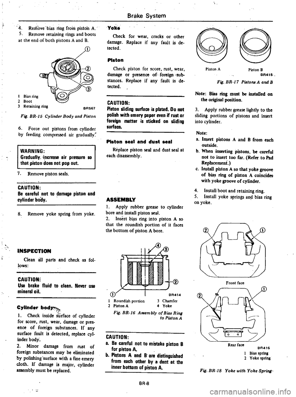
Fig
BR
16
A
embly
af
Bia
Ring
to
Piston
A
CAUTION
a
Be
careful
not
to
mistaka
piston
B
for
piston
A
b
Pistons
A
and
B
are
distinguished
from
each
other
by
a
dent
at
the
inner
bottom
of
piston
A
BR
8
Piston
A
Piston
B
BR41S
Fig
BR
17
Pisto
A
and
B
Note
Bias
ring
must
be
instaDed
on
the
original
position
3
Apply
rubber
grease
lightly
to
the
sliding
portions
of
pistons
and
insert
into
cylinder
Note
a
Insert
pistons
A
and
B
from
each
outside
b
When
inserting
pistons
be
careful
not
to
insert
too
far
Refer
to
Pad
Replacemeni
c
Install
piston
A
so
that
yoke
groove
of
bias
ring
of
piston
A
coincides
with
yoke
groove
of
cylinder
4
Instau
boot
and
retaining
ring
S
Install
yoke
springs
an
bias
ring
on
yoke
Front
face
1
1
0
Rear
face
BA416
1
Bias
Sprinl
2
Yoke
spring
Fig
BR
18
Yoke
with
Yoke
Spring