high DATSUN 210 1979 Owner's Manual
[x] Cancel search | Manufacturer: DATSUN, Model Year: 1979, Model line: 210, Model: DATSUN 210 1979Pages: 548, PDF Size: 28.66 MB
Page 95 of 548
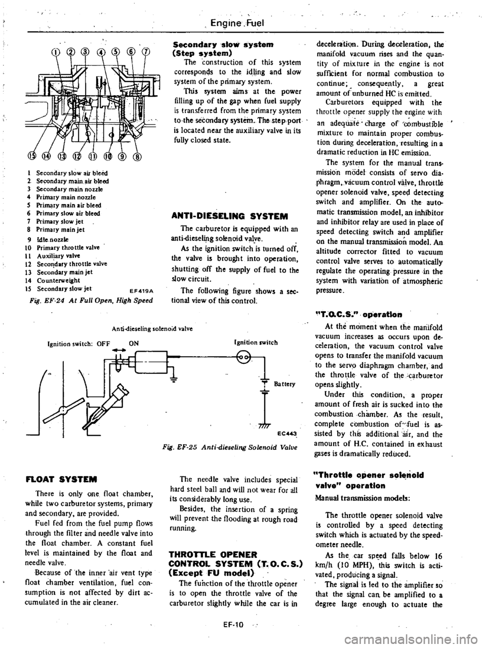
I
Secondary
slow
air
bleed
2
Secondary
main
air
bleed
3
Secondary
main
nozzle
4
Primary
main
nozzle
5
Primary
main
air
bleed
6
Primary
slow
air
bleed
7
Primary
slow
jet
8
Primary
main
jet
9
Idle
nozzle
10
Primary
throttle
valve
II
Auxiliary
valve
12
Seco
dary
throttle
valve
13
Secondary
main
jet
14
Counterweight
IS
Secondary
slow
jet
EF419A
Fig
EF
24
At
Full
Open
High
Speed
Engine
Fuel
Secondary
slow
system
Step
system
The
construction
of
this
system
corresponds
to
the
idling
and
slow
system
of
the
primary
system
This
system
aims
at
the
power
filling
up
of
the
gap
when
fuel
supply
is
transferred
from
the
primary
system
to
the
secondary
system
The
stepport
is
located
near
the
auxiliary
valve
in
its
fully
closed
state
ANTI
DIESELING
SYSTEM
The
carburetor
is
equipped
with
an
anti
liese1i
lg
solenoid
valye
As
the
ignition
switch
is
turned
off
the
valve
is
brought
into
operation
shutting
off
the
supply
of
fuel
to
the
slow
circuit
The
following
figure
shows
a
see
tional
view
of
this
control
An
ti
dies
eling
solenoid
valve
Ignition
switch
OFF
ON
t
L
li
FLOAT
SYSTEM
There
is
only
one
float
chamber
while
two
carburetor
systems
primary
and
secondary
are
provided
Fuel
fed
from
the
fuel
pump
flows
through
the
filter
and
needle
valve
into
the
float
chamber
A
constant
fuel
level
is
maintained
by
the
float
and
needle
valve
Because
of
the
inner
air
vent
type
float
chamber
ventilation
fuel
con
sumption
is
not
affected
by
dirt
ac
cumulated
in
the
air
cleaner
Ignition
switch
Q
1
T
Battery
niT
EC
3
Fig
EF
25
Anti
dieseling
Solenoid
Valve
The
needle
valve
includes
special
hard
steel
ball
and
wiD
not
wear
for
all
its
considerably
long
use
Besides
the
insertion
of
a
spring
will
prevent
the
flooding
at
rough
road
running
THROTTLE
OPENER
CONTROL
SYSTEM
T
O
C
S
Except
FU
model
The
function
of
the
throttle
opener
is
to
open
the
throttle
valve
of
the
carburetor
slightly
while
the
car
is
in
EF
10
deceleration
During
deceleration
the
manifold
vacuum
rises
and
the
quan
tity
of
mixture
in
the
engine
is
not
suffICient
for
normal
combustion
to
continue
4
consequently
a
great
amount
of
unburned
HC
is
emitted
Carburetors
equipped
with
the
throttle
opener
supply
the
engine
with
an
adequate
charge
of
combustible
mixture
to
maintain
proper
combus
tion
during
deceleration
resulting
in
a
dramatic
reduction
in
HC
emission
The
system
for
the
manual
trans
mission
model
consists
of
servo
dia
phragm
vlicuum
control
valve
throttle
opener
solenoid
valve
spee
l
detecting
switch
and
amplifier
On
the
auto
matic
transmission
model
an
inhibitor
and
inhibitor
relay
are
used
in
place
of
speed
detecting
switch
and
amplifier
on
the
manual
transmission
model
An
altitude
corrector
fitted
to
vacuum
control
valve
serves
to
automatically
regulate
the
operating
pressure
in
the
system
with
variation
of
atmospheric
pressure
T
o
C
S
n
operatIon
At
the
moment
when
the
manifold
vacuum
increases
as
occurs
upon
de
celeration
the
vacuum
control
valve
opens
to
transfer
the
manifold
vacuum
to
the
servo
diaphragm
chamber
and
the
throttle
valve
of
the
carburetor
opens
slightly
Under
this
condition
a
proper
amount
of
fresh
air
is
sucked
into
the
combustion
chamber
As
the
result
complete
combustion
of
fuel
is
as
sisted
by
this
additional
air
and
the
amount
of
H
C
contained
in
exhaust
gases
is
dramatically
reduced
Throttle
Clpener
sol
nold
valve
operation
Manual
transmission
models
The
throttle
opener
solenoid
valve
is
controlled
by
a
speed
detecting
switch
which
is
actuated
by
the
speed
ometer
needle
As
the
car
sp
ed
falls
below
16
km
h
10
MPH
this
switch
is
acti
vated
producing
a
signal
The
signal
is
led
to
the
amplifier
so
that
the
signal
can
be
amplified
to
a
degree
large
enough
to
actuate
the
Page 97 of 548
Fuel
shut
oH
s
stein
operation
During
deceleration
when
the
en
gine
speed
is
above
a
certain
level
the
anti
dieseling
solenoid
valve
of
the
carburetor
closes
so
that
the
fuel
is
shut
off
When
engine
speed
falls
below
a
certain
level
the
anti
dieseling
solenoid
vaJv
oP
lS
so
that
the
f
el
flows
However
if
the
engine
speed
is
below
the
designated
level
even
during
deceleration
the
fuel
shut
off
system
does
not
operate
When
the
shift
lever
is
in
neutral
the
fuel
shut
off
system
does
not
operate
The
functions
of
each
part
of
this
system
are
as
follows
I
Engine
revolution
switch
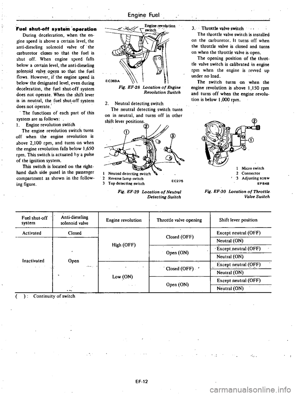
The
engine
revolution
switch
turns
off
when
the
engine
revolution
is
above
2
100
rpm
and
turns
on
when
the
engine
revolution
falls
below
1
650
rpm
This
switch
is
actuated
hy
a
pulse
of
the
ignition
system
This
switch
is
located
on
the
right
hand
dash
side
panel
in
the
passenger
compartment
as
shown
in
the
follow
ing
figure
Engine
Fuel
I
Fig
EF
28
Location
of
Engine
Revolution
Switch
2
Neutral
detecting
switch
The
neutral
detecting
switch
turns
on
in
neutral
and
turns
off
in
other
shift
lever
positions
h
1
Neutral
detecting
switch
2
Revenelamp
switch
3
Top
detectim
switch
EC275
3
Throttle
valve
switch
The
throttle
valve
switch
is
installed
on
the
carburetor
It
turns
off
when
the
throttle
valve
is
closed
and
turns
on
when
the
throttle
valve
is
open
The
opening
position
of
the
throt
tle
valve
switch
is
calibrated
in
engine
rpm
when
the
engine
is
revved
up
under
no
load
The
switch
turns
on
when
the
engine
revolution
is
above
1
150
rpm
and
turns
off
when
the
engine
revolu
tion
is
below
1
000
rpm
1
Micro
switch
2
Connector
3
Adjusting
screw
EF848
Fig
EF
30
Location
of
Throttle
Valve
Switch
Fuel
shut
off
Anti
dieseling
Engine
revolution
Throttle
valve
opening
Shift
lever
position
system
solenoid
valve
Activated
Closed
Except
neutral
OFF
Closed
OFF
Neutral
ON
High
OFF
Except
neutral
OFF
Open
ON
Inactivated
Open
Neutral
ON
Closed
OFF
Excep
t
neutral
O
F
Low
ON
Neutral
ON
Except
neutral
OFF
Open
ON
Neutral
ON
Continuity
of
switch
Fig
EF
29
Locotion
of
Neutral
Detecting
Switch
EF
12
Page 98 of 548
ELECTRIC
AUTOMATIC
CHOKE
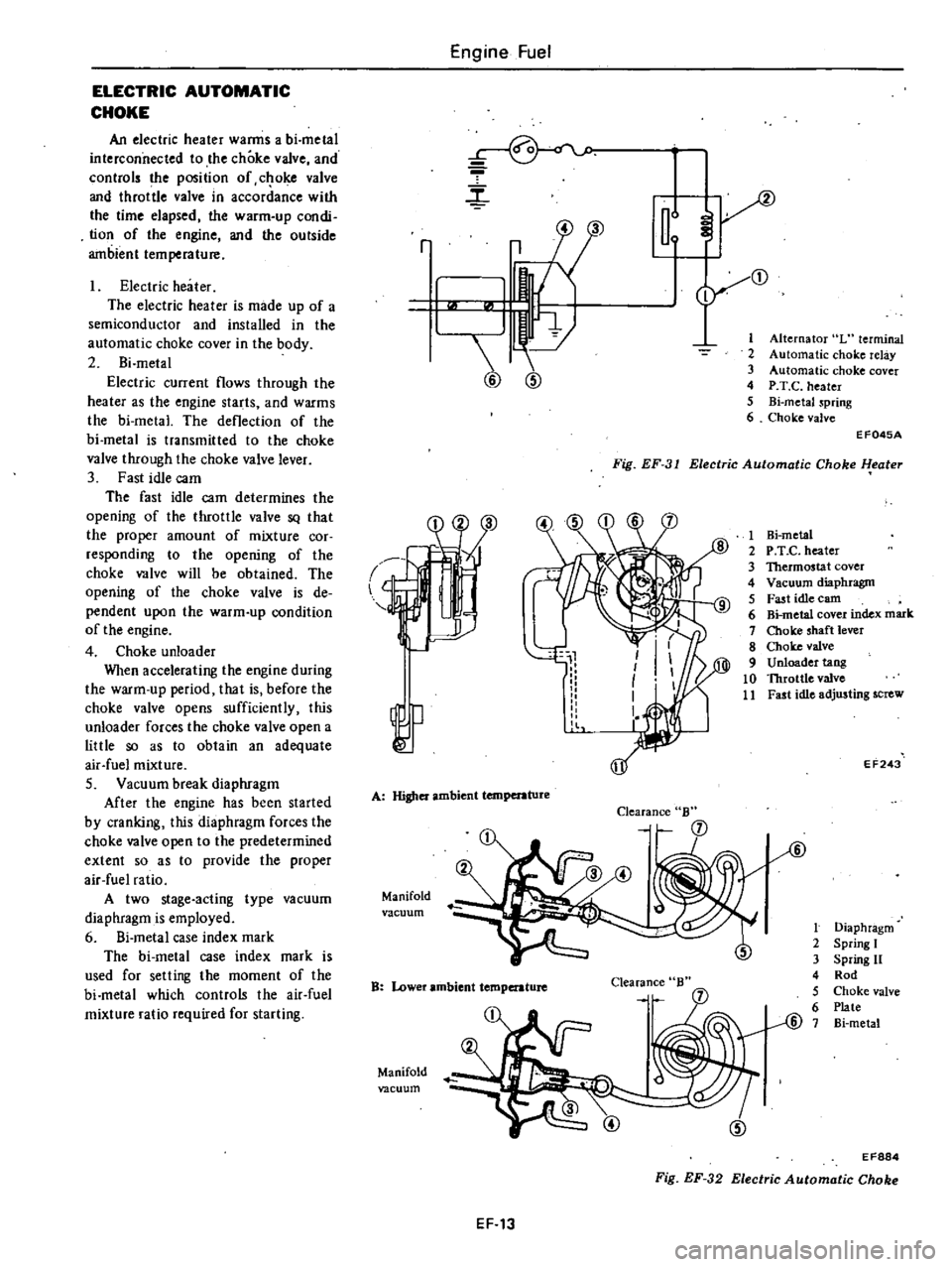
An
electric
heater
warms
a
bi
metal
interconnected
to
the
choke
valve
and
controls
the
position
of
c
oke
valve
and
throttle
valve
in
accordance
with
the
time
elapsed
the
warm
up
condi
tion
of
the
engine
and
the
outside
ambient
temperature
Electric
heater
The
electric
heater
is
made
up
of
a
semiconductor
and
installed
in
the
automatic
choke
cover
in
the
body
2
Bi
metal
Electric
current
flows
through
the
heater
as
the
engine
starts
and
warms
the
bi
metal
The
deflection
of
the
bi
metal
is
transmitted
to
the
choke
valve
through
the
choke
valve
lever
3
Fast
idle
cam
The
fast
idle
cam
determines
the
opening
of
the
throttle
valve
SQ
that
the
proper
amount
of
mixture
cor
responding
to
the
opening
of
the
choke
valve
will
be
obtained
The
opening
of
the
choke
valve
is
de
pendent
upon
the
warm
up
condition
of
the
engine
4
Choke
unloader
When
accelerating
the
engine
during
the
warm
up
period
that
is
before
the
choke
valve
opens
sufficiently
this
unloader
forces
the
choke
valve
open
a
little
so
as
to
obtain
an
adequate
air
fuel
mixture
S
Vacuum
break
diaphragm
After
the
engine
has
been
started
by
cranking
this
diaphragm
forces
the
choke
valve
open
to
the
predetermined
extent
so
as
to
provide
the
proper
air
fuel
ratio
A
two
stage
acting
type
vacuum
diaphragm
is
employed
6
Si
metal
case
index
mark
The
bi
metal
case
index
mark
is
used
for
selling
the
moment
of
the
bi
metal
which
controls
the
air
fuel
mixture
ratio
required
for
starting
Engine
Fuel
r
m
2
3
4
5
6
r
3
1
@
@
Alternator
L
terminal
Automatic
choke
relay
Automatic
choke
cover
P
T
C
heater
Bi
metaJ
spring
Choke
valve
Fig
EF
31
Electric
Automatic
Choke
l
eater
EF045A
l
A
Higher
ambient
temperature
Manifold
vacuum
Clearance
B
B
Lower
ambient
temperature
Clearance
Manifold
vacuum
1
Hi
metal
2
P
T
e
heater
3
Thermostat
cover
4
Vacuum
diaphragm
5
Fast
idle
earn
6
Bi
metal
cover
index
mark
7
Choke
shaft
lever
8
Choke
valve
9
Unloader
tang
10
Throttle
valve
11
Fast
idle
adjusting
screw
EF243
t
Diaphragm
2
Spring
I
3
Spring
11
4
Rod
5
Choke
valve
6
Plate
@
7
Bi
metal
EF884
Fig
EF
32
Electric
Automatic
Choke
EF
13
Page 104 of 548
1
Ignition
switch
2
Amplifier
3
Speed
switch
Note
a
Tightening
torque
is
1
8
to
2
2
kg
m
13
to
16
ft
Ib
b
After
replacement
start
engine
and
check
to
be
sure
that
fuel
is
not
leaking
and
that
anti
dieseling
sole
noid
i
in
good
condition
EFOSOA
Fig
EF47
Checking
Anti
dieaeling
Solenoid
l
SJ
Engine
Fuel
THROTTLE
OPENER
CONTROL
SYSTEM
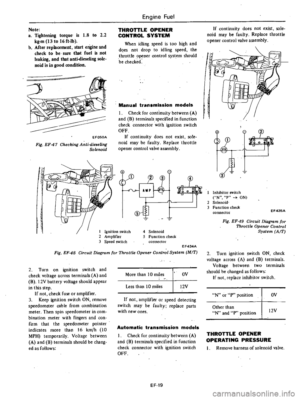
When
idling
speed
is
too
high
and
does
not
drop
to
idling
speed
the
throttle
opener
control
system
should
be
checked
Manual
transmission
models
I
Check
for
continuity
between
A
and
8
terminals
specified
in
function
check
connector
with
ignition
switch
OFF
If
continuity
does
not
exist
sole
noid
may
be
faulty
Replace
throttle
opener
control
valve
assembly
e
1J
3
o
0
5
4
Solenoid
5
F
nction
check
connector
EF434A
Fig
EF
48
Circuit
Diagram
for
Throttle
Opener
Control
System
MIT
2
Turn
on
ignition
switch
and
check
voltage
across
terminals
A
and
8
l2V
battery
voltage
should
appear
in
this
step
If
not
check
fuse
or
amplifier
3
Keep
ignition
switch
ON
remove
speedometer
cable
from
combination
meter
Then
spin
speedometer
in
com
bination
meter
with
fingers
and
con
firm
that
the
speedometer
pointer
indicates
more
than
16
km
h
10
MPH
temporarily
Voltage
between
A
and
8
terminals
should
be
chang
ed
as
follows
More
than
10
miles
OV
Less
than
10
miles
12V
If
not
amplifier
or
speed
detecting
switch
may
be
faulty
replace
parts
with
new
ones
Automatic
transmission
models
I
Check
for
continuity
between
A
and
8
terminals
specified
in
function
check
connector
with
ignition
switch
OFF
EF
19
If
continuity
does
not
exist
sole
noid
may
be
faulty
Replace
throttle
opener
control
valve
assembly
If
t
r
If
I
Inhibitor
switch
N
p
ON
2
Solenoid
3
Function
check
connector
EF43SA
Fig
EF
49
Circuit
Diagram
for
Throttle
Opener
Control
System
AfT
2
Turn
ignition
switch
ON
check
voltage
across
A
and
8
terminals
Voltage
between
two
terminals
should
be
changed
as
follows
If
not
replace
inhibitor
switch
N
or
p
position
OV
Other
than
N
and
p
position
l2V
THROTTLE
OPENER
OPERATING
PRESSURE
I
Remove
harness
of
solenoid
valve
Page 105 of 548
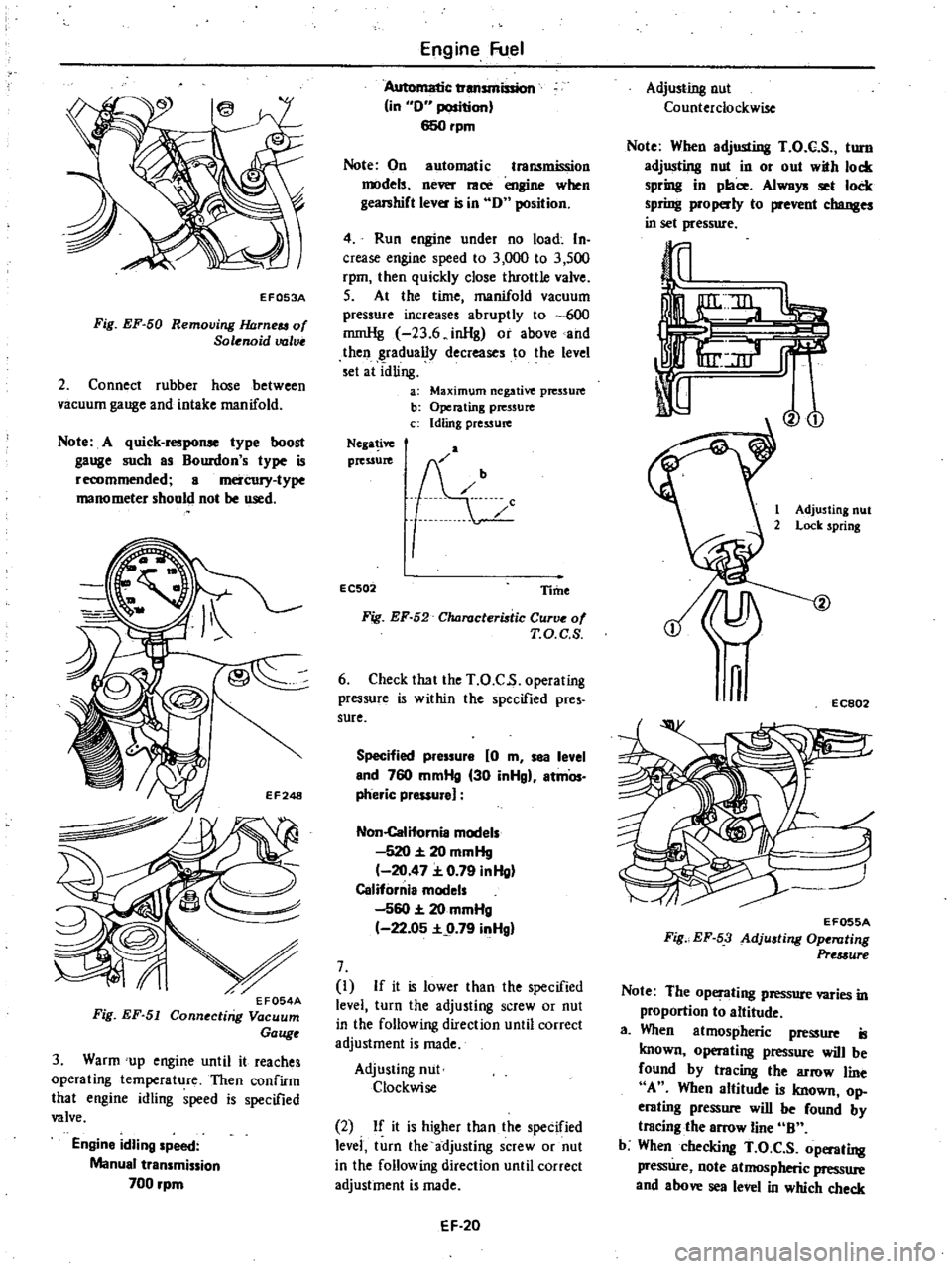
EF053A
Fig
EF
50
Removing
JWrneu
of
Solenoid
valve
2
Connect
rubber
hose
between
vacuum
gauge
and
intake
manifold
Note
A
quick
response
type
boost
gauge
such
as
Bourdon
s
type
is
recommended
a
mercury
type
manometer
should
not
be
used
3
Warm
up
engine
until
it
reaches
operating
temperature
Then
confirm
that
engine
idling
speed
is
specified
valve
Engine
idling
speed
Manual
transmission
700
rpm
Engine
Fuel
Automatic
transmission
in
0
position
650rpm
Note
On
automatic
transmission
models
never
race
engine
when
gearshift
lever
is
in
0
position
4
Run
engine
under
no
load
In
crease
engine
speed
to
3
000
to
3
500
rpm
then
quickly
close
throttle
valve
S
At
the
time
manifold
vacuum
pressure
increases
abruptly
to
600
rnmHg
23
6
inHg
or
above
and
then
gradually
decreases
to
the
level
set
at
idling
a
Maximum
negative
pressure
b
Operating
pressure
c
Idling
pressure
Nega
ive
pressure
EC502
Time
Fig
EF
52
Characteristic
Curve
of
T
O
C
S
6
Check
that
the
T
O
C
s
operating
pressure
is
within
the
specified
pres
sure
Specified
pressure
0
m
sea
level
end
760
mmHg
30
inHgl
atmOs
pheric
pressure
Non
Califomia
models
520
20
mmHg
20
47
0
79
inHg
California
models
560
20
mmHg
22
05
9
79
inHgl
7
I
If
it
is
lower
than
the
specified
level
turn
the
adjusting
screw
or
nut
in
the
following
direction
until
correct
adjustment
is
made
Adjusting
nut
Clockwise
2
If
it
is
higher
than
the
specified
levei
turn
the
adjusting
screw
or
nut
in
the
following
direction
until
correct
adjustment
is
made
EF
20
Adjusting
nut
Counterclockwise
Note
When
adjusting
T
O
C
S
turn
adjusting
nut
in
or
out
with
lock
spring
in
place
Always
set
lock
spring
properly
to
prevent
changes
in
set
pressure
Vo
1
Adjusting
nut
2
Lock
spring
n
EC802
EF055A
Fig
EF
53
Adjusting
Ope
llting
Pre
3ure
Note
The
operating
pressure
varies
in
proportion
to
altitude
a
When
atmospheric
pressure
is
known
operating
pressure
will
be
found
by
tracing
the
arrow
line
A
When
altitude
is
known
op
erating
pressure
will
be
found
by
tracing
the
arrow
line
B
b
When
checking
T
O
C
S
operating
pressure
note
atmospheric
pressure
and
above
sea
level
in
which
check
Page 106 of 548

is
to
be
made
and
determine
set
pressure
by
the
information
fur
nished
For
example
if
above
sea
level
is
1
000
m
3
280
ft
operating
pres
sure
will
then
be
475
mmHg
18
7
inHg
on
non
California
models
or
495
mmHg
19
5
inHg
on
California
models
In
other
words
T
O
C
S
operates
at
475
mmHg
18
7
inHg
or
490
mmHg
19
3
inHg
8
Race
engine
and
check
for
adjust
ment
9
If
engine
speed
will
not
drop
to
idling
speed
when
checking
throttle
opener
operating
pressure
proceed
as
follows
I
Turn
adjusting
screw
counter
clockwise
so
that
throttle
opener
oper
ating
pressure
is
on
high
vacuum
side
Engine
Fuel
25
mmHg
0
98
inHg
away
from
the
specified
value
2
Turn
adjusting
screw
l
O
of
a
turn
clockwise
so
that
throttle
opener
oper
ating
pressure
drops
by
25
mmHg
0
98
inHg
10
If
throttle
opener
operating
pressure
cannot
be
observed
clearly
even
in
step
9
proceed
as
follows
I
Turn
adjusting
screw
counter
clockwise
so
that
tluottle
opener
oper
ating
pressure
is
on
high
vacuum
side
50
mmHg
1
97
inHg
away
from
mid
point
of
the
specified
range
2
Turn
adjusting
screw
l
of
a
turn
clockwise
Note
The
throttle
opener
operating
pressure
should
be
correctly
set
within
the
specified
range
after
the
above
adju
stments
even
if
the
en
gine
speed
cannot
be
decreased
to
idling
inHg
mmHg
30
750
29
28
24
A
600
700
23
27
560
26
22
550
650
21
25
0
0
20
24
500
600
0
0
19
23
c
o
c
22
ii
18
0
0
450
550
E
c
0
17
2
16
20
400
500
15
B
Non
California
model
350
14
California
model
13
300
5
000
6
000
1ft
0
1
000
2
000
3
001
4
000
0
0
5
1
5
2
km
Altitude
EF056A
Fig
EF
54
Clumges
in
Operating
Pressure
Versus
Changes
in
Atmospheric
Pressure
EF
21
SERVO
DIAPHRAGM
STROKE
I
Connect
engine
tachometer
2
Warm
up
engine
until
it
reaches
operating
temperature
3
Disconnect
rubber
hose
between
servo
diaphragm
and
vacuum
control
valve
Then
connect
rubber
hose
to
in
take
manifold
Servo
diaphragm
Rubber
hose
T
O
C
S
solenoid
valve
T
O
C
S
control
valve
EF250
EF057A
Fig
EF
55
Connecting
Rubber
Hose
to
Intake
Manifold
4
Servo
diaphragm
is
functioning
properly
if
engine
speed
comes
into
the
specified
range
Specified
engine
speed
1
650
to
1
850
rpm
except
Californial
1
900
to
2
100
rpm
for
California
5
If
necessary
adjust
engine
speed
until
it
is
in
the
specified
range
using
servo
diaphragm
adjusting
screw
When
engine
speed
is
lower
than
the
prescribed
range
Turn
adjusting
screw
clockwise
When
engine
speed
is
higher
than
the
prescribed
range
Turn
adjusting
screw
counterclockwise
Page 115 of 548

Engine
fuel
TROUBLE
DIAGNOSES
AND
CORRECTIONS
In
the
following
table
the
symp
toms
and
causes
of
carburetor
troubles
and
remedies
for
them
are
listed
to
facilitate
quick
repairs
There
are
various
causes
of
engine
malfunctions
It
sometimes
happens
that
a
carburetor
which
has
no
fault
appears
to
have
some
problems
when
Condition
Probable
cause
Overflow
Dirt
accumulated
on
needle
valve
Fuel
pump
pressure
too
high
Needle
valve
improperly
seated
Excessive
fuel
consumption
Fuel
overflow
Slow
jet
too
large
on
each
main
jet
Main
air
bleed
clogged
Choke
valve
does
not
open
fully
Outlet
valve
seat
of
accelerator
pump
improper
Unked
opening
of
secondary
throttle
valve
opens
ioo
early
Power
shortage
Mainjels
clogged
Every
throttle
valve
Joes
not
open
fully
Idling
adjustment
incorrect
Fuel
filter
clo
ll
ed
Vacuum
jet
clogged
Air
cleaner
clogged
Diaphragm
damaged
Power
valve
operating
improperly
Improper
idling
Slow
jet
clogged
Every
throttle
valve
does
not
close
Secondary
throttle
valve
operating
im
properly
Throttle
valve
shafts
wom
Packing
between
manifold
carburetor
faulty
Manifold
carburetor
tightening
improper
Fuel
overflow
T
O
C
S
adjustment
incorrect
Vacuum
control
solenoid
damaged
Stuck
dash
pot
EF
30
acfuaJIy
theelectric
syslem
i
at
fatilt
Therefore
whenever
the
engine
is
mal
functioning
the
electrical
system
should
be
checked
fust
before
adjust
ing
carburetor
Corrective
action
Clean
needle
valve
Repair
pump
Replace
See
above
item
Replace
Clean
Adjust
Lap
Adjust
Clean
Adjust
Repair
Repair
Clean
Clean
Replace
Adjust
Clean
Adjust
Overhaul
and
clean
Replace
Replace
packing
Correct
tightening
See
the
first
item
Adjust
Replace
Replace
Page 125 of 548
Emission
Control
System
CRANKCASE
EMISSION
CONTROL
SYSTEM
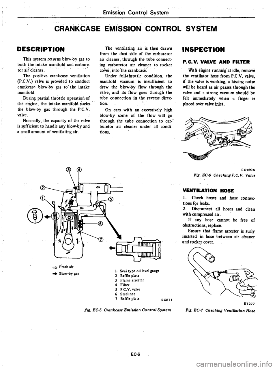
DESCRIPTION
This
system
returns
blow
by
gas
to
both
the
intake
manifold
and
carbure
tor
aitdeaner
The
positive
crankcase
ventilation
P
C
v
valve
is
provided
to
conduct
crankcase
blow
by
gas
to
the
intake
manifold
During
partial
throttle
operation
of
the
engine
the
intake
manifold
sucks
the
blow
by
gas
through
the
P
C
V
valve
Normally
the
capacity
of
the
valve
is
sufficient
to
handle
any
blow
by
and
a
small
amount
of
ventilating
air
L
J
J
o
I
Fresh
air
Blow
by
gas
The
ventilating
air
is
then
drawn
from
the
dust
side
of
the
carburetor
air
cleaner
through
the
tube
connect
ing
carburetor
air
cle
er
to
rocker
cover
into
the
crankcase
Under
full
throttle
condition
the
manifold
vacuum
is
insufficient
to
draw
the
blow
by
flow
through
the
valve
and
its
flow
goes
through
the
tube
connection
in
the
reverse
direc
tion
On
cars
with
an
excessively
high
blow
by
some
of
the
flow
will
go
through
the
tube
connection
to
car
buretor
air
cleaner
under
all
condi
tions
r
IiI
e
1
LJ
1
Seal
type
oil
level
gauge
2
DafOe
plate
3
Flame
arrester
4
Filter
5
P
C
V
valve
6
Steel
net
1
Baffle
plate
EC871
Fig
EC
5
Crankcase
Emis
ion
Control
Sy
tem
EC
6
INSPECTION
p
C
V
VALVE
AND
FILTER
With
ei
gine
runnirig
at
idle
remove
the
ventilator
hose
from
P
C
V
valve
if
the
valve
is
working
a
hissing
noise
wiD
be
heard
as
air
passes
through
the
valve
and
a
strong
vacuum
should
be
felt
irnniediately
when
a
fmger
is
placed
over
valve
inlet
EC139A
Fig
EC
6
Checking
PC
V
Vo
ve
VENTILATION
HOSE
I
Check
hoses
and
hose
connec
tions
for
ieaks
2
oisconn
ct
all
hoses
and
clean
with
compressed
air
If
any
hose
cannot
be
free
of
obstructions
replace
Ensure
that
flame
arrester
is
surly
inserted
in
hose
between
air
cleaner
and
rocker
rover
ET277
Fig
EC
7
Checking
Ventilation
Hose
Page 127 of 548
Emission
Control
System
EARLY
FUEL
EVAPORATIVE
E
FE
SYSTEM
DESCRIPTION
@
jl
D
W
o
0
0
UL
@
1
Intake
manifold
9
Screw
2
Stove
gasket
10
Thermostat
spring
3
Mar
fold
stove
11
Heat
control
valve
4
Heat
shield
plate
12
Control
valve
shaft
5
Snap
ring
13
Exhaust
manifold
6
Countczwcight
14
Cap
7
Key
15
Bushing
8
Stopper
pin
16
Coil
spring
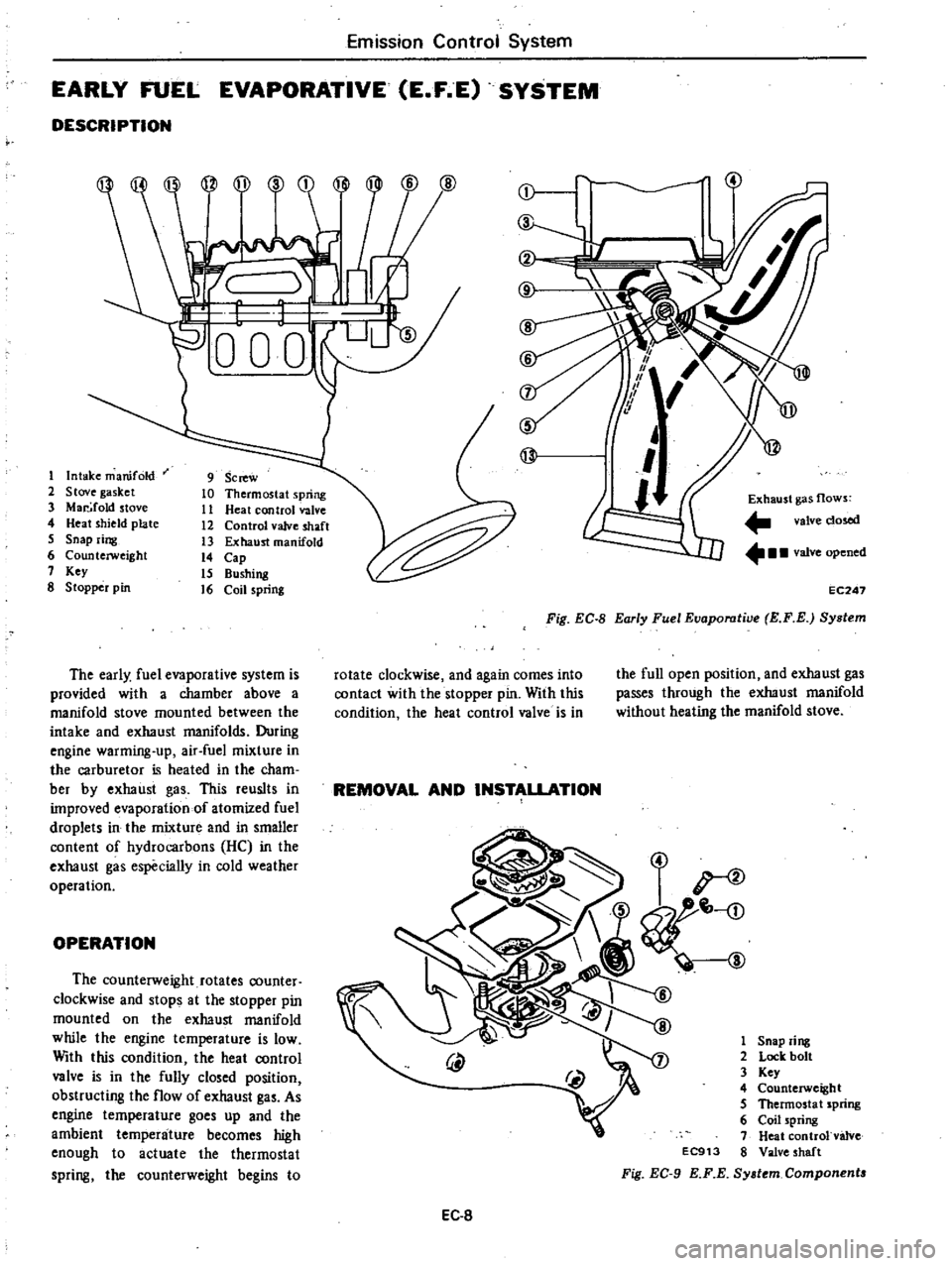
The
early
fuel
evaporative
system
is
provided
with
a
chamber
above
a
manifold
stove
mounted
between
the
intake
and
exhaust
manifolds
During
engine
warming
up
air
fuel
mixture
in
the
carburetor
is
heated
in
the
cham
ber
by
exhaust
gas
This
reuslts
in
improved
evaporation
of
atomized
fuel
droplets
in
the
mixture
and
in
smaller
content
of
hydrocarbons
HC
in
the
exhaust
gas
especially
in
cold
weather
operation
OPERATION
The
counterweight
rotates
counter
clockwise
and
stops
at
the
stopper
pin
mounted
on
the
exhaust
manifold
while
the
engine
temperature
is
low
With
this
condition
the
heat
control
valve
is
in
the
fully
closed
position
obstructing
the
flow
of
exhaust
gas
As
engine
temperature
goes
up
and
the
ambient
temperature
becomes
high
enough
to
actuate
the
thermostat
spring
the
counterweight
begins
to
j
@
l
7
1
1
5
If
@
I
Exhaust
gas
flows
valve
dosed
valve
opened
EC247
Fig
EC
8
Early
Fuel
Eaaporatiae
E
F
E
System
rotate
clockwise
and
again
comes
into
contact
with
the
stopper
pin
With
this
condition
the
heat
control
valve
is
in
the
full
open
position
and
exhaust
gas
passes
through
the
exhaust
manifold
without
heating
the
manifold
stove
REMOVAL
AND
INSTALLATION
1
Snap
ring
2
Lock
bolt
3
Key
4
Counterweight
5
Thermosta
t
spring
6
Coil
spring
7
Heat
controlvalve
EC913
8
Valve
shaft
Fig
EC
9
KF
E
Sy
tem
Component
EC
8
Page 128 of 548
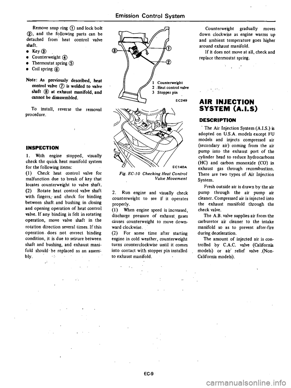
Remove
snap
ring
CD
and
lock
bolt
@
and
the
following
parts
can
be
detached
from
heat
control
valve
shaft
Key
ID
Counterweight
@
Thermostat
spring
@
Coil
spring
@
Note
As
previously
descnbed
heat
control
valve
j
is
welded
to
valve
shaft
@
at
exhaust
manifold
and
cannot
be
disassembled
To
install
reverse
the
removal
procedure
INSPECTION
1
With
engine
stopped
visually
check
the
quick
heat
manifold
system
for
the
following
items
I
Check
heat
control
valve
for
malfunction
due
to
break
of
key
that
locates
counterweight
to
valve
shaft
2
Rotate
heat
control
valve
shaft
with
fingers
and
check
for
binding
between
shaft
and
bushing
in
closing
and
opening
operation
of
heat
control
valve
If
any
binding
is
felt
in
rotating
operation
move
valve
shaft
in
the
rotation
direction
several
times
If
this
operation
does
not
correct
binding
condition
it
is
due
to
seizure
between
shaft
and
bushing
and
exhaust
mani
fold
should
be
replaced
as
an
assem
bly
Emission
Control
System
Counterweight
Heat
control
valve
Stopper
pin
EC249
Fig
EC
IO
Checking
Heat
Control
Valve
Movement
2
Run
engine
and
visually
check
counterweight
to
see
if
it
operates
properly
I
When
engine
speed
is
increased
discharge
pressure
of
exhaust
gases
causes
counterweight
to
move
down
ward
clockwise
2
For
some
time
after
starting
engine
in
cold
weather
counterweight
turns
counterclockwise
until
it
comes
into
contact
with
stopper
pin
installed
to
exhaust
manifold
EC
9
Counterweight
gradually
moves
down
clockwise
as
engine
warms
up
and
ambient
temperature
goes
higher
around
exhaust
manifold
If
it
does
not
move
at
all
check
and
replace
thermostat
spring
AIR
INJECTION
SYSTEM
A
I
S
DESCRIPTION
The
Air
Injection
System
A
I
S
is
adopted
on
U
S
A
models
except
FU
models
and
injects
compressed
air
secondary
air
coming
from
the
air
pump
into
the
exhaust
port
of
the
cylinder
head
to
reduce
hydrocarbons
He
and
carbon
monoxide
CO
in
exhaust
gas
through
recombustion
There
are
two
types
of
Air
Injection
System
Fresh
outside
air
is
drawn
by
the
air
pump
through
the
air
pump
air
cleaner
Compressed
air
is
injected
into
the
exhaust
manifold
through
the
check
valve
The
A
B
valve
supplies
air
from
the
carburetor
air
cleaner
to
the
intake
manifold
so
as
to
prevent
after
fire
during
deceleration
The
amount
of
injected
air
is
con
trolled
by
C
A
C
valve
California
models
or
air
relief
valve
Non
California
models