service indicator DATSUN 210 1979 Service Manual
[x] Cancel search | Manufacturer: DATSUN, Model Year: 1979, Model line: 210, Model: DATSUN 210 1979Pages: 548, PDF Size: 28.66 MB
Page 21 of 548

CHECKING
AND
ADJUSTING
CARBURETOR
IDLE
RPM
AND
MIXTURE
RATIO
WARNING
a
0
n
a
utomatic
transmission
models
checks
should
be
per
formed
with
the
lever
shifted
to
the
0
position
Be
sure
to
engage
parking
brake
and
to
lock
both
front
and
rear
wheels
with
wheel
chocks
b
Oepress
brake
pedal
while
ac
celerating
the
engine
to
prevent
forward
surge
of
car
c
After
idle
adjustment
has
been
made
shift
the
lever
to
the
N
or
P
positfon
and
remove
wheel
chocks
CAUTION
00
not
attempt
to
screw
the
idle
adjusting
screw
down
completely
00
ing
so
could
cause
damage
to
tip
which
in
turn
will
tend
to
cause
malfunctions
Note
a
When
measuring
CO
percentage
in
sert
probe
into
tail
pipe
more
than
40
cm
15
7
in
b
In
thee
case
of
air
conditioner
e
quipped
models
the
idle
adjust
ment
should
be
carried
out
while
the
air
conditioner
is
OFF
c
When
making
idle
adjustment
do
not
removt
air
cleaner
CO
Idle
adJustment
with
CO
meter
Idle
mixture
adjustment
requires
the
use
of
a
CO
meter
especially
for
California
models
When
preparing
to
adjust
idle
mixture
it
is
essential
to
have
the
meter
thoroughly
warmed
up
and
calibrated
1
Check
carburetor
pipes
for
proper
connection
2
Warm
up
engine
until
water
tern
perature
indicator
points
to
the
middle
of
gauge
The
procedure
to
warm
up
J
Engine
Tune
up
engine
is
not
specifically
recom
mended
Either
driving
car
or
operat
ing
engine
at
no
load
will
be
good
3
Make
sure
that
water
temperature
indicator
points
to
the
middle
Further
keep
engine
running
at
about
2
000
rpm
for
about
5
minutes
without
applying
load
to
engine
in
order
to
stabilize
engine
condition
Engine
hood
should
be
open
4
Run
engine
for
about
10
minutes
at
idling
speed
During
this
10
minutes
proceed
as
described
in
steps
5
to
9
below
5
I
Disconnect
air
hose
from
air
check
valve
and
install
cap
on
air
check
valve
Except
Canada
and
FU
models
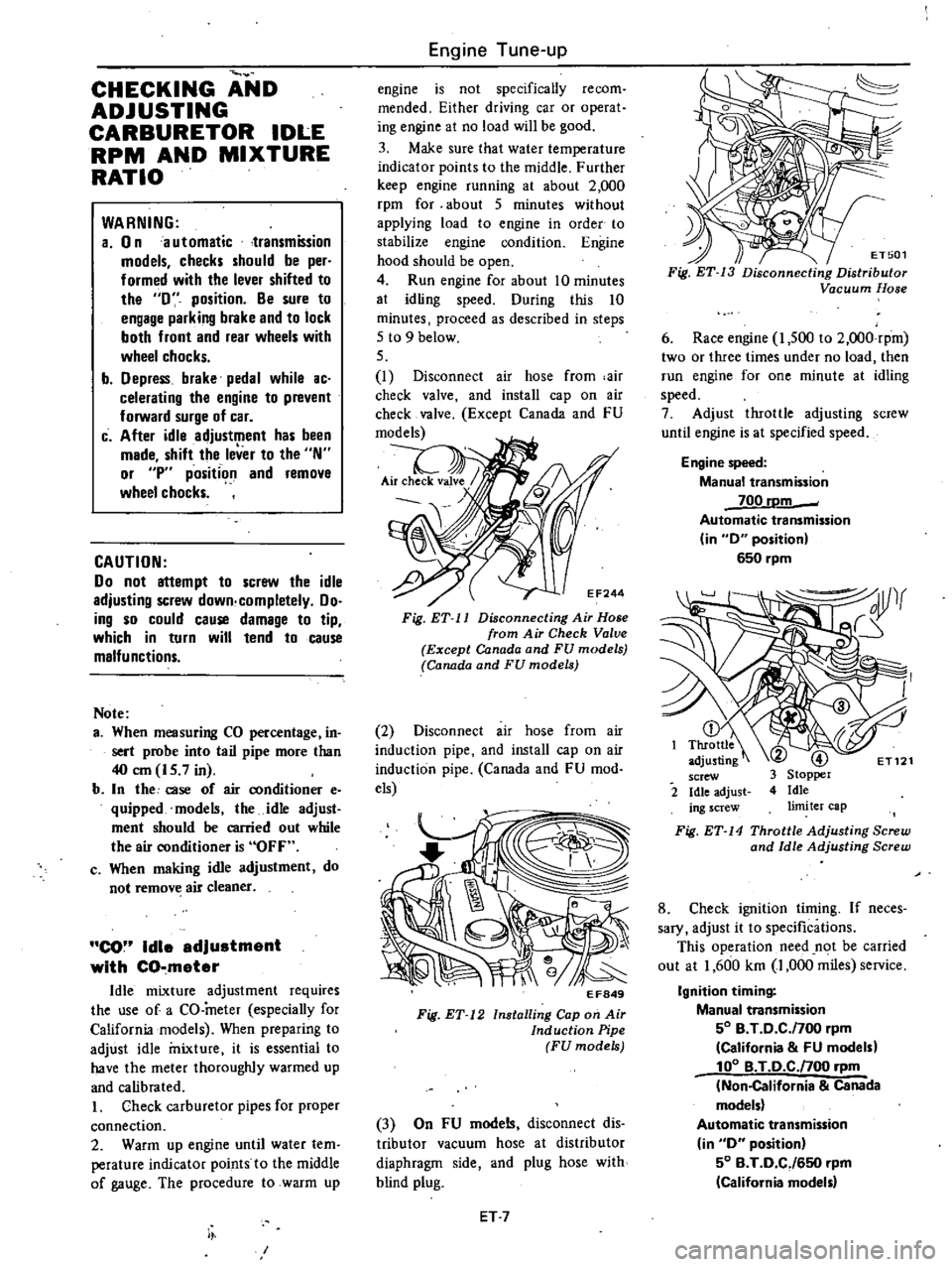
EF244
Fig
ET
11
Disconnecting
Air
Hose
from
Air
Check
Valve
Except
Canada
and
FU
models
Canada
and
FU
models
2
Disconnect
air
hose
from
air
induction
pipe
and
install
cap
on
air
induction
pipe
Canada
and
FU
mod
els
EF849
Fig
ET
12
Installing
Cap
on
Air
Induction
Pipe
FU
models
3
On
FU
models
disconnect
dis
tributor
vacuum
hose
at
distributor
diaphragm
side
and
plug
hose
with
blind
plug
ET
7
ET501
Fig
ET
13
Disconnecting
Distributor
Vacuum
Hose
6
Race
engine
I
500
to
2
OOO
rpm
two
or
three
times
under
no
load
then
run
engine
for
one
minute
at
idling
speed
7
Adjust
throttle
adjusting
screw
until
engine
is
at
specified
speed
Engine
speed
Manual
transmission
700
rDm
Automatic
transmission
in
0
position
650
rpm
2
Fig
ET
14
Throttle
Adjusting
Screw
and
Idle
Adjusting
Screw
8
Check
ignition
timing
If
neces
sary
adjust
it
to
specifications
This
operation
need
n
t
be
carried
out
at
1
600
km
1
000
miles
service
Ignition
timing
Manual
transmission
50
B
T
0
C
f700
rpm
California
FU
models
100
B
T
O
C
noo
rpm
Non
California
Canada
models
Automatic
transmission
in
0
position
50
B
T
0
CJ650
rpm
California
model
Page 22 of 548

SO
B
T
D
C
650
rpm
Non
California
models
except
Canada
100
B
T
0
C
650
rpm
Canada
models
Note
On
FU
models
ignition
timing
t
under
a
con4ition
where
distnoutor
vacuum
hose
is
discon
nected
9
On
FU
models
proceed
as
fol
lows
I
Remove
blind
plug
from
dis
tributor
vacuum
hose
and
connect
hose
to
distributor
diaphragm
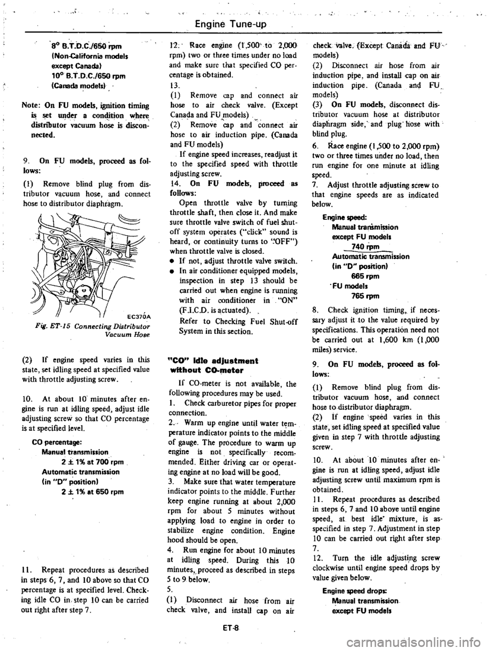
EC370A
Fig
ET
15
Connecting
Distributor
Vacuum
Hose
2
If
engine
speed
varies
in
this
state
set
idling
speed
at
specified
value
with
throttle
adjusting
screw
10
At
about
10
minutes
after
en
gine
is
run
at
idling
speed
adjust
idle
adjusting
screw
so
that
CO
percentage
is
at
specified
level
CO
percentage
Manual
transmission
2
t
1
at
700
rpm
Automatic
transmission
in
0
position
2
t
1
at
650
rpm
II
Repeat
procedures
as
described
in
steps
6
7
and
10
above
so
that
CO
percentage
is
at
specified
level
Check
ing
idle
CO
in
step
10
can
be
carried
out
right
after
step
7
Engine
Tune
up
11
Race
engine
1
500
to
2
000
rpm
two
or
three
times
under
no
load
and
make
sure
that
specified
CO
per
centage
is
obtained
13
I
Remove
cap
and
connect
air
hose
to
air
check
valve
Except
Canada
and
FU
models
2
Remove
p
and
connect
air
hose
to
air
induction
pipe
Canada
and
FU
models
If
engine
speed
increases
readjust
it
to
the
specified
speed
with
throttle
adjusting
screw
14
On
FU
models
proceed
as
follows
Open
throttle
valve
by
tuming
throttle
shaft
then
close
it
And
make
sure
throttle
valve
switch
of
fuel
shut
off
system
operates
click
sound
is
heard
or
continuity
turns
to
OFF
when
throttle
valve
is
closed
If
not
adjust
throttle
valve
switch
In
air
conditioner
equipped
models
inspection
in
step
13
should
be
carried
out
when
engine
is
running
with
air
conditioner
in
ON
F
l
CD
is
actuated
Refer
to
Checking
Fuel
Shut
off
System
in
this
section
CO
Idle
adjuatment
without
CO
mater
If
CO
meter
is
not
available
the
following
procedures
may
be
used
I
Check
carburetor
pipes
for
proper
comiection
2
Warm
up
engine
until
water
t
m
perature
indicator
points
to
the
middle
of
gauge
The
procedure
to
warm
up
engine
is
not
specifically
recom
mended
Either
driving
car
or
operat
ing
engine
at
no
load
will
be
good
3
Make
sure
that
water
temperature
indicator
points
to
the
middle
Further
keep
engine
running
at
about
2
000
rpm
for
about
5
minutes
without
applying
load
to
engine
in
order
to
stabilize
engine
condition
Engine
hood
should
be
open
4
Run
engine
for
about
10
minutes
at
idling
speed
During
this
10
minutes
proceed
as
described
in
steps
5
to
9
below
5
I
Disconnect
air
hose
from
air
check
valve
and
install
cap
on
air
ET
8
check
nlve
Except
Canada
and
FU
models
2
Disconnect
air
hose
from
air
induction
pipe
and
install
cap
on
air
induction
pipe
Canada
an
FU
models
3
On
FU
models
disconnect
dis
tributor
vacuum
hose
at
distributor
diaphragm
ide
and
plug
hose
with
blind
plug
6
Race
engine
1
500
to
2
000
rpm
two
or
three
times
under
no
load
then
run
engine
for
one
minute
at
idling
speed
7
Adjust
throttle
adjusting
screw
to
that
engine
speeds
are
as
indicated
below
Engine
speed
Manual
tra
mi
ion
except
FU
models
740
rpm
Automatic
transmission
in
0
position
665
rpm
FU
models
765
rpm
8
Check
ignition
timing
if
neces
sary
adjust
it
to
the
value
required
by
specifications
This
operation
need
not
be
carried
out
at
1
600
km
1
000
miles
service
9
On
FU
models
proceed
as
fol
lows
I
Remove
blind
plug
from
dis
tributor
vacuum
hose
and
connect
hose
to
distributor
diaphragm
2
If
engine
speed
varies
in
this
state
set
idling
speed
at
specified
value
given
in
step
7
with
throttle
adjusting
screw
10
At
about
10
minutes
after
en
gine
is
run
at
idling
speed
adjust
idle
adjusting
screw
until
maximum
rpm
is
obtained
II
Repeat
procedures
as
described
in
steps
6
7
and
10
above
until
engine
speed
at
best
idle
mixture
is
as
specified
in
step
7
Adjustment
in
step
10
can
be
carried
out
right
after
step
7
12
Turn
the
idle
adjustIng
screw
clockwise
until
engine
speed
drops
by
value
given
below
Engine
speed
drops
Manual
transmission
except
FU
models
Page 47 of 548

Out
of
ound
X
Y
Less
than
0
03
mm
10
0012
in
Taper
A
B
Less
than
0
03
mm
0
0012
in
Out
of
round
X
Y
Taper
A
B
B
o
r
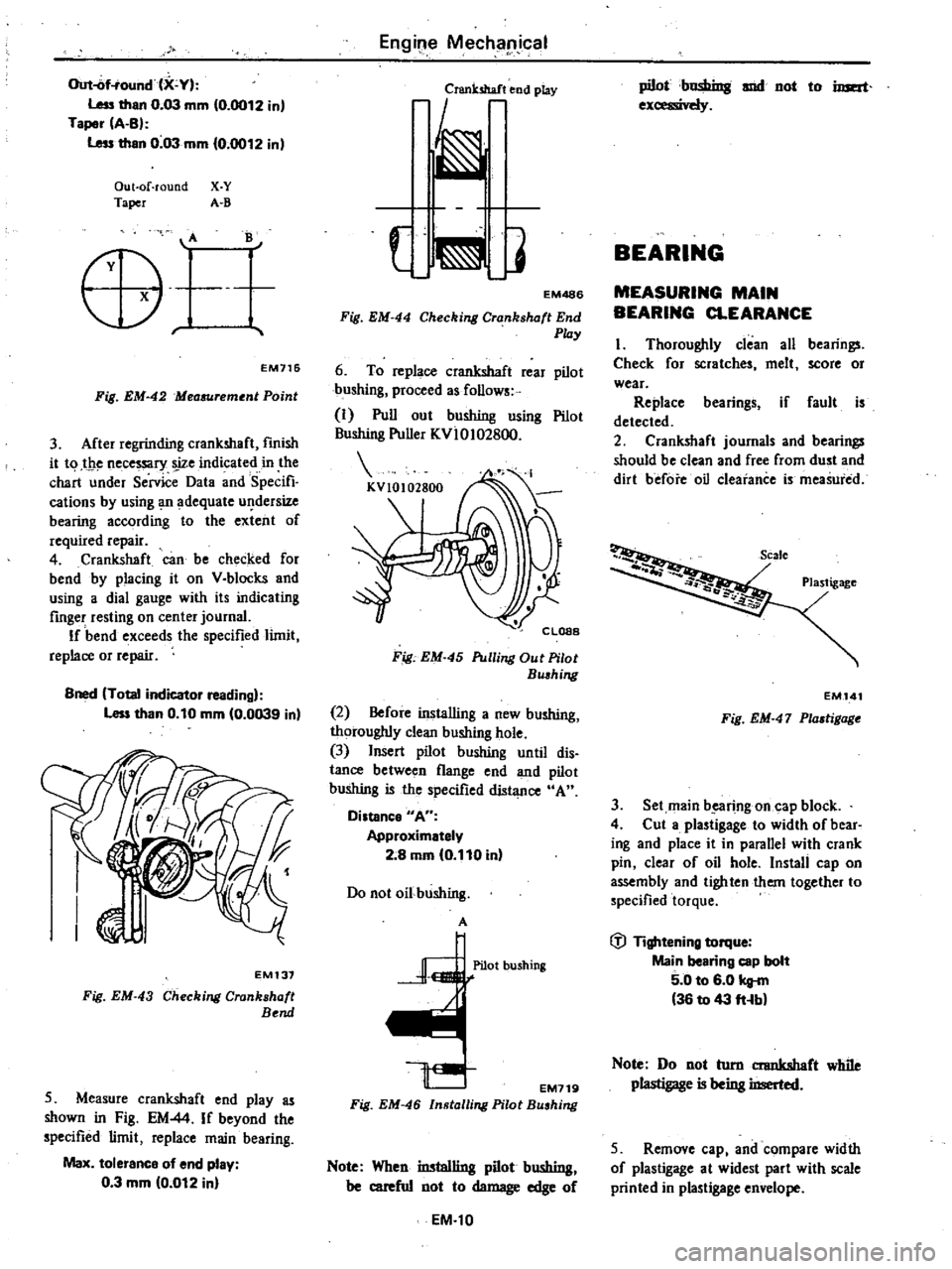
EM716
Fig
EM
42
Mea6Urement
Point
3
After
regrinding
crankshaft
fmish
it
t
1
t
1e
necessary
s
ize
indicated
in
the
chart
under
Service
Data
and
Specifi
cations
by
using
Ill
adequate
u
dersize
bearing
according
to
the
extent
of
required
repair
4
Crankshaft
can
be
checked
for
bend
by
placing
it
on
V
blocks
and
using
a
dial
gauge
with
its
indicating
finger
resting
on
center
journal
If
bend
exceeds
the
specified
limit
replace
or
repair
Bned
Total
indicator
reading
Less
than
0
10
mm
0
0039
in
EM137
Fig
EM
43
Checking
Crankshaft
Bend
5
Measure
crankshaft
end
play
as
shown
in
Fig
EM
44
If
beyond
the
specified
limit
replace
main
bearing
Max
tolerance
of
end
play
0
3
mm
10
012
in
Engil
e
Mechllpjcal
Crsnk5haf
end
play
EM486
Fig
EM
44
Checking
Crankshaft
End
Play
6
To
replace
crankshaft
rear
pilot
bushing
proceed
as
follows
1
Pull
out
bushing
using
Pilot
Bushing
Puller
KvloI02800
Fig
EM
45
Pulling
Out
Pilot
Bushing
2
Before
installing
a
new
bushing
thoroughly
clean
bushing
hole
3
Insert
pilot
bushing
until
dis
tance
between
flange
end
and
pilot
bushing
is
the
specified
diJ1l
nce
A
Distance
A
Approximetely
2
8
mm
0
110
in
Do
not
oil
bushing
A
Pilot
bushing
EM719
Fig
EM
46
Installing
Pilot
Bushing
Note
When
installing
pilot
bushing
be
careful
not
to
damage
edge
of
EM
l0
pilot
C
snd
not
to
imat
1
1
1
BEARING
MEASURING
MAIN
BEARING
CLEARANCE
I
Thoroughly
clean
all
bearings
Check
for
scratches
melt
score
or
wear
Replace
bearings
if
fault
is
detected
2
Crankshaft
journals
and
bearings
should
be
clean
and
free
from
dust
and
dirt
before
oil
Clearance
is
meaSured
Plastigage
EM
141
Fig
EM
47
Plastigage
3
Set
main
b
e1lfing
on
cap
block
4
Cut
a
plastigage
to
width
of
bear
ing
and
place
it
in
parallel
with
crank
pin
clear
of
oil
hole
Install
cap
on
assembly
and
tighten
them
together
to
specified
torque
fj
Tightening
torque
Main
bearing
cop
bolt
5
0
to
6
0
kg
m
36
to
43
fHb
Note
Do
not
turn
crankshaft
while
plastigage
is
being
inserted
5
Remove
cap
and
compare
width
of
plastigage
at
widest
part
with
scale
printed
in
plastigage
envelope
Page 287 of 548

Fig
AT
70
MeG6Uring
Clearonce
Clearance
between
seal
ring
and
ring
groove
Stendard
0
04
to
0
16
mm
10
002
to
0
006
in
I
31earance
Seal
ring
w
I
J
7
r
11
AT1
5
II
Fig
AT
71
MeG6Uring
Clearance
As
mblr
L
Set
up
pump
housing
with
inner
and
outer
pump
gears
on
it
2
Using
Oil
Pump
Assembling
Gauge
ST2SS80001
instan
pump
cover
to
pump
houaing
AT166
Fig
AT
72
Centering
Oil
Pump
3
Temporarily
tighten
pump
secur
ing
bolts
4
Set
the
cunout
of
oil
pump
cover
within
specified
total
indicator
read
ing
Automatic
Transmission
Total
indicator
reading
Lell
than
0
07
mm
10
0028
inl
ST2SSBOOOl
AT264
Fig
AT
73
Me
ring
Runout
S
Tighten
pump
securing
bolts
to
specified
torque
r
Tightening
torque
Oil
pump
housing
to
oil
pump
cover
0
6
to
0
8
kg
m
14
3
to
5
8
ft
Ibl
Note
Be
sure
to
align
con
ter
housini
securing
bolt
holes
6
Again
check
the
runout
of
oil
pump
cover
Note
When
former
Oil
Pump
As
sembling
Gauge
is
to
be
used
make
a
screw
hole
in
side
of
it
PLANETARY
CARRIER
The
planetary
carrier
cannot
be
divided
into
its
individual
components
If
any
part
of
component
is
defec
tive
replace
the
carrier
as
a
unit
In
p
ctlon
Check
clearance
between
pinion
washer
and
planetary
carrier
with
a
feeler
Standard
d
0
20
to
0
70
mm
0
008
to
0
028
in
AT
35
uan
r
J
II
I
AT1S7
Fig
AT
74
MeG6Uring
Pinion
Waaher
to
CanUr
Clearance
Replace
if
over
0
80
mm
0
031
in
CONTROL
VALVE
Tlte
control
valve
assembly
consists
of
many
precision
parts
and
requires
extreme
care
when
it
has
to
be
re
moved
and
serviced
It
is
good
practice
to
place
parts
in
a
part
rack
so
that
they
can
be
reassembled
in
valve
body
in
their
proper
positions
Added
care
should
also
be
exercised
to
prevent
springs
and
other
small
parts
from
being
sca
ttered
and
lost
Before
assembly
dip
all
parts
in
clean
automatic
transmission
fluid
and
check
to
be
certain
that
they
are
free
of
lint
and
other
minute
particles
If
clutch
or
band
is
burnt
or
if
oil
becomes
fouled
the
control
valve
as
sembly
should
be
disassembled
and
flushed
DI
mblr
I
Remove
bolts
and
nuts
which
retain
oil
strainer
Bolts
may
be
re
moved
with
a
screwdriver
but
it
is
recommended
that
Hexagon
Wrench
lIT61000S00
and
Spinner
Handle
lIT623S0000
b
used