Electrical DATSUN 210 1979 Workshop Manual
[x] Cancel search | Manufacturer: DATSUN, Model Year: 1979, Model line: 210, Model: DATSUN 210 1979Pages: 548, PDF Size: 28.66 MB
Page 195 of 548

Engine
Electrical
System
IV
IGNITION
CIRCUIT
When
engine
does
not
start
If
there
is
no
problem
in
fuel
system
ignition
system
should
be
checked
This
can
be
easily
done
by
detaching
a
high
tension
cable
from
distributor
starting
engine
and
ob
serving
oondition
of
spark
that
occurs
between
high
tension
cable
and
engine
block
After
checking
this
repair
as
necessary
tery
and
anti
dieseliilg
wlenoid
valve
connector
to
cuI
off
supply
of
fuel
10
engine
Then
observe
the
condition
of
sparks
while
starter
motor
is
in
operation
Note
Turn
ignilion
switch
off
and
disconnect
ground
cable
from
bat
Condition
Location
Probable
cause
Corrective
action
No
spark
at
all
Distributor
Breakage
of
lead
wire
on
low
tension
side
Repair
Poor
insulation
of
cap
and
rotor
head
Replace
Open
pick
up
coil
Replace
Air
gap
wider
than
specification
Adjust
Ignition
coil
Wire
breakage
or
short
circuit
of
coil
Replace
with
new
one
High
tension
cable
Wire
coming
off
Repair
Faulty
insulation
Replace
IC
ignition
unit
Faulty
IC
ignition
unit
Replace
Breakage
of
circuit
Replace
Detached
connection
Repair
Spark
length
Spark
plugs
Spark
plug
gap
too
wide
Correct
or
replace
More
than
6
mm
Too
much
carbon
Clean
or
replace
0
24
in
Broken
neck
of
insulator
Replace
Expiration
of
plug
life
Replace
Distributor
Air
gap
too
wide
Correct
IC
ignition
unit
Faulty
IC
ignition
unit
Replace
Breakage
of
circuit
Replace
Detached
connection
Repair
EE
37
Page 196 of 548

2
Engine
rotates
but
does
not
run
smoothly
This
may
be
caused
by
the
ignition
Condition
Location
Engine
misses
Distributor
Ignition
coil
High
tension
cable
Spark
plugs
IC
ignition
unit
Engine
causes
knocking
very
often
Distributor
Spark
plugs
Engine
does
not
deliver
enough
power
Distributor
Spark
plugs
Engine
Electrical
System
system
or
other
engine
conditions
not
related
to
ignition
system
Therefore
first
complete
inspection
of
ignition
system
should
be
carried
out
Probable
cause
Foreign
matter
onpicl
up
coil
Improper
air
gap
Leak
of
electricity
at
cap
and
rotor
head
Breakage
of
pick
up
coil
lead
wire
Worn
or
shaky
breaker
plate
Worn
or
shaky
distributor
driVing
shaft
Layer
short
circuit
or
inferior
quality
coil
Deterioration
of
insulation
with
cense
quenlleak
of
electricity
Fouled
Leak
of
electricity
at
upper
porcelain
insulator
Spark
plug
gap
too
narrow
Faulty
IC
ignition
unit
Breakage
of
circuit
Detached
connection
Improper
ignition
timing
too
advanced
Coming
off
or
breakage
of
governor
spring
Worn
pin
or
hole
of
governor
Burnt
too
much
Improper
ignition
timing
too
retarded
Improper
functioning
governor
Foreign
particles
stuck
in
air
gap
Fouled
EE
38
Corrective
action
Clean
Correct
Repair
or
replace
Replace
Replace
assembly
Replace
aSsembly
Replace
with
good
one
Replace
Clean
Repair
or
replace
Correct
or
replace
Replace
Replace
Repair
Correct
Correct
or
replace
Replace
Replace
Correct
Replace
assembly
Clean
Clean
Page 201 of 548
INSTALLATION
Install
in
the
reverse
order
of
re
moval
observing
the
following
Note
When
inslal1ing
be
sure
to
check
thaI
electrical
harnesses
are
connected
ly
1
When
installing
first
secure
rear
engine
mounting
member
to
body
2
Refer
to
applicable
section
when
installing
and
adjusting
any
parts
Adjust
clutch
pedal
free
travel
Re
fer
to
Clutch
Pedal
Free
Travel
Section
CL
for
installation
and
adjustment
Adjust
accelerator
control
system
Refer
to
Engine
Control
System
Section
FE
for
adjustment
For
installation
of
air
conditioner
compressor
and
belt
adjustment
Refer
to
Idler
Pulley
and
Com
pressor
Drive
Belt
for
adjustment
of
belt
tension
3
When
installing
exhaust
front
tube
on
exhaust
manifold
be
sure
to
use
new
gasket
4
When
installing
hood
following
engine
installation
be
sure
that
it
is
properly
centered
and
that
hood
lock
operates
securely
Refer
to
Hood
See
tion
BF
for
adjustment
Engine
Removal
Installation
ENGINE
MOUNTING
INSULATOR
FRONT
INSULATOR
Removal
Disconnect
battery
ground
cable
2
Suspend
engine
with
wire
or
chain
3
Remove
front
engine
mounting
insulator
lower
and
upper
nuts
on
both
sides
4
Make
sure
that
wire
or
chain
used
to
suspend
engine
is
positioned
prqper
ly
so
that
no
load
is
applied
to
insulators
and
remove
nuts
complete
ly
5
Lift
up
engine
and
separate
in
sulators
from
engine
mounting
rack
ets
Inspection
If
there
is
damage
deterioration
or
separation
of
bounded
surface
re
place
Installation
Install
front
insulators
in
reverse
sequence
of
removal
noting
the
fol
lowing
1
Do
not
confuse
right
and
left
insulators
R
right
side
or
L
left
side
identification
mark
is
stamp
ed
on
each
insulator
2
Install
front
insulator
so
that
ER
5
position
pin
is
projected
upward
3
Tighten
the
bolts
and
nut
correct
ly
and
securely
See
Fig
ER
I
REAR
INSULATOR
Removal
l
Support
transmission
weight
with
ajack
2
Remove
nuts
securing
rear
engine
mounting
insulator
to
mounting
mem
ber
3
Remove
bolts
connecting
rear
en
gine
mounting
insulator
to
transmis
sion
reaf
extension
housing
4
Jack
up
the
transmission
a
little
and
remove
insulator
Inspection
If
there
is
damage
deterioration
or
separation
of
mating
surface
replace
Installation
Install
rear
engine
mounting
mem
ber
and
insulator
in
reverse
order
of
removal
noting
the
following
I
Install
insulator
in
place
so
that
direction
of
mounted
insulator
is
same
as
that
in
Fig
ER
2
Tighten
nuts
and
bolts
correctly
and
securely
As
for
tightening
torque
see
Fig
ER
l
Page 255 of 548

Automatic
Transmission
HYDRAULIC
CONTROL
UNIT
AND
VALVES
The
hydraulic
or
a
tomatic
control
system
is
comprised
of
four
4
basic
groups
the
pressure
supply
system
the
pressure
regulating
system
the
flow
control
valves
and
the
friction
elements
PRESSURE
SUPPLY
SYSTEM
The
pressure
supply
system
consists
of
a
gear
type
oil
pwnp
driven
by
the
engine
through
the
torque
converter
The
pump
provides
pressure
for
aU
hydraulic
and
lubrication
needs
PRESSURE
REGULATOR
VALVES
The
pressure
regulating
valves
con
trol
the
output
pressure
of
the
oil
pump
Pre
ure
rellulator
valve
The
pressure
regulator
valve
con
trois
mainline
pressure
based
on
throttle
opening
for
the
operation
of
the
band
clutches
and
brake
Governor
valve
The
governor
valve
transmits
re
gulated
pressure
based
on
car
peed
to
the
shift
valves
to
control
upshifts
and
downshifts
Vacuum
throttle
valve
The
vacuum
throttle
valve
transmits
regulated
pressure
based
on
engine
load
vacuum
This
pressure
controls
the
pressure
regulator
valve
Also
this
pressure
is
applied
to
one
end
of
the
shift
valves
in
opposition
to
governor
pressure
which
acts
on
the
other
end
of
the
shift
valves
controlling
upshift
and
downshift
speeds
FLOW
CONTROL
VALVES
Manual
valve
The
manual
valve
is
moved
manual
Iy
by
the
car
operator
to
select
the
different
drive
ranges
1
2
ShHt
valve
The
1
2
shift
valve
automaticaIly
shifts
the
transmission
from
first
to
second
or
from
second
to
first
depend
ing
upon
governor
and
throttle
pres
sure
along
with
accelerator
position
solenoid
downshift
valve
See
Hy
draulic
Control
Circuits
Drive
2
2
3
ShHt
valve
The
2
3
shift
valve
automaticaIly
shifts
the
transmission
from
second
to
top
gear
or
from
top
to
second
de
pending
upon
governor
and
throttle
pressure
or
accelerator
position
sole
noid
downshift
valve
See
Hydraulic
Control
Circuits
Drive
3
Range
2
3
Tlmlnll
valve
For
2
3
shifts
a
restrictive
orifice
slows
the
application
fluid
to
the
front
clutch
while
the
slower
reacting
band
is
allowed
to
release
This
prevents
a
hard
2
3
or
3
2
shift
Under
heavy
load
however
the
engine
will
tend
to
run
away
during
the
2
3
or
3
2
shift
pause
therefore
a
2
3
timing
valve
using
throttle
and
governor
pressure
is
used
to
bypass
the
restrictive
orifice
during
such
heavy
load
conditions
Solenoid
down
hHt
valve
The
solenoid
downshift
valve
is
activated
electrically
when
the
ac
celerator
is
f1oor
d
causing
a
forced
downshift
from
top
to
second
top
to
first
or
second
to
first
gear
depending
upon
car
speed
governor
pressure
AT
3
Pre
ure
modified
valve
The
pressure
modifier
valve
assists
the
mainline
pressure
regulator
valve
in
lowering
mainline
pressure
during
high
speed
light
load
conditions
such
as
steady
speed
cruise
Governor
pres
sure
working
against
a
spring
opens
the
valve
which
aUows
modified
throt
tle
pressure
to
work
against
the
pres
sure
regulator
valve
spring
lowering
mainline
pressure
Lower
operating
pressure
under
light
load
reduces
oil
temperature
and
increases
transmis
sian
life
Throttle
back
up
valve
The
throttle
back
up
valve
assists
the
vacuum
throttle
valve
to
increase
line
pressure
when
the
manual
valve
is
shifted
either
to
2
or
I
range
Second
lock
valve
The
second
lock
valve
is
used
to
bypa
the
1
2
shift
valve
to
maintain
the
band
apply
pressure
in
2
posi
tion
The
valve
is
also
used
as
an
oil
passage
for
the
1
2
shift
valve
band
apply
pressure
in
D2
D3
and
12
Range
CLUTCHES
AND
BAND
SERVOS
The
servo
pistons
of
the
clutches
low
reverse
brake
and
band
are
moved
hydraulically
to
engage
the
clutches
brake
and
apply
the
band
The
clutch
and
brake
istons
are
released
by
spring
tension
and
band
piston
is
released
by
spring
tension
and
hy
draulic
pressure
Page 446 of 548
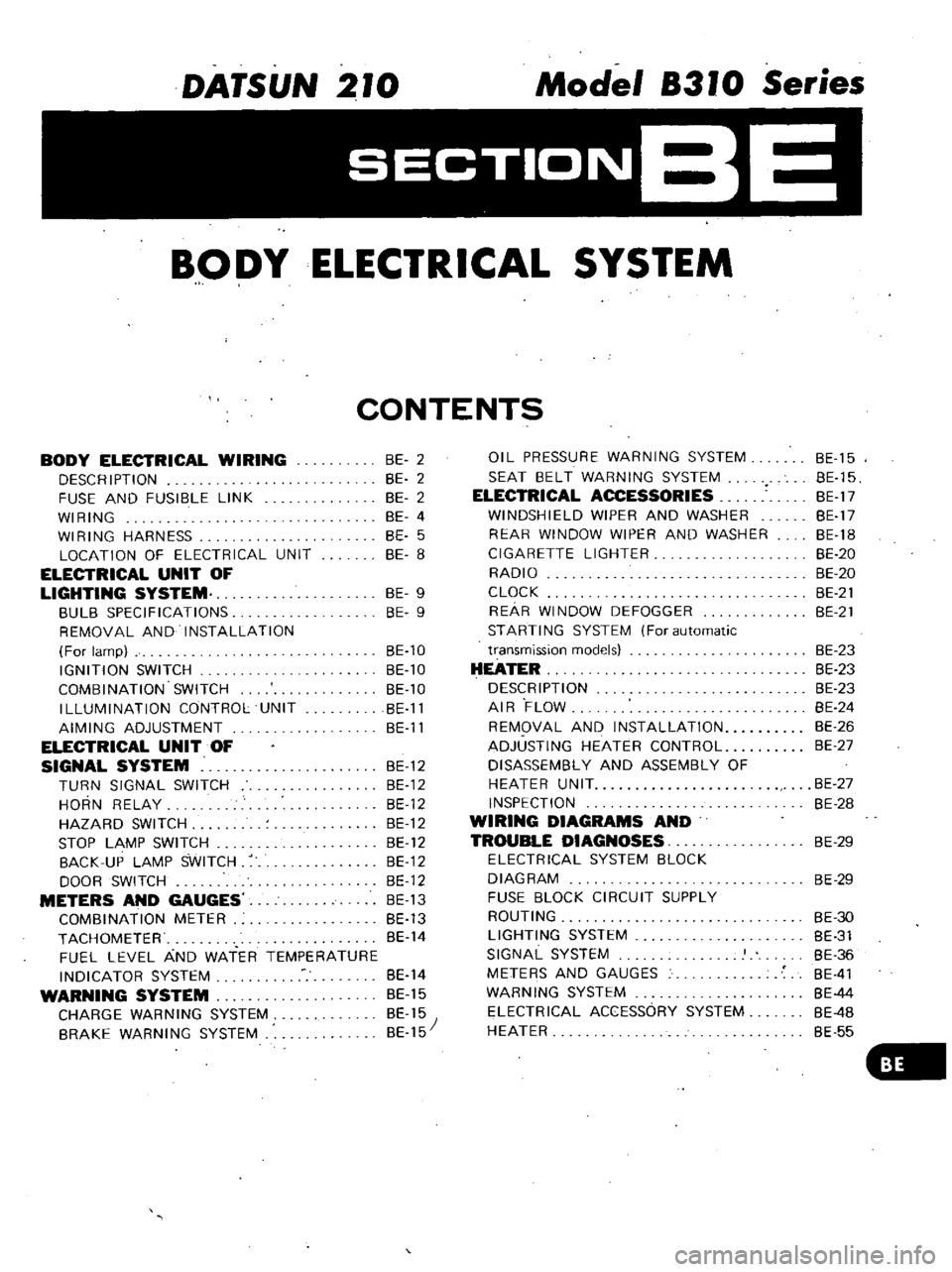
DATSUN
210
Model
8310
Series
SECTIONBE
BODY
ELECTRICAL
SYSTEM
CONTENTS
BODY
ELECTRICAL
WIRING
DESCRIPTION
FUSE
AND
FUSIBLE
LINK
WIRING
WIRING
HARNESS
LOCATION
OF
ELECTRICAL
UNIT
ELECTRICAL
UNIT
OF
LIGHTING
SYSTEM
BULB
SPECIFICATIONS
REMOVAL
AND
INSTALLATION
For
lamp
IGNITION
SWITCH
COMBINATION
SWITCH
ILLUMINATION
CONTROL
UNIT
AIMING
ADJUSTMENT
ELECTRICAL
UNIT
OF
SIGNAL
SYSTEM
BE
12
TURN
SIGNAL
SWITCH
BE
12
HORN
RELAY
BE
12
HAZARD
SWITCH
BE
12
STOP
LAMP
SWITCH
BE
12
BACK
UP
LAMP
SWITCH
BE
12
DOOR
SWITCH
BE
12
METERS
AND
GAUGES
BE
13
COMBINATION
METER
BE
13
TACHOMETER
BE
14
FUEL
LEVEL
AND
WATER
TEMPERATURE
INDICATOR
SYSTEM
BE
14
WARNING
SYSTEM
BE
15
CHARGE
WARNING
SYSTEM
BE
15
BRAKE
WARNING
SYSTEM
BE
15
BE
2
BE
2
BE
2
BE
4
BE
5
BE
8
BE
9
BE
9
BE
10
BE
10
BE
10
BE
11
BE
11
OIL
PRESSURE
WARNING
SYSTEM
SEAT
BELT
WARNING
SYSTEM
ELECTRICAL
ACCESSORIES
WINDSHIELD
WIPER
AND
WASHER
REAR
WINDOW
WIPER
AND
WASHER
CIGARETTE
LIGHTER
RADIO
CLOCK
REAR
WINDOW
DEFOGGER
STARTING
SYSTEM
For
automatic
transmission
models
HEATER
DESCRIPTION
AIR
FLOW
REMOVAL
AND
INSTALLATION
ADJUSTING
HEATER
CONTROL
DISASSEMBLY
AND
ASSEMBLY
OF
HEATER
UNIT
INSPECTION
WIRING
DIAGRAMS
AND
TROUBLE
DIAGNOSES
ELECTRICAL
SYSTEM
BLOCK
DIAGRAM
FUSE
BLOCK
CIRCUIT
SUPPLY
ROUTING
LIGHTING
SYSTEM
SIGNAL
SYSTEM
METERS
AND
GAUGES
WARNING
SYSTEM
ELECTRICAL
ACCESSORY
SYSTEM
HEATER
BE
15
BE
15
BE
17
BE
17
BE
18
BE
20
BE
20
BE
21
BE
21
BE
23
BE
23
BE
23
BE
24
BE
26
BE
27
BE
27
BE
28
BE
29
BE
29
BE
30
BE
31
BE
36
BE
41
BE
44
BE
4B
BE
55
Page 447 of 548
DESCRI
PTI
ON
Cabl
are
covered
with
color
coded
vinyl
for
easy
identification
In
the
wiring
diagram
olors
are
indicated
by
one
or
two
alphabetical
letters
It
is
recommended
that
the
battery
be
disconnected
before
performing
any
electrical
service
other
than
bulb
or
fuse
replacement
In
addition
to
fuses
a
fusible
link
has
been
installed
to
protect
wiring
Circuit
system
Starting
and
ignition
system
Charging
system
Lighting
system
Signal
system
Instrument
system
Others
Grounding
system
The
main
cable
of
each
system
is
generally
coded
with
a
single
color
These
colors
are
represented
by
such
letters
as
G
W
or
Br
Minor
items
of
each
circuit
s
terminal
are
coded
with
a
two
tone
color
as
follows
BW
Black
with
white
stripe
LgR
Light
green
with
red
stripe
Body
ectrical
System
BODY
ELECTRICAL
WIRING
The
fusible
link
functions
almost
the
same
as
a
fuse
though
its
characteris
tics
are
slightly
different
than
normal
fuses
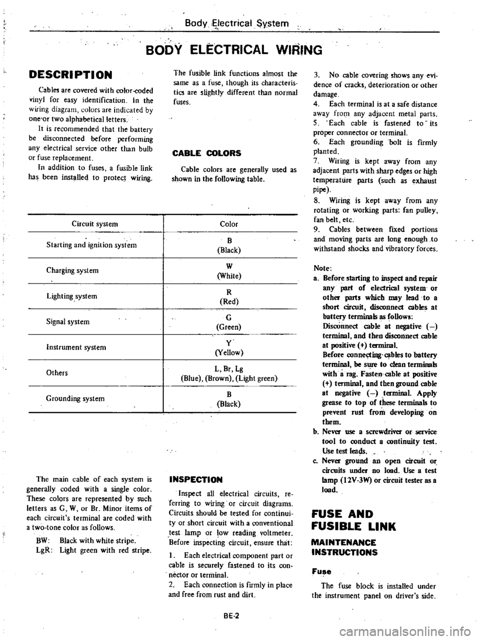
CABLE
COLORS
Cable
colors
are
generally
used
as
shown
in
the
following
table
Color
B
Black
W
White
R
Red
G
Green
y
Yellow
L
Br
Lg
Blue
Brown
Light
green
B
Black
INSPECTION
Inspect
all
electrical
circuits
Ie
Terring
to
wiring
or
circuit
diagrams
Circuits
should
be
tested
for
continui
ty
or
short
circuit
with
a
conventional
test
lamp
or
low
reading
voltmeter
Before
inspecting
circuit
ensure
that
I
Each
electrical
component
part
or
cable
is
securely
fastened
to
its
con
nector
or
tenninal
2
Each
connection
is
fIrmly
in
place
and
free
from
rust
and
dirt
BE
2
3
No
cable
covering
shows
any
evi
dence
of
cracks
deterioration
or
other
damage
4
Each
terminal
is
at
a
safe
distance
3
Vay
from
any
adjacent
metal
parts
5
Each
cable
is
fastened
to
its
proper
connector
or
terminal
6
Each
grounding
bolt
is
fumly
planted
7
Wiring
is
kept
away
from
any
adjacent
parts
with
sharp
edges
or
high
temperature
parts
such
as
exhaust
pipe
8
Wiring
is
kept
away
from
any
rotating
or
working
parts
fan
pulley
fan
belt
etc
9
Cables
between
fIXed
portions
and
moving
parts
are
long
enough
to
withstand
shocks
and
vibratory
forces
Note
a
Before
starting
to
inspect
and
repair
any
part
of
electrical
system
or
oth
parts
which
may
lead
to
a
short
circuit
disconnect
cables
at
battery
terminals
as
follows
Disconnect
cable
at
negative
terminal
and
then
disconnect
cable
at
positive
terminal
Before
connecting
cables
to
battery
terminal
be
s
1
to
clean
tenninals
with
a
rag
Fasten
cable
at
positive
t
minal
and
then
ground
cable
at
negative
tenninal
Apply
grease
to
top
of
these
terminals
to
prevent
rust
from
developing
on
them
b
Ne
use
a
screwdriver
or
service
tool
to
oonduct
a
oontinuity
test
Use
test
leads
Co
Nev
ground
an
open
circuit
or
circuits
under
no
lood
Use
a
test
lamp
I2V
3W
or
circuit
tester
as
a
lood
FUSE
AND
FUSIBLE
LINK
MAINTENANCE
INSTRUCTIONS
Fuse
The
fuse
block
is
installed
under
the
instrument
panel
on
driver
s
side
Page 448 of 548

When
for
one
reason
or
another
fuse
has
melted
use
systematic
proce
dure
to
check
and
eliminate
cause
of
problem
before
installing
new
fuse
Note
a
If
fuse
is
blown
be
sure
to
elimi
nate
cause
of
problem
before
in
stalling
new
fuse
b
Use
fuse
of
specified
rating
Never
use
fuse
of
more
than
specified
rating
c
Check
condition
of
fuse
holders
If
much
rust
or
dirt
is
found
thereon
clean
metal
parts
with
fine
grained
sandpaper
until
proper
metal
to
metal
contact
is
made
Poor
contact
in
any
fuse
holder
will
often
lead
to
voltage
drop
or
heat
ing
in
the
circuit
and
could
result
in
improper
circuit
operation
Body
Electrical
System
W
BE1100
Fig
BE
l
FU
e
Block
Fusible
link
Fusible
link
protects
starting
he
d
lamp
ignition
and
charge
circuits
and
wiring
between
fuse
and
fusible
link
BE1110
Fig
BE
2
Fusible
Link
BE
3
CAUTION
a
If
fusible
link
should
melt
it
is
possible
that
critical
circuit
power
supply
or
large
current
carrying
circuit
is
shorted
In
such
a
case
carefully
check
and
eliminate
cause
of
problem
b
Never
wrap
periphery
of
fusible
link
with
vinyl
tape
Extreme
care
should
be
taken
with
this
link
to
ensure
that
it
does
not
come
into
contact
with
any
other
wiring
har
ness
or
vinyl
or
rubber
parts
A
melted
fusible
link
can
be
detect
ed
either
by
visual
inspection
or
by
feeling
with
finger
tip
If
its
condition
is
questionable
use
circuit
tester
or
test
lamp
as
required
to
conduct
continuity
test
This
continuity
test
can
be
performed
in
the
same
manner
as
for
any
conventional
fuse
Page 449 of 548
Body
Electrical
System
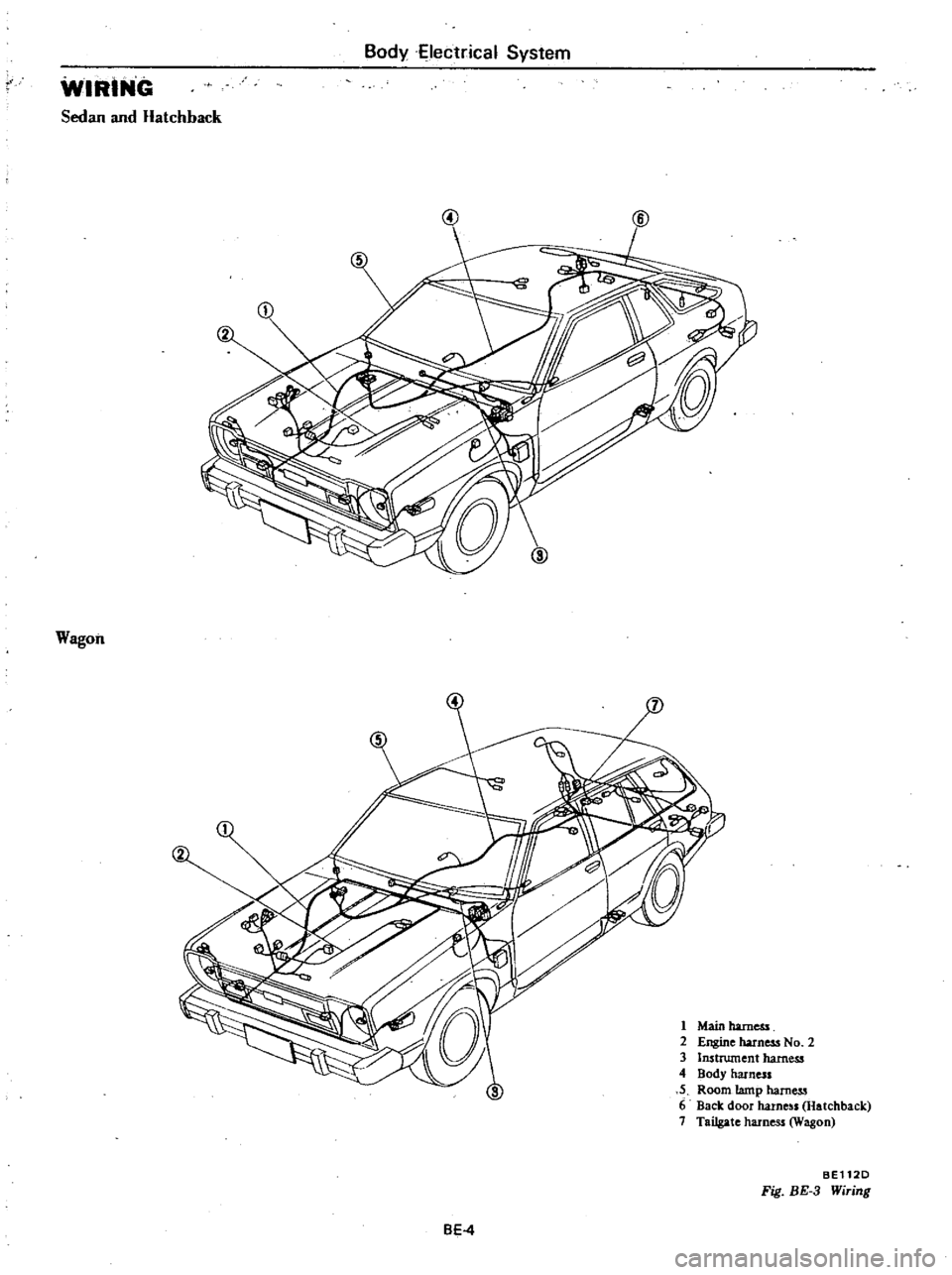
WIRING
Sedan
and
Hatchback
Wagon
2
1
Main
harness
2
Engine
harness
No
2
3
Instrument
harness
4
Body
harness
5
Room
tamp
harness
6
Back
door
harne
ls
Hatchback
7
Tailgate
harness
Wagon
BEl12D
Fig
BE
3
Wiring
BE4
Page 452 of 548
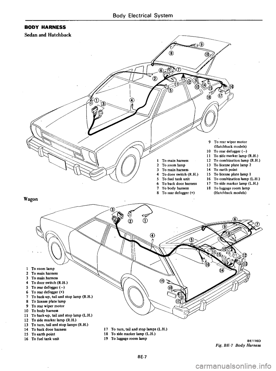
Body
Electrical
System
BODY
HARNESS
Sedan
and
Hatchback
9
To
rear
wiper
motor
Hatchback
models
10
To
rear
defogger
11
To
side
marker
lamp
R
H
12
To
combination
lamp
R
n
13
To
license
plate
lamp
2
14
To
earth
point
15
To
license
plate
lamp
1
16
To
combination
lamp
L
U
17
To
side
marker
lamp
L
H
18
To
luggage
room
lamp
Hatchback
models
Wagon
D
S
3
To
main
hamess
4
To
door
switch
R
n
5
To
rear
defogger
6
To
rear
defogger
7
To
back
up
tail
and
stop
lamp
R
H
8
To
license
plate
lamp
9
To
rear
wiper
motor
10
To
body
harness
11
To
baek
p
tail
and
stop
lamp
L
H
12
To
side
marker
lamp
R
H
13
To
turn
tail
and
stop
lamps
R
n
14
To
back
door
harness
15
To
earth
point
16
To
fuel
tank
unit
@
Yj
qr
@
D
17
To
turn
tail
and
stop
lamps
L
H
18
To
side
marker
lamp
L
U
19
To
luggage
room
lamp
BE116D
Fig
BE
7
Body
Harness
BE
7
Page 453 of 548
BodyElecti
ical
System
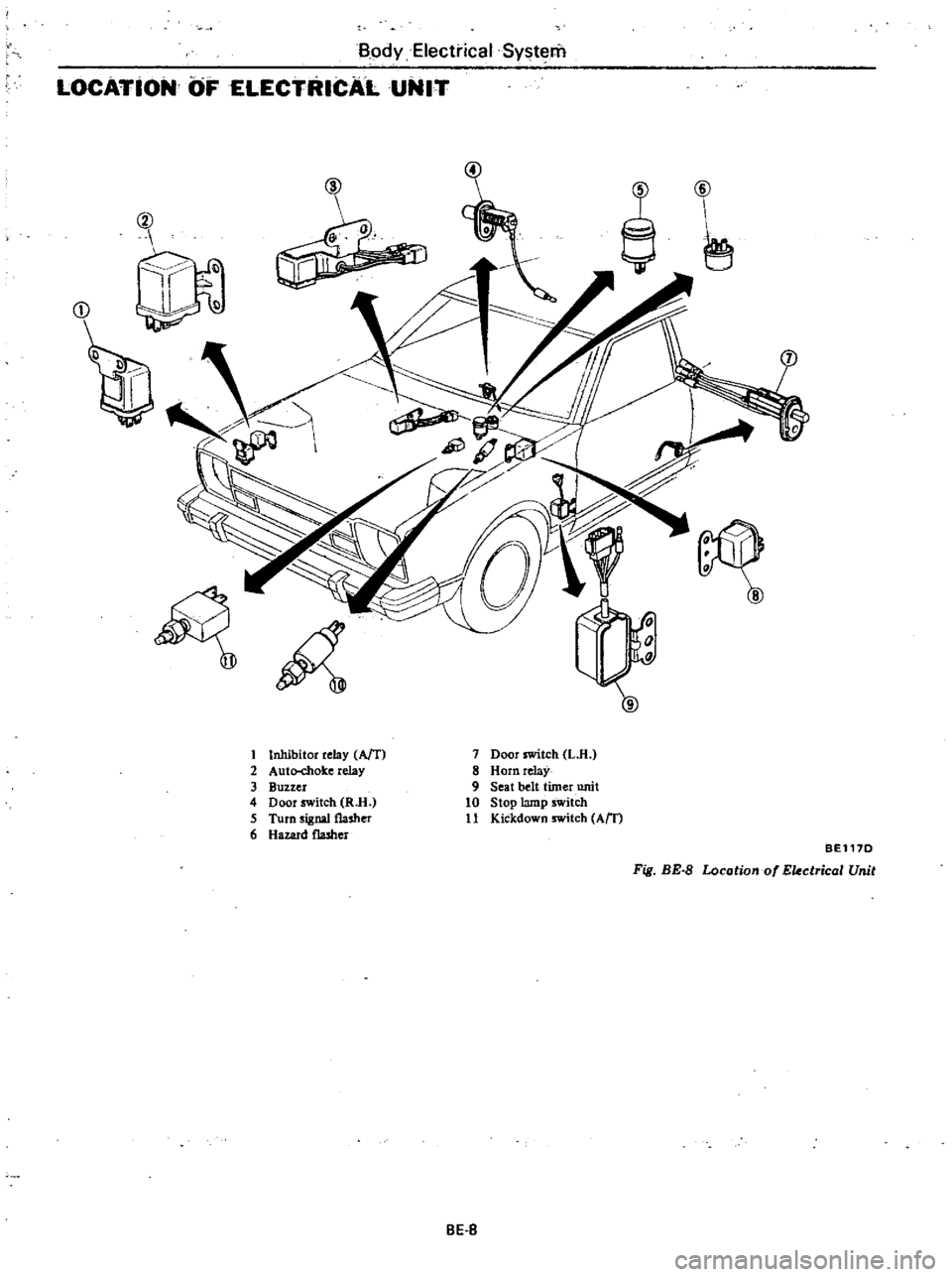
LOCATiON
OF
ELECTRICAL
UNIT
@
Q
J
r
J
D
t
Inhibitor
relay
AfT
2
Auto
chok
e
relay
3
Buzzer
4
Door
switch
RlI
5
Turn
signal
flasher
6
Hazard
flasher
7
Door
switch
L
H
8
Horn
relaY
9
Seat
belt
timer
unit
10
Stop
lamp
switch
11
Kickdown
switch
Am
BEl17D
Fig
BE
8
Locotiono
Ekctricol
Unit
BE
S