ECU DATSUN 210 1979 Repair Manual
[x] Cancel search | Manufacturer: DATSUN, Model Year: 1979, Model line: 210, Model: DATSUN 210 1979Pages: 548, PDF Size: 28.66 MB
Page 279 of 548

Automatic
Transmission
MAJOR
REPAIR
OPERATION
SERVICE
NOTICE
FOR
DISASSEMBLY
AND
ASSEMBLY
I
It
is
advisable
that
repair
opera
tions
be
carried
out
in
a
dust
proof
room
2
Due
to
the
differences
of
the
engine
capacities
the
specifications
of
component
parts
for
each
model
s
transmission
may
be
different
They
do
however
have
common
adjust
ment
and
repair
procedures
as
well
as
cleaning
and
inspection
procedures
outlined
hereinafter
3
During
repair
operations
refer
to
Service
Data
and
Specific3ti
H1s
see
tion
for
the
correct
parts
for
each
model
4
Before
removing
any
of
subas
semblies
thoroughly
clean
the
outside
of
the
transmission
to
prevent
dirt
from
entering
the
mechanical
parts
5
Do
not
use
a
waste
rag
Use
a
nylon
or
paper
cloth
6
After
disassembling
wash
all
dis
assembled
parts
and
examine
them
to
see
if
there
3re
any
worn
damaged
or
defective
parts
and
how
they
are
affected
Refer
to
Service
Data
for
the
extent
of
damage
that
justifies
replacement
7
As
a
rule
packings
seals
and
similar
parts
once
disassembled
should
be
replaced
with
new
ones
TORQUE
CONVERTER
The
torque
converter
is
a
welded
construction
and
can
not
be
disas
sembled
INSPECTION
I
Check
torque
convert
for
any
sign
of
damage
bending
oil
leak
or
deformation
If
necessary
replace
2
Remove
rust
from
pilots
and
bosses
completely
If
torque
converter
oil
is
fouled
or
contaminated
due
to
burnt
clutch
flush
the
torque
converter
as
follows
I
Drain
oil
in
torque
converter
2
Pour
non
lead
gasoline
or
kero
sene
into
torque
converter
approxi
mately
0
5
liter
I
J
V
S
pt
U
Imp
pt
3
Blow
air
into
torque
converter
and
flush
and
drain
out
gasoline
4
Fill
torque
converter
with
torque
converter
oil
approximately
0
5
liter
I
J
V
S
pt
U
Imp
pt
5
Again
blow
air
into
torque
con
verter
and
drain
torque
converter
oil
TRANSMISSION
DISASSEM
LY
I
Drain
oil
from
the
end
of
rear
extension
Mount
transmission
on
Transmission
Case
Stand
ST07g70000
or
ST07860000
Remove
oil
pan
AT118
Fig
A
T
26
R
movin
g
Oil
Pan
2
Remove
bolts
securing
converter
housing
to
transmission
case
Remove
torque
converter
housing
3
Remove
speedometer
pinion
sleeve
bolt
Withdraw
pinion
4
Remove
downshift
solenoid
and
vacuum
diaphragm
Do
not
leave
dia
phragm
rod
at
this
stage
of
dis
assembly
Rod
is
assembled
in
top
of
vacuum
diaphragm
Fig
A
T
27
Dowmhift
Solenoid
and
Vacuum
Diaphragm
AT
27
5
Remove
bolts
which
hold
valve
body
to
transmission
case
Fig
AT
28
Removing
Valve
Body
6
Loosen
lock
nut
CV
on
piston
stem
CD
Then
tighten
piston
stem
in
order
to
prevent
front
clutch
drum
from
falling
when
oil
pump
is
withdrawn
AT121
Fig
AT
29
Loosening
Band
Se11
Jo
7
Pull
out
input
shaft
8
Withdraw
oil
pump
using
Sliding
Hammer
ST25850000
Do
not
allow
front
clutch
to
come
out
of
position
and
drop
onto
floor
AT122
Fig
AT
30
Removing
Oil
Pump
Page 280 of 548

Fig
A
T
31
Removing
Bond
St
t
10
Remove
brake
band
front
clutch
and
rear
clutch
as
an
assembled
unit
II
Remove
connecting
shell
rear
clutch
hub
and
front
planetary
carrier
asa
unit
I
AT12
Fig
AT
32
Removing
Connecting
Shell
12
With
the
aid
of
Snap
Ring
Re
mover
HT69860000
pry
snap
ring
off
output
shaft
fig
A
T
33
Removing
Snap
Ring
13
Remove
connecting
drum
and
inner
gear
of
rear
planetary
carrier
as
an
assembly
Automatic
Transmission
AT126
Fig
A
T
34
Removing
Connecting
D
m
14
Remove
snap
rings
and
then
remove
rear
planetary
carrier
internal
gear
connecting
drum
one
way
clutch
outer
race
nd
one
way
clutch
in
that
order
I
S
Remove
rear
extension
by
loosening
securing
bolts
Fig
A
T
35
Removing
Rear
Extemion
16
Pull
out
output
shaft
remove
oil
distributor
@
together
with
governor
Ive
D
Fig
AT
36
Remov
ngGovernorand
Oil
Di
tributor
17
Pry
off
snap
ring
using
a
pair
of
pliers
Remove
retaining
plate
drive
plate
driven
plate
and
dish
plate
in
that
order
AT
28
Fig
AT
37
Removing
Drive
and
Driven
PltJte
18
Reaching
through
back
side
of
transnlission
case
remove
hex
head
slotted
bolts
To
do
this
use
Hex
head
E
xt
ens
ion
S
T
2
55
7
000
I
ST25570000
One
way
clutch
inner
race
thrust
washer
piston
return
spring
and
thrust
spring
ring
can
now
be
removed
snSS70001
Fig
A
T
38
Removi
Hex
head
Slolted
Boll
19
Blowout
low
and
reverse
brake
piston
by
directing
a
jet
of
air
into
hole
in
cylinder
Fig
A
T
39
Rem
wing
Piolon
20
Remove
band
servo
loosening
allaching
bolts
Page 281 of 548
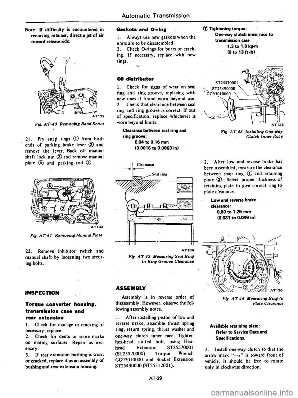
Note
If
difficulty
is
encountered
in
removing
retainer
direct
8
jet
of
air
toward
release
side
Ph
i
AT132
Fig
AT
40
Remov
I
Band
Servo
21
Pry
snap
rings
CD
from
both
ends
of
parking
brake
lever
@
and
remove
the
lever
Back
off
manual
shan
lock
nut
CID
and
remove
manual
plate
@
and
parking
rod
CID
Fig
AT
41
Rtmoving
Manual
Pl4tt
22
Remove
inhibitor
switch
and
manual
shaft
by
loosening
two
secur
ing
bolts
INSPECTION
Torque
converter
houslns
trensmlsslon
use
end
reer
extension
I
Check
for
damage
or
cracking
if
necessary
replace
2
Check
for
dents
or
score
marks
on
mating
surfaces
Repair
as
nee
essary
3
If
rear
extelUlion
bushing
is
worn
or
cracked
replace
it
an
mbly
of
bushing
and
rear
extension
housing
Automatic
Transmission
Geskots
end
Gorin
J
Always
use
new
gaskets
when
the
units
are
to
be
disassembled
2
Check
O
rings
for
burrs
or
crack
ing
If
necessary
replace
with
new
rings
011
distributor
I
Check
for
signs
of
wear
on
seal
ring
and
ring
groove
replacing
with
new
ones
if
found
worn
beyond
use
2
Check
that
clearance
between
seal
ring
and
ring
groove
is
correct
If
out
of
specification
replace
whichever
is
worn
beyond
limits
Clearence
1
n
58el
ring
end
ring
groove
0
04
to
0
16
mm
0
0016
to
0
0063
in
Clearance
Seal
ring
0
o
ii
J
0
1
FI
AT13
Fig
AT
42
Mea
uring
Seal
Ring
to
Ring
Groove
Clearance
ASSEMBLY
Assembly
is
in
reverse
order
of
disassembly
However
observe
the
fol
lowing
assembly
notes
After
installing
piston
of
low
and
reverse
Drake
assemble
thrust
spring
ring
return
spring
thrust
washer
and
one
way
clutch
inner
race
Tighten
hex
head
slotted
bolt
using
Hex
head
Extension
ST2SS7000J
ST2SS70000
Torque
Wrench
GG930JOOOO
and
Socket
Extension
ST2S490000
ST2SSI200J
AT
29
J
Tightening
torque
One
way
clutch
inner
race
to
transminion
case
1
3
to
1
8
kg
m
9
to
13
ft
b
ST25570001
h
ST25490000
GG9
30
10000
Fig
AT
43
1
lalli
ll
One
way
Clutch
Inner
Race
2
After
low
and
reverse
brake
has
been
assembled
measure
the
clearance
between
snap
ring
CD
and
retaining
plate
@
Select
proper
thickness
of
retaining
plate
to
give
correct
ring
to
plate
clearance
Low
and
revene
br
ke
de
r
nce
0
80
to
1
25
mm
0
031
to
0
049
in
Fig
A
T
44
Measuring
Ring
to
Plate
Clearance
Available
retaining
plete
Refer
to
Service
Oeta
and
Specifications
3
Install
one
way
clutch
so
that
the
arrow
mark
4
is
toward
front
of
vehicle
It
should
be
free
to
rotate
only
in
clockwise
direction
Page 282 of 548
ITU
lmQO
d
fJ
AT137
Fig
A
T
45
One
way
Cluleh
4
After
installing
rear
extension
tighten
attaching
bolts
Place
manual
lever
in
P
range
and
check
to
be
sure
that
rear
outpul
shaft
is
securely
blocked
fl
Tightening
torque
Transmission
case
to
rear
extension
2
0
to
2
5
kg
m
14
to
18
fHbl
5
Tighten
servo
retainer
temporari
Iy
at
this
stage
of
assembly
6
Place
rear
clutch
assembly
with
needle
bearing
on
front
assembly
7
Install
rear
clutch
4
lb
and
front
planetary
carrier
AT142
Fig
AT
46
talling
Planetary
Carrier
8
Assemble
connecting
shell
and
other
parts
up
to
front
clutch
in
reverse
order
of
disassembiy
AT143
Fig
AT
47
talling
Canneetin
Shell
Automatic
Transmission
9
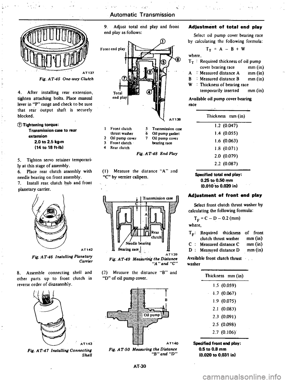
Adjust
total
end
play
and
front
end
playas
follows
Front
end
play
t
Zl
L
r
Total
end
play
AT138
Front
clutch
5
Transmission
ca5e
thrust
washer
6
Oil
pump
gasket
2
OH
pump
cover
7
Oil
pump
cover
3
Front
clutch
bearing
race
4
Rear
clu
tch
Fig
AT
48
End
Play
I
Measure
the
distance
A
and
C
by
vernier
calipers
I
I
Tran
mission
case
t
f
l
1
I
n
0
tic
r
1
A
W
I
I
II
clulch
I
N
ed1e
bearing
Bearing
lace
J
AT139
Fig
A
T
49
MeaSuring
the
Di
tance
A
and
C
2
Measure
the
distance
B
and
D
of
oil
pump
cover
B
AT140
Fig
A
T
50
Measuring
the
Di
tance
cB
and
n
AT
30
Adjustment
of
totel
end
pley
Select
oil
pump
cover
bearing
race
by
calculating
thc
following
formula
TT
A
B
W
where
T
T
Required
thickness
of
oD
pump
cover
bearing
race
mm
in
A
Measured
distance
A
mm
in
B
Measured
distance
B
mm
in
W
Thickness
of
bearing
race
temporarily
inserted
mm
in
A
vaDable
oil
pump
cover
bearing
race
Thickness
nun
in
1
2
0
047
I
4
0
055
1
6
0
063
1
8
0
071
2
0
0
079
2
2
0
Og7
Specified
totel
end
play
0
25
to
0
50
mm
o
oio
to
0
020
inl
Adjustment
of
front
end
pley
Select
front
clutch
thrust
washer
by
calculating
the
following
formula
T
F
C
D
0
2
mm
where
T
F
Required
thickness
clutch
thrust
washer
C
Measured
distance
C
D
Measu
red
distance
D
Available
front
clutch
thrust
washer
of
front
mm
in
nun
in
mm
in
Thickness
mm
in
1
5
0
059
I
7
0
067
1
9
0
075
2
1
0
083
2
3
0
091
2
5
0
098
2
7
0
106
Specified
front
end
pley
0
5
to
0
8
mm
0
020
to
0
031
inl
Page 283 of 548
Note
L
C
llTect
thid
ness
of
bearing
race
end
thrust
washer
is
always
the
one
which
is
nearest
the
calculated
one
b
InsteJled
thid
noss
of
oil
pump
gasket
is
0
4
mm
0
016
in
10
Check
to
b
sure
that
brake
servo
piston
moves
freely
For
detailed
procedure
refer
to
page
AT
33
for
Servo
Piston
Use
care
to
prevent
piston
from
coming
out
of
place
dur
ing
testing
since
servo
retainer
is
not
tightened
at
this
point
of
assembly
II
Make
sure
that
brake
band
strut
is
correctly
installed
Tighten
piston
stem
Back
off
two
full
turns
end
secure
with
lock
nul
l
l
Tightening
torqUl
Piston
stem
1
2
to
1
5
kg
m
9
to
11
ft
lbl
Piston
tem
lock
nut
1
5
to
4
0
kg
m
11
to
29
ft
lbl
Available
diaphragm
rod
Distance
measured
L
mm
in
Under
25
55
1
0059
25
65
to
26
05
1
0098
to
1
0256
26
15
to
26
55
1
0295
to
1
0453
26
65
to
27
05
1
0492
to
1
0650
Over
27
15
1
0689
COMPONENT
PARTS
The
transmission
consists
of
many
all
parts
that
are
quite
alike
in
oonstruction
yet
machined
to
very
close
tolerances
When
disassembling
parts
be
sure
to
place
them
in
order
in
part
rack
so
they
can
be
restored
in
the
unit
in
their
proper
positions
It
is
also
very
important
to
perform
func
lional
test
whenever
it
is
designated
Automatic
Transmission
12
After
inhibitor
switch
is
in
stalled
check
to
be
sure
that
it
op
erates
properly
in
each
range
For
detailed
procedure
refer
to
page
AT
40
for
Checking
and
Adjusting
lnhibi
tor
Switch
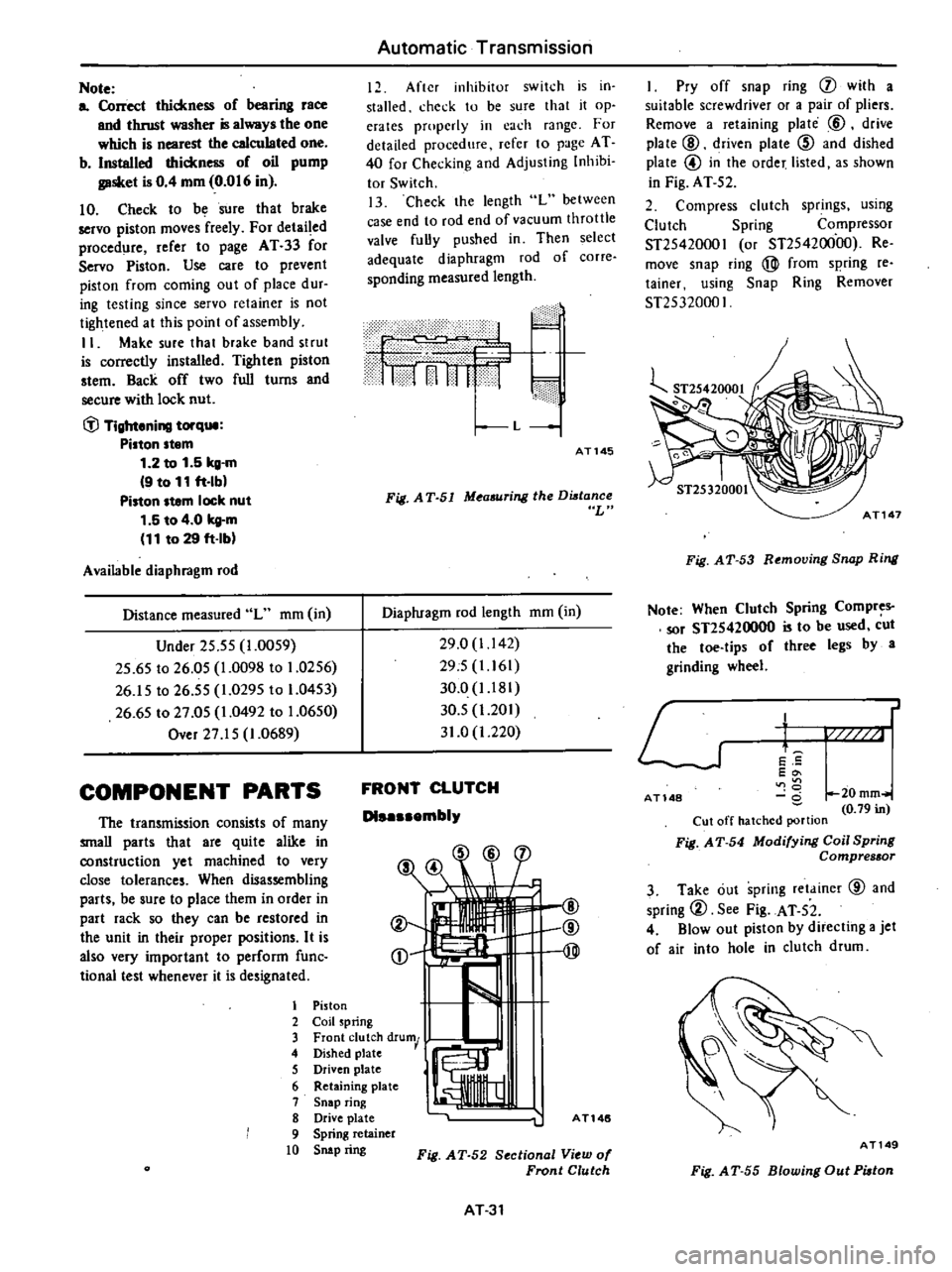
13
Check
the
length
L
between
case
end
to
rod
end
of
vacuum
throttle
valve
fully
pushed
in
Then
select
adequate
diaphragm
rod
of
corre
sponding
measured
length
1
11f1
n
1
11
1
1
f
c
dllidf
i
L
AT145
Fig
A
T
51
M
asuring
the
Dutance
L
Diaphragm
rod
length
mm
in
29
0
1
142
295
1
161
30
0
I
181
30
5
1
201
31
0
1
220
FRONT
CLUTCH
Dl
mbly
@
@
@
I
Piston
2
Coil
spring
3
Front
clutch
drum
4
Dished
plate
5
Driven
plate
I
6
R
I
etammg
plate
7
Snap
ring
8
Drive
plate
A
T146
9
Spring
retainer
10
Snip
ring
Fig
AT
52
Section
1
View
of
Fronl
Clulch
AT31
I
Pry
off
snap
ring
j
with
a
suitable
screwdriver
or
a
pair
of
pliers
Remove
a
retaining
plate
@
drive
plate
@
driven
plate
@
and
dished
plate
@
in
the
order
listed
as
shown
in
Fig
AT
52
2
Compress
clutch
springs
using
Clutch
Spring
Compressor
ST25420001
or
ST25420000
Re
move
snap
ring
@
from
spring
reo
tainer
using
Snap
Ring
Remover
ST25320001
Fig
AT
53
Removing
Snap
Ring
Note
When
Clutch
Spring
Compres
sor
ST2S420000
is
to
be
used
cut
the
toe
tips
of
three
legs
by
a
grinding
wheel
L
J
t
E
5
Eo
U
0
20mm
0
79
in
Cut
off
hatched
portion
Fig
A
T
54
Modifying
Coil
Spring
Compressor
AT
148
3
Take
out
spring
retainer
@
and
spring
2
See
Fig
AT
52
4
Blowout
piston
by
directing
a
jet
of
air
into
hole
in
clutch
drum
AT149
Fig
A
T
55
Blowing
Out
Piolon
Page 285 of 548
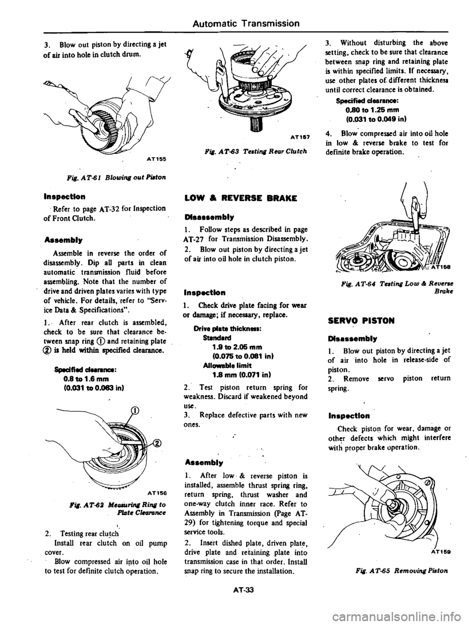
3
Blowout
piston
by
directing
a
jet
of
air
into
hole
in
clutch
drum
AT155
Fig
AT
61
Blowing
out
PWton
In
pectlon
Refer
to
page
AT
32
for
Inspection
of
Front
Clutch
As
mbly
Assemble
in
reverse
the
order
of
disassembly
Dip
all
parts
in
clean
automatic
transmission
fluid
before
assembling
Note
that
the
number
of
drive
and
driven
plates
varies
with
type
of
vehicle
For
details
refer
to
Serv
ice
Data
Specifications
I
After
rear
clutch
is
assembled
check
to
be
sure
that
clearance
be
tween
snap
ring
Q
and
retaining
plate
@
is
held
within
specified
clearance
Speelfied
d
0
8
to
1
6
mm
0
031
to
0
083
inl
AT156
Fig
AT
62
Meaiuring
Ring
to
Plate
C
canInce
2
Testing
rear
c1u
ch
Install
rear
clutch
on
oil
pump
cover
Blow
compressed
air
i
1to
oil
hole
to
test
for
definite
clutch
operation
Automatic
Transmission
II
AT1
7
Fill
A
T
63
Te
ting
Rear
Clutch
LOW
REVERSE
BRAKE
D1
mbly
I
Follow
steps
as
described
in
page
AT
27
for
Transmission
Disassembly
2
Blowout
piston
by
directing
a
jet
of
air
into
oil
hole
in
clutch
piston
In
pectlon
1
Check
drive
plate
facing
for
wear
or
demege
if
necesaary
replace
Drive
plate
thielm
Standard
1
9
to
2
05
mm
0
075
to
0
081
in
Allowable
limit
1
8
mm
0
071
inl
2
Test
piston
return
spring
for
weakness
Discard
if
weakened
beyond
use
3
Replace
defective
parts
with
new
ones
As
mbly
I
After
low
reverse
piston
is
installed
assemble
thrust
spring
ring
return
spring
thrust
washer
and
one
way
clutch
inner
race
Refer
to
Assembly
in
Transmission
page
AT
29
for
tightening
torque
and
special
service
tools
2
Insert
dished
plate
driven
plate
drive
plate
and
reiaining
plate
into
transmission
case
in
that
order
Install
snap
ring
to
secure
the
installation
AT
33
3
Without
disturbing
the
above
setting
check
to
be
sure
that
clearance
between
snap
ring
and
retaining
plate
is
within
specified
limits
If
nece
ry
use
other
plates
of
different
thickness
until
correct
clearance
is
obtained
Specified
deereM8
0
80
to
1
25
mm
0
031
to
0
049
inl
4
Blow
compressed
air
into
oil
hole
in
low
roverse
brake
to
test
for
deftnite
brake
operation
Fill
AT
64
Tuting
Low
Reverse
Broke
SERVO
PISTON
D1
mbly
I
Blowout
piston
by
dilecting
a
jet
of
air
into
hole
in
release
side
of
piston
2
Remove
servo
piston
return
spring
In
p
ctlon
Check
piston
for
wear
damage
or
other
defects
which
might
interfere
with
proper
brake
opcration
Fig
AT
65
Removing
Piaton
Page 287 of 548

Fig
AT
70
MeG6Uring
Clearonce
Clearance
between
seal
ring
and
ring
groove
Stendard
0
04
to
0
16
mm
10
002
to
0
006
in
I
31earance
Seal
ring
w
I
J
7
r
11
AT1
5
II
Fig
AT
71
MeG6Uring
Clearance
As
mblr
L
Set
up
pump
housing
with
inner
and
outer
pump
gears
on
it
2
Using
Oil
Pump
Assembling
Gauge
ST2SS80001
instan
pump
cover
to
pump
houaing
AT166
Fig
AT
72
Centering
Oil
Pump
3
Temporarily
tighten
pump
secur
ing
bolts
4
Set
the
cunout
of
oil
pump
cover
within
specified
total
indicator
read
ing
Automatic
Transmission
Total
indicator
reading
Lell
than
0
07
mm
10
0028
inl
ST2SSBOOOl
AT264
Fig
AT
73
Me
ring
Runout
S
Tighten
pump
securing
bolts
to
specified
torque
r
Tightening
torque
Oil
pump
housing
to
oil
pump
cover
0
6
to
0
8
kg
m
14
3
to
5
8
ft
Ibl
Note
Be
sure
to
align
con
ter
housini
securing
bolt
holes
6
Again
check
the
runout
of
oil
pump
cover
Note
When
former
Oil
Pump
As
sembling
Gauge
is
to
be
used
make
a
screw
hole
in
side
of
it
PLANETARY
CARRIER
The
planetary
carrier
cannot
be
divided
into
its
individual
components
If
any
part
of
component
is
defec
tive
replace
the
carrier
as
a
unit
In
p
ctlon
Check
clearance
between
pinion
washer
and
planetary
carrier
with
a
feeler
Standard
d
0
20
to
0
70
mm
0
008
to
0
028
in
AT
35
uan
r
J
II
I
AT1S7
Fig
AT
74
MeG6Uring
Pinion
Waaher
to
CanUr
Clearance
Replace
if
over
0
80
mm
0
031
in
CONTROL
VALVE
Tlte
control
valve
assembly
consists
of
many
precision
parts
and
requires
extreme
care
when
it
has
to
be
re
moved
and
serviced
It
is
good
practice
to
place
parts
in
a
part
rack
so
that
they
can
be
reassembled
in
valve
body
in
their
proper
positions
Added
care
should
also
be
exercised
to
prevent
springs
and
other
small
parts
from
being
sca
ttered
and
lost
Before
assembly
dip
all
parts
in
clean
automatic
transmission
fluid
and
check
to
be
certain
that
they
are
free
of
lint
and
other
minute
particles
If
clutch
or
band
is
burnt
or
if
oil
becomes
fouled
the
control
valve
as
sembly
should
be
disassembled
and
flushed
DI
mblr
I
Remove
bolts
and
nuts
which
retain
oil
strainer
Bolts
may
be
re
moved
with
a
screwdriver
but
it
is
recommended
that
Hexagon
Wrench
lIT61000S00
and
Spinner
Handle
lIT623S0000
b
used
Page 293 of 548
with
the
pin
hole
of
the
internal
rotor
combined
with
the
manual
shaft
and
check
their
alignment
by
inserting
a
1
5
mm
0
059
in
diameter
pin
into
the
holes
If
the
alignment
is
correct
fasten
the
switch
body
with
the
bolts
pull
out
the
pin
tighten
up
the
screw
in
the
hole
and
fasten
the
selector
lever
as
before
Check
the
continuity
pin
with
the
lesler
If
Ihe
malfunc
tion
still
remains
replace
the
inhibitor
switch
STALL
TEST
The
purpose
of
this
test
is
to
check
the
transmission
and
engine
for
trou
ble
by
measuring
the
maximum
num
bers
of
revoiutions
o
the
cngine
while
vehicle
is
held
in
a
stalled
condition
The
carburetor
is
in
fullthrollle
opera
tion
with
the
selector
lever
in
ranges
1
2
and
I
respectively
Com
pale
the
measured
results
with
the
standard
values
Components
to
be
tested
and
test
itelJUl
I
Clutches
brake
and
band
in
trans
mission
for
slipping
2
Torque
converter
for
proper
func
tioning
3
Engine
for
overall
properly
STAU
TEST
PROCEDURES
Before
testing
check
the
engine
oil
and
torque
converter
oil
warm
up
the
engine
cooling
w
ter
to
suitable
tem
perature
by
running
at
1
200
rpm
with
the
selector
lever
in
the
range
P
for
sevcral
minutes
Warm
up
the
torque
converter
oil
to
suitable
temperature
60
to
lOOoC
140
to
2120F
I
Mount
the
engine
tachometer
at
a
location
that
allows
good
visibility
from
the
driver
s
seat
and
put
a
mark
on
specified
revolutions
on
the
meter
2
Secure
the
front
and
rear
wheels
with
chocks
and
apply
the
hand
brake
Be
SIIre
to
depress
the
brake
pedal
firmly
with
the
left
foot
before
de
pressing
the
accelerator
pedal
3
Throw
the
selector
lever
into
the
range
11
4
Slowly
depress
the
accelerator
pedal
until
the
throttle
valvc
is
fully
Automatic
Transmission
opened
Quickly
read
and
record
the
engine
revolution
when
the
engine
begins
to
rotate
steadily
and
then
release
the
accelerator
pedal
5
Shift
the
selector
lever
to
N
and
operate
the
engine
at
approxi
mately
1
200
rpm
for
more
than
one
minute
to
cool
down
the
torque
con
verter
oil
and
coolant
6
Make
similar
staU
tests
in
ranges
2
I
and
R
CAUTION
The
dill
test
operstion
81
specified
in
i18m
4
should
be
I118de
within
fiv
lIeonds
If
it
tBkes
too
long
the
oil
If
and
the
cluti
hn
blllke
and
b
nd
elll
ly
I
Suf
ficient
cooling
time
should
be
given
r
eech
test
for
the
four
IlInges
0
Z
1
end
R
JUDGEMENT
High
stall
revolution
more
than
staitdard
revolution
If
the
engine
levolulion
in
stall
condi
ion
is
higher
than
the
standard
values
it
indicates
that
onc
or
more
clutches
in
the
transmission
are
slipping
and
therefore
no
further
test
is
required
For
the
following
abnormalities
the
respective
causes
are
presumed
High
rpm
in
all
ranges
low
line
pr
ssure
High
rpm
in
0
2
and
I
and
normal
rpm
in
6R
Rear
clutch
slipping
High
rpm
in
D
and
2
and
normal
rpm
in
One
way
clutch
slipping
High
Ipm
in
R
only
Front
clutch
or
low
and
reverse
brake
slipping
To
determine
which
is
slipping
front
clutch
or
low
and
reverse
brake
a
road
test
is
needed
If
while
coasting
after
starting
with
the
levcr
in
I
range
engine
braking
does
not
work
properly
the
low
and
reverse
brake
is
slipping
Otherwise
the
front
clutch
is
slipping
Slipping
of
the
band
brake
is
diffi
cuJt
to
ascertain
However
jf
it
occurs
with
the
lever
in
1
range
engine
AT
41
revolution
increases
up
to
the
same
level
as
in
1st
range
It
is
impossible
to
check
it
in
the
stall
test
2
Standard
stall
rnoluiion
If
the
engine
revoluiion
in
stall
ondition
is
within
he
standard
values
the
control
elements
are
nOf
mally
operating
in
the
ranges
D
2n
I
and
R
Also
the
engine
and
one
way
clutch
of
the
torque
converter
are
norinal
in
performance
and
operation
The
one
way
clutch
of
the
torque
converter
however
sometimes
sticks
This
is
determined
in
the
road
test
3
Lower
stall
revolution
than
lIand
ard
revolution
If
the
engine
revolution
in
stall
condition
is
lower
than
the
standard
values
it
indicates
that
the
engine
is
in
abnormal
condition
or
the
torque
con
verter
s
one
way
clutch
is
slipping
4
O
hers
I
If
the
accelerating
performance
is
poor
until
vehicle
speed
of
approxi
mately
SO
kmfh
30
MPH
is
attained
and
then
normal
beyond
that
speed
it
can
be
judged
that
the
torque
con
verte
c
s
one
way
clutch
is
slipping
2
If
the
torque
converter
sane
way
dutch
sticks
vehicle
speed
can
not
exceed
approximately
80
kmfh
SO
MPH
in
the
road
tesl
In
such
a
case
the
torque
converter
oil
tem
perature
rises
abnormally
and
so
special
care
is
required
3
If
the
transmission
does
not
op
erate
properly
at
all
vehicle
speeds
it
indicates
poor
engine
performance
ROAD
TEST
An
accurate
knowledge
of
the
au
to
matic
transmission
is
required
for
an
exact
diagnosis
II
is
recommended
that
a
diagnosis
guide
chart
with
the
standard
vehicle
speeds
for
each
stage
of
the
up
and
down
shiftings
be
prepared
Measured
vehicle
speeds
are
to
be
filled
in
the
adjoining
column
after
each
testing
Also
it
is
advisable
to
mount
a
stopper
for
positioning
the
throttle
opening
Page 296 of 548

LlNE
PRESSURE
TEST
When
any
slipping
occurs
in
clutch
or
brake
or
the
feeling
during
a
speed
change
is
not
correct
the
line
pressure
must
be
checked
Measuring
line
pressure
is
done
by
a
pressure
gatqle
attached
to
pressure
measuring
holea
after
removing
blind
pluga
locate
d
at
transmission
case
The
line
pressure
measurement
is
begun
at
idling
and
taken
step
by
step
by
enlarging
the
throttle
opening
Automatic
Transmission
For
line
pressure
data
when
shift
ing
gem
refer
to
Road
Test
1
A
sharp
shock
in
up
shifting
or
too
high
changing
speeds
are
caused
mostly
by
too
high
throttle
pressure
2
Slipping
or
incaPability
of
opera
tion
is
mostly
due
to
oil
pressure
leakage
within
the
gear
trains
or
spool
valve
LINE
PRESSURE
GOVERNOR
FEED
PRESSURE
Non
Cellfornill
models
Seden
and
Halchbeck
At
idling
Range
At
stall
test
R
Une
pressure
kg
em
psi
Range
3
0
to
5
5
43
to
7S
3
0
to
4
0
43
to
57
6
0
to
12
0
S5to
171
o
2
R
D
3
0
to
4
0
43
to
57
2
snSOSSOOI
CD
AT454
1
Line
pressure
2
Governorpressure
3
Servo
release
prenure
Fig
AT
87
Mecuuring
Line
Pre
Line
pressure
kg
cm2
psi
14
0
to
16
0
199
to
22S
94
to
11
0
134
to
156
10
0
to
12
0
142
to
171
94
to
11
0
134
to
156
At
idling
California
models
All
models
end
Non
Callfornill
modela
Wa
on
At
stall
test
R
Line
pressure
kg
cm
psi
Range
Range
R
o
4
2
to
5
6
60
to
SO
3
2
to
3
S
46
to
54
D
2
6
0
to
II
7
S5
to
166
2
3
2
to
3
S
46
to
54
AT44
Une
pressure
kg
cm2
psi
143
to
16
2
203
to
230
9
9
to
11
1
141
to
15S
10
2
to
II
7
145
to
166
9
9
to
11
1
14110
15S
Page 309 of 548
Propeller
Shaft
Differential
Carrier
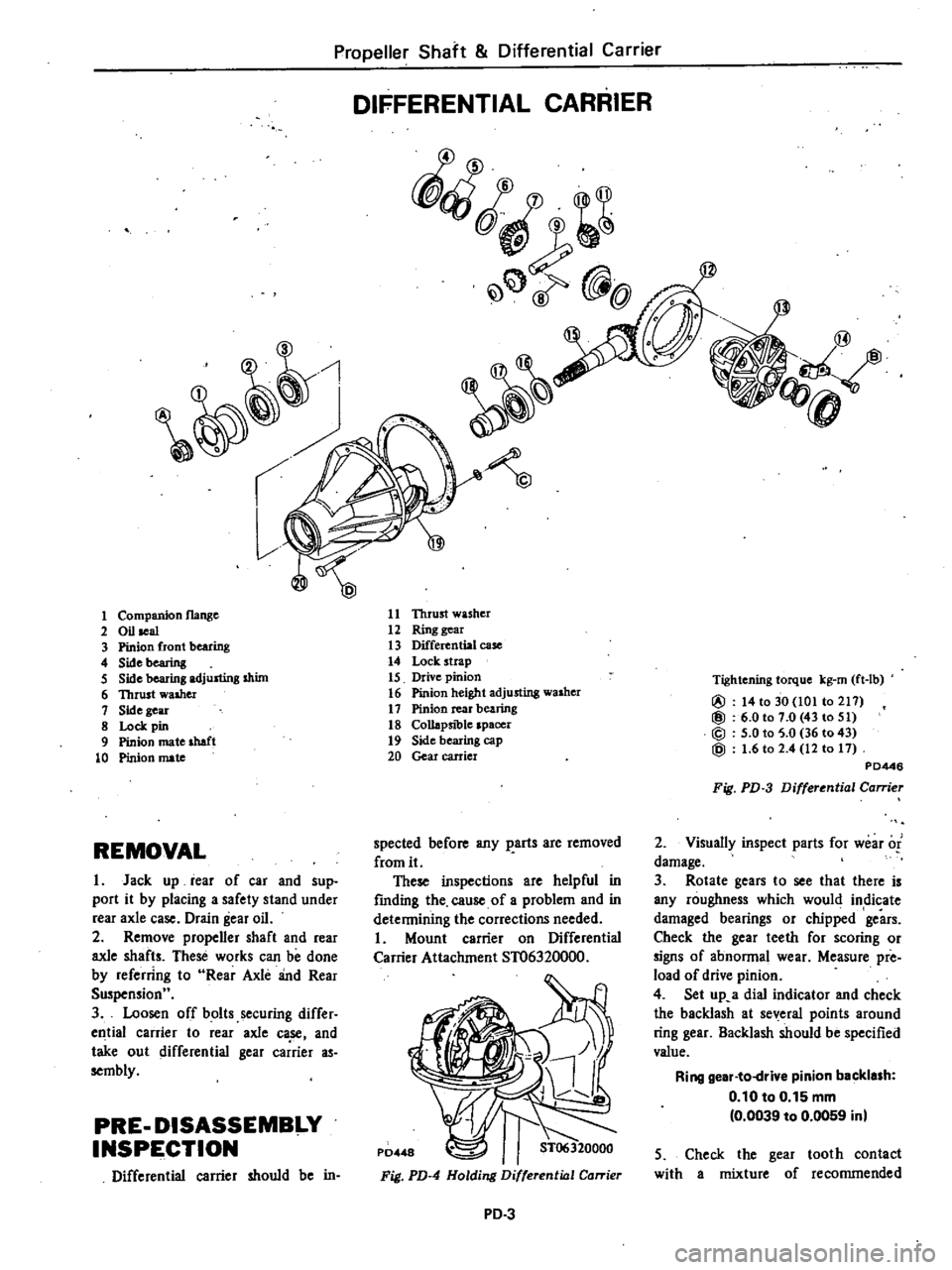
DIFFERENTIAL
CARRIER
fQ
@
1
11
Thrust
washer
12
Ring
gear
13
Differential
case
14
Lock
strap
15
Drive
pinion
16
Pinion
height
adjusting
washer
17
Pinion
rear
bearing
18
Collapsible
spacer
19
Side
bearing
cap
20
Gear
carrier
1
Companion
flange
2
Oil
seal
3
Pinion
front
bearing
4
Sidebearing
5
Side
bearing
adjusting
shim
6
Thrust
walher
1
Side
gear
8
Lock
pin
9
Pinion
mate
shaft
10
Pinion
mate
Tightening
torque
kg
rn
ft
lb
@
14
to
30
101
to
211
@
6
0101
0
43
to
51
@
5
0
to
5
0
36
to
43
@
1
6
to
2
4
12
to
11
PD446
Fig
PD
3
Differential
Carrier
2
Visuany
inspect
parts
for
wear
of
damage
3
Rotate
gears
to
see
that
there
is
any
roughness
which
would
indicate
damaged
bearings
or
chipped
gears
Check
the
gear
teeth
for
scoring
or
signs
of
abnonnal
wear
Measure
pre
load
of
drive
pinion
4
Set
up
a
dial
indicator
and
check
the
backlash
at
several
points
around
ring
gear
Backlash
should
be
specified
value
Ring
gear
to
drive
pinion
backlash
0
10
to
0
15
mm
0
0039
to
0
0059
inl
spected
before
any
parts
are
removed
from
it
These
inspections
are
helpful
in
fmding
the
cause
of
a
problem
and
in
detennining
the
corrections
needed
Mount
carrier
on
Differential
Carrier
Attachment
ST06320000
REMOVAL
I
Jack
up
rear
of
car
and
sup
port
it
by
placing
a
safety
stand
under
rear
axle
case
Drain
gear
oil
2
Remove
propener
shaft
and
rear
axle
shafts
These
works
can
be
done
by
referring
to
Rear
Axle
and
Rear
Suspensionu
3
Loosen
off
bolts
securing
differ
ell
tial
carrier
to
rear
axle
ca
se
and
take
out
differential
gear
carrier
as
sembly
PRE
DISASSEMBI
Y
INSPE
CTION
Differential
carrier
should
be
in
5
Check
the
gear
tooth
contact
with
a
mixture
of
recommended
Fig
PD
4
Holding
Differential
Carrier
PD
3