wheel DATSUN 210 1979 Manual PDF
[x] Cancel search | Manufacturer: DATSUN, Model Year: 1979, Model line: 210, Model: DATSUN 210 1979Pages: 548, PDF Size: 28.66 MB
Page 398 of 548
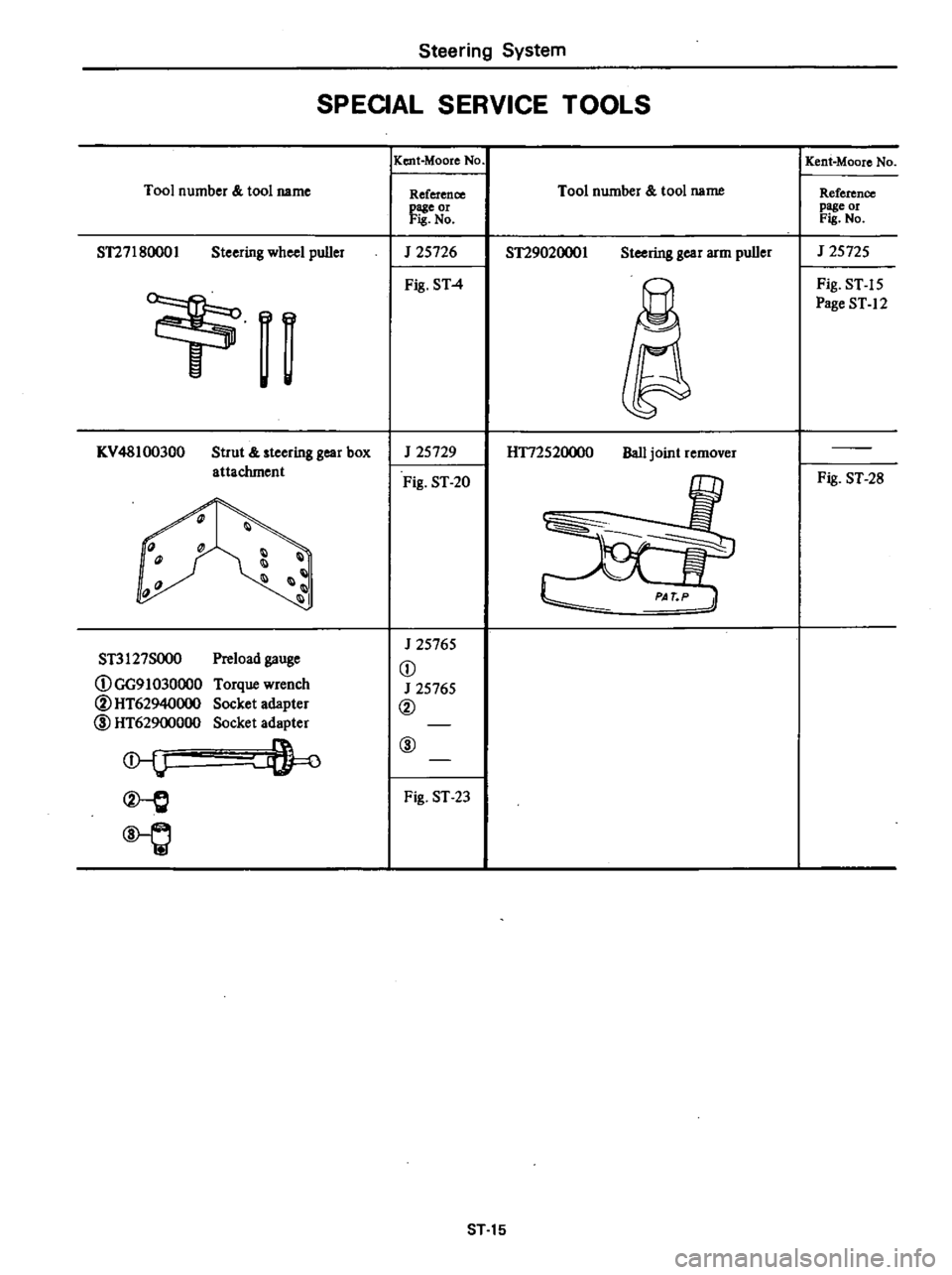
Steering
System
SPEOAL
SERVICE
TOOLS
Tool
number
tool
name
ST27180001
Steering
wheel
puller
n
I
KV
48100300
Strut
steering
gear
box
attachment
1l
1
III
11
Preload
gauge
Torque
wrench
Socket
adapter
Socket
adapter
ST3127SOO0
DGG91030000
@HT62940000
l
HT62900000
l
Q
IKent
Moore
No
Reference
page
or
Fis
No
J
25726
Fig
ST
4
J
25729
Fig
ST
20
J
25765
D
J
25765
@
@
Fig
ST
23
Tool
number
tool
name
ST29020001
Steering
gear
arm
puller
H172520000
Ball
joint
remover
ST
15
Kent
Moore
No
Reference
page
or
Fis
No
J
25725
Fig
ST
15
Page
ST
12
Fig
ST
28
Page 419 of 548

Body
2
Length
of
shock
absorber
Front
shock
absorber
I
164
6
46
q
j
0
I
0
0
67
2
64
Rear
shock
absorber
G
riA
l
yll
L
J
J
Unit
mm
in
3
Checking
shock
absorber
I
Place
car
in
front
of
a
wall
Apply
hand
brake
and
place
wheel
chocks
securely
2
Place
a
jack
between
wall
and
extend
jack
approximately
20
mm
0
79
in
The
bumper
should
move
approxilnately
50
mm
I
97
in
back
ward
through
shock
absorber
opera
tion
See
Fig
BF
IO
Note
Use
a
jack
with
y
of
more
than
600
kg
I
3231b
94
3
70
rL
I
i
r
T
l
f
L
W
67
2
64
1
8F742B
Fig
BF
9
Length
of
Shock
Absorber
3
Make
sure
bumper
returns
to
its
original
position
when
jack
is
re
tracted
Note
When
replacing
shock
absorb
ers
make
Sure
they
are
of
the
same
type
and
rating
and
manufactured
by
the
same
maker
4
For
rear
bumper
utilize
the
same
procedures
as
described
for
front
bumper
f
BF7438
1
Front
bumper
2
Jack
3
Wheel
chock
Fig
BF
10
Checking
Shock
Abaorber
Function
BF
8
FRONT
BUMPER
REMOVAL
AND
INSTALLATION
1
Loosen
bolts
attaching
front
bumper
to
shock
absorbers
and
re
move
bumper
See
Fig
BF
5
2
Loosen
bolts
attaching
shock
ab
sorbers
to
radia
tor
core
support
and
side
members
and
remove
shock
absorbers
3
Install
shock
absorbers
and
front
bumper
in
reverse
order
of
removal
and
adjust
bumper
height
as
shown
in
Fig
BF
7
fj
Tightening
torque
Front
bumper
Bumper
to
shock
absorber
attaching
bolt
6
0
to
8
0
kg
m
43
to
58
ft
Ib
Shock
absorber
to
body
attaching
bolt
and
nut
front
0
93
to
1
2
kg
m
6
7
to
B
7
ft
Ibl
attaching
bolt
and
nut
sida
1
9
to
2
5
kg
m
14
to
18
ft
b
REAR
BUMPER
REMOVAL
AND
INSTALLATION
1
Loosen
bolts
attaching
rear
bumper
to
shock
absorbers
and
re
move
rear
bumper
See
Fig
BF
6
2
Loosen
bolts
and
nuts
attaching
shock
absorbers
to
side
members
and
remove
shock
absorbers
3
Install
shock
absorbers
an
rear
bumper
in
reverse
order
of
removal
and
adjust
rear
bumper
height
as
shown
in
Fig
BF
B
fj
Tightening
torque
Rear
bumper
Bumper
to
shock
absorber
attaching
bolt
rear
6
0
to
8
0
kg
m
43
to
58
ft
b
Shock
absorber
to
body
attaching
bolt
and
nut
rear
0
93
to
1
2
kg
m
6
7
to
8
7
ft
b
attaching
bolt
and
nut
side
6
0
to
BoO
kg
m
43
to
58
ft
b
Page 444 of 548

Body
f
9
Fig
BF
98
side
finisher
5
Rear
t
back
fini
her
6
Rear
sea
late
7
Front
kickmg
p
k
king
plate
8
Rear
Ie
d
rear
molding
9
Drip
cente
o
r
garnish
10
Rear
Sld
r
molding
11
Front
p
Iding
fender
mo
12
Rear
BF784B
d
Molding
2
Door
Body
Sid
Trim
an
h
side
finisher
1
Das
h
llargarms
2
Front
pi
de
welt
3
Body
front
51
h
ilIargamls
4
Center
p
HATCHBACK
50
5
1
Dash
side
finishe
h
ilJargarms
2
Front
p
de
welt
3
Body
I
4
5
6
7
8
9
Luggage
rear
finis
er
10
liar
moldmg
11
Fropt
p
r
molding
12
Drip
cent
d
er
garnish
13
Lyggage
f1
or
boar
Rear
covslde
finisher
de
ollar
cover
Luggage
14
Lo
pi
Iding
are
wheel
cover
15
Rear
fender
o
ontkICkill8
plate
16
Air
out1etgrd
molding
k
g
plate
rtel
WlD
Rear
klc
In
17
Qua
8F7878
d
Imlsher
Rear
SI
e
nd
Molding
Side
Trim
a
Fig
BF
99
Body
BF
33
Page 455 of 548
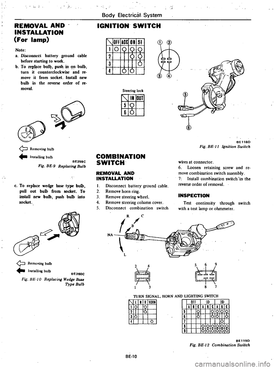
REMOVAL
AND
INSTALLATION
For
lamp
Note
a
Disconnect
battery
ground
cable
before
starting
to
work
b
To
repJaoe
bull
push
ill
n
bulb
turn
it
counterclockwise
and
re
move
it
from
socket
Install
new
bulb
in
tbe
reverse
order
of
re
moval
9
Removing
bulb
Installing
bulb
BE259C
Fig
BE
9
Replacing
Bulb
c
To
repbce
wedge
base
type
bulb
puD
out
bulb
from
socket
To
inslaD
new
bulb
pusb
bulb
into
socket
Removing
bulb
Installing
bulb
Fig
BE
10
BE260C
R
eplac
ing
Wedge
BlUe
Type
Bulb
Body
Electrical
System
IGNITION
SWITCH
OFF
ICC
01
ST
I
0
0
61
1
ot
Steering
lock
5
I
OUT
I
Iso
16
6
I
T
BEll8D
Fig
BE
II
Ignition
Switch
COMBINATION
SWITCH
wires
at
connector
6
Loosen
retaining
screw
and
Ie
move
combination
switch
assembly
7
lnstaD
combination
switch
in
the
reverse
order
of
removal
REMOVAL
AND
INSTALLATION
I
Disconnect
battery
ground
cable
2
Remove
horn
ring
3
Remove
steering
wheel
4
Remove
steering
column
cover
5
Disconnect
combination
switch
INSPECTION
Test
continuity
through
switch
with
a
test
lamp
or
ohmmeter
TURN
SIGNAL
HORN
AND
LIGHTING
SWITCH
1
1
R
HORMI
119
0
I
12
I
6
I
136
I
II
0
I
III
I
F
c
I
c
I
c
15
0
QQOQ
16
6
56
I
5
11
0
II
000Q
10
9
000000
BE119D
Fig
BE
12
Combination
Switch
BE
l0
Page 458 of 548
Body
Electrical
System
INSPECTION
4
Installation
is
in
the
reverse
order
of
removal
Test
continuity
through
door
switch
with
a
test
lamp
or
ohmmeter
When
plunger
is
pressed
into
switch
assembly
door
switch
contacts
are
open
Contacts
are
closed
when
plung
er
is
projected
METERS
AND
GAUGES
3
Remove
steering
column
cover
4
Remove
cluster
lid
A
referring
to
Instrument
Panel
Section
BF
for
reqlOval
and
installation
5
Remove
retaining
screws
6
Disconnect
speedometer
cable
by
pushing
and
turning
connector
cap
counterclockwise
7
Disconnect
lead
wire
terminals
for
multi
pole
connector
and
tachome
ter
if
so
equipped
8
Install
combination
meter
in
the
reverse
order
of
removal
CAUTION
Before
starting
to
work
on
any
part
of
electrical
sYstem
disconnect
battery
ground
cable
COMBINATION
METER
Note
Be
careful
not
to
damage
print
ed
circuit
I
Disconnect
battery
ground
cable
2
Remove
steering
wheel
CD
Cl
B
i
lJ
Q
@
8
0
I
0
w
@
@
I
Q
a
d
Q
Q
J
Q
2
Cl
0
a
w
Q
3
j
J
Z
t
0
J
W
C
I
0
9
J
CI
C
CI
J
0
I
Q
a
Cl
w
z
J
w
Z
a
c
o
0
3
S2
J1
J2
a
a
l
gO
C
4
l
w
I
EO
l
c
zO
zO
1
Cl
CjU
z
3
Q
Q
w
c
ffi
ffi
to
J
C
U
en
a
C
a
w
i
r
@
p
g10
l
0
U
lJ
v
v
zO
8
7
12
11
10
Q
o
I
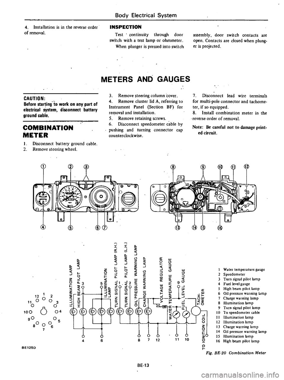
Fig
BE
20
Combination
Meter
1
Water
temperature
gauge
2
Speedometer
3
Turn
signal
pilot
lamp
4
Fuel
level
gauge
5
High
beam
pilot
lamp
6
Oil
pressure
warning
lamp
7
Charge
warning
lamp
8
Illumination
lamp
9
Turn
signal
pilot
lamp
10
To
speedometer
cable
11
Illumination
lamp
12
Illumination
lamp
13
Charge
warning
lamp
14
Oil
pressure
warning
lamp
15
Illumination
lamp
16
High
beam
pilot
lamp
12
1
11
00
o
100
6
gO
80
0
7
2
o
3
o
04
Os
o
6
U
4
u
6
BE125D
BE13
Page 527 of 548
0
@
o
s
xl
m
u
U
0
0
xJ
l
1
I
9
0
I
K
s
0
0
en
o
o
l
me
0
r
U
0
I
@
0
0
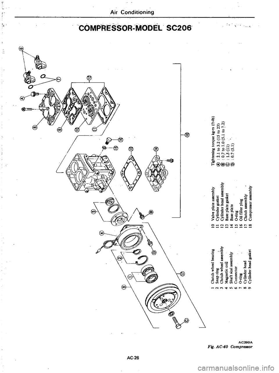
Tightening
torque
kg
m
ft
Ib
I
Clutch
wheel
bearing
10
Valve
pla
te
assembly
2
Snap
ring
11
Cylinder
gasket
@
i
1
to
3
2
IS
to
23
C
l
3
Clutch
wheel
alsembly
12
Cylinder
head
assembly
@
O
to
1
0
5
1
to
7
2
0
4
Magnetic
coil
13
B
plate
gasket
@
1
5
11
5
Shaft
seal
assembly
14
Bale
plate
@
0
7
5
1
6
Connector
IS
a
ting
7
O
ring
16
au
filler
plug
i
8
Cylindet
head
17
Clutch
assembly
o
Q
9
CyUhder
head
gasket
18
Compreslor
assembly
Page 528 of 548
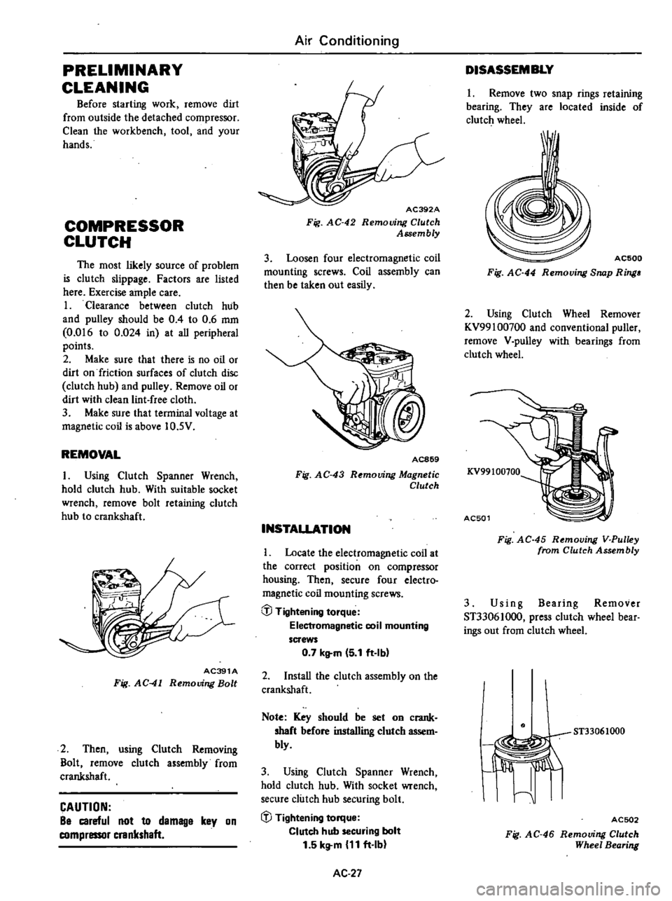
PRELIMINARY
CLEANING
Before
starting
work
remove
dirt
from
outside
the
detached
compressor
Clean
the
workbench
tool
and
your
hands
COMPRESSOR
CLUTCH
The
most
likely
source
of
problem
is
clutch
slippage
Factors
are
listed
here
Exercise
ample
care
1
Clearance
between
clutch
hub
and
pulley
should
be
0
4
to
0
6
mm
0
016
to
0
024
in
at
aU
peripheral
points
2
Make
sure
that
there
is
no
oil
or
dirt
on
friction
surfaces
of
clutch
disc
clutch
hub
and
pulley
Remove
oil
or
dirt
with
clean
lint
free
cloth
3
Make
sure
that
terminal
voltage
at
magnetic
coil
is
above
10
5V
REMOVAL
I
Using
Clutch
Spanner
Wrench
hold
clutch
hub
With
suitable
socket
wrench
remove
bolt
retaining
clutch
hub
to
crankshaft
AC391A
Fig
AC
41
Removing
Bolt
2
Then
using
Clutch
Removing
Bolt
remove
clutch
assembly
from
crankshaft
CAUTION
Be
careful
not
to
demage
key
on
compressor
crankshaft
Air
Conditioning
AC392A
Fig
AC
42
Removing
Clutch
Assembly
3
Loosen
four
electromagnetic
coil
mounting
screws
Coil
assembly
can
then
be
taken
out
easily
AC869
Fig
AC
43
R
mouing
Magnetic
Clutch
INSTALLATION
Locate
the
electromagnetic
coil
at
the
correct
position
on
compressor
housing
Then
secure
four
electro
magnetic
coil
mounting
screws
@
Tightening
torque
Electromagnetic
coil
mounting
screws
0
7
kltm
5
1
ft
Ibl
2
InstaU
the
clutch
assembly
on
the
crankshaft
Note
Key
should
be
set
on
crank
shaft
before
installing
clutch
assem
bly
3
Using
Clutch
Spanner
Wrench
hold
clutch
hub
With
socket
wrench
secure
clutch
hub
securing
bolt
iJJ
Tightening
torque
Clutch
hub
securing
bolt
1
5
kg
m
11
ft
Ib
AC
27
DISASSEMBLY
1
Remove
two
snap
rings
retaining
bearing
They
are
located
inside
of
clutch
wheel
I
AC500
Fig
AC
44
Removing
Snap
Ring
2
Using
Clutch
Wheel
Remover
KV99100700
and
conventional
puller
remove
V
pulley
with
bearings
from
clutch
wheel
KV99100100
AC501
Fig
AC
45
Removing
V
Pulley
from
Clutch
Assembly
3
Us
i
n
g
Bearing
Remover
ST33061000
press
clutch
wheel
bear
ings
out
from
clutch
wheel
ST33061000
I
Jiffi
I
ACSD2
Fig
AC
46
Removing
Clutch
Wheel
Bearing
Page 529 of 548
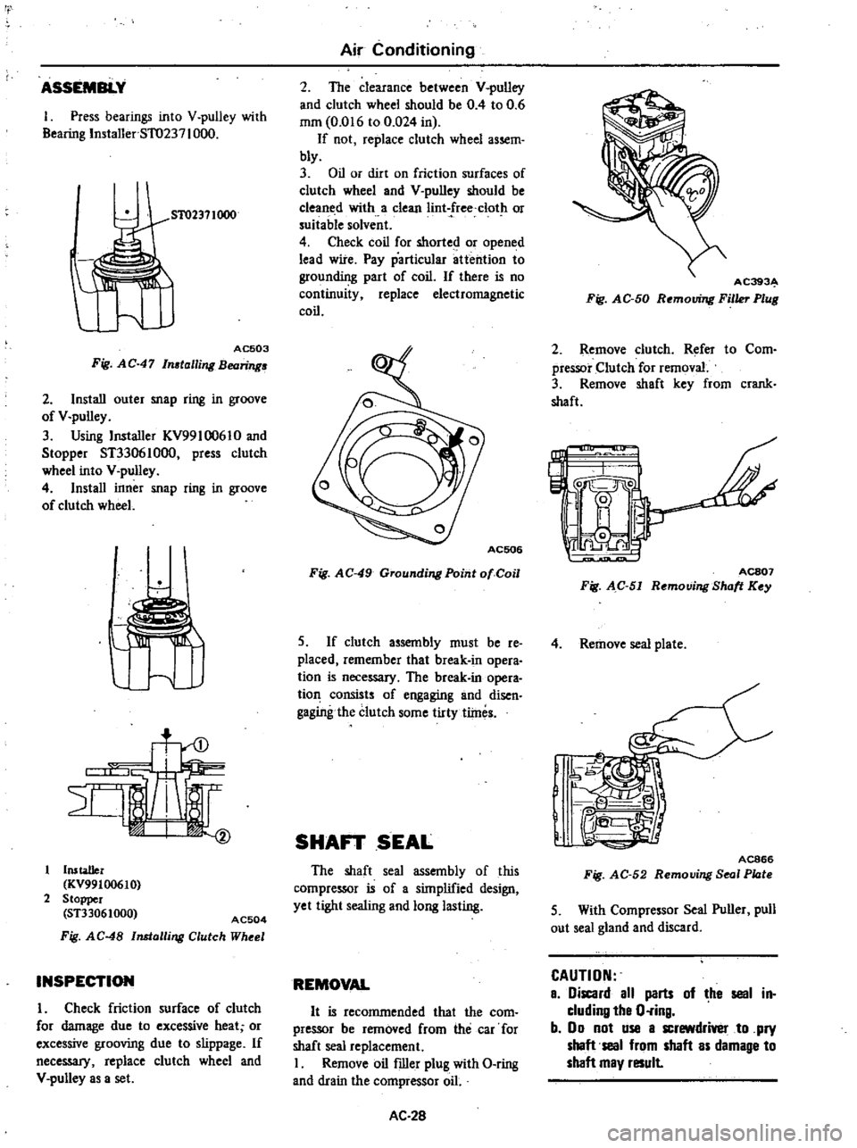
rt
ASSEMBLY
1
Press
bearings
into
V
pulley
with
Bearing
Installer
5T0237
1000
51
02371000
AC503
Fig
AC
47
In
talling
Bearing
2
Install
outer
snap
ring
in
groove
of
V
pulley
3
Using
Installer
KV99l
0061
0
and
Stopper
ST33061000
press
clutch
wheel
into
V
pulley
4
Install
inner
snap
ring
in
groove
of
clutch
wheel
u
Installer
KV99100610
2
Stopper
ST33061000
AC504
Fig
AC
48
Installing
Clutch
Wheel
INSPECTION
I
Check
friction
surface
of
clutch
for
damage
due
to
excessive
heat
or
excessive
grooving
due
to
slippage
If
neceSS3I
replace
clutch
wheel
and
V
pulley
as
a
set
Air
Conditioning
2
The
clearance
between
V
pulley
and
clutch
wheel
should
be
0
4
to
0
6
mm
0
016
to
0
024
in
If
not
replace
clutch
wheel
assem
bly
3
Oil
or
dirt
on
friction
surfaces
of
clutch
wheel
and
V
pulley
should
be
cleaned
with
a
clean
Iint
free
clot
or
suitable
solvent
4
Check
coil
for
shorted
or
opened
lead
wire
Pay
particular
attention
to
grounding
part
of
coil
If
there
is
no
continuity
replace
electromagnetic
coil
Fig
AC
49
Grounding
Point
01
Coil
S
If
clutch
assembly
must
be
re
placed
remember
that
break
in
opera
tion
is
neceSS3I
The
break
in
opera
tion
consists
of
engaging
and
disen
gagingthe
clutch
some
tirty
tlines
SHAFT
SEAL
The
shaft
seal
assembly
of
this
compressor
is
of
a
simplified
design
yet
tight
sealing
and
long
lasting
REMOVAL
It
is
recommended
that
the
com
pressor
be
removed
from
the
car
for
shaft
seal
replacement
I
Remove
oil
filler
plug
with
O
ring
and
drain
the
compressor
oil
AC
28
AC393
Fig
AC
50
Removing
Filler
Plug
2
Remove
clutch
Refer
to
Com
pressor
Clutch
for
removal
3
Remove
shaft
key
from
crank
shaft
L
IJ
C
I
0
ACS07
Fig
AC
51
Removing
Shott
Key
4
Remove
seal
plate
J
e
I
@
IR
n
1
j
AC866
Fig
AC
52
Removing
Seal
Plote
5
With
Compressor
Seal
Puller
pull
out
seal
gland
and
discard
CAUTION
a
iscard
all
parts
of
he
seal
in
cluding
tha
O
ring
b
00
not
use
a
screwdrivel
to
pry
shaft
seal
from
shaft
as
damage
to
shaft
may
result
Page 545 of 548
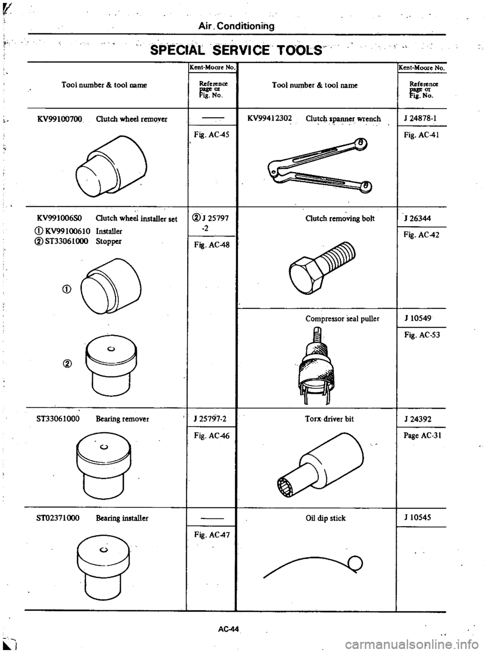
v
Air
Conditioning
SPECIAL
SERVICE
TOOLS
Tool
number
tool
name
KV99100700
Clutch
wheel
remover
KV99I006SO
CD
KV9910061
0
@ST33061llOO
Clutch
wheel
installer
set
Installer
Stopper
CD
@
ST3306IOOO
Bearing
remover
ST02371
000
Bearing
installer
l
K
ent
Moore
No
Reference
ftr
N
Fig
AC
45
@J25797
2
Fig
AC
48
J
25797
2
Fig
AC
46
Fig
AC
47
AC44
Tool
number
tool
name
KV99412302
Clutch
spanner
wrench
Clutch
removing
bolt
Compressor
seal
puller
Torx
driver
bit
Oil
dip
stick
Kent
Moore
No
Reference
J
24878
1
Fig
AC
41
J
26344
Fig
AC
42
J
10549
Fig
AC
53
J
24392
Page
AC
31
J
10545