wheel DATSUN 210 1979 Service Manual
[x] Cancel search | Manufacturer: DATSUN, Model Year: 1979, Model line: 210, Model: DATSUN 210 1979Pages: 548, PDF Size: 28.66 MB
Page 3 of 548
DATSUN
210
SERVICE
MANUAL
Model
8310
Series
T
OfOUoW
lTY
INISSAN
N
OIlCOIIO
NISSAN
MOTOR
CO
LTD
17
1
Ginza
6
Chome
Chuo
ku
Tokyo
104
Japan
QUICK
REFERENCE
INDEX
GENERAL
INFORMATION
GI
ENGINE
TUNE
UP
ET
ENGINE
MECHANICAL
EM
ENGINE
LUBRICATION
SYSTEM
EL
COOLING
SYSTEM
CO
ENGI
NE
FUEL
EF
EMISSION
CONTROL
SYSTEM
EC
ENGINE
ELECTRICAL
SYSTEM
EE
ENGINE
REMOVAL
INSTALLATION
ER
CLUTCH
CL
lMr
MANUAL
TRANSMISSION
MT
AUTOMATIC
TRANSMISSION
AT
H
PROPELLER
SHAFT
OIFFERENTlAL
CARRIER
PO
FRONT
AXLE
FRONT
SUSPENSION
FA
10
REAR
AXLE
REAR
SUSPENSION
RA
BRAKE
SYSTEM
BR
WHEEL
A
NO
TI
RE
WT
0
STEERING
SYSTEM
ST
ENGINE
CONTROL
FUEL
EXHAUST
SYSTEMS
FE
BOOY
BF
BOOY
ELECTRICAL
SYSTEM
BE
AIR
CONOITIONING
AC
Page 13 of 548
General
Information
LIFTING
POINTS
AND
TOWING
PANTOGRAPH
JACK
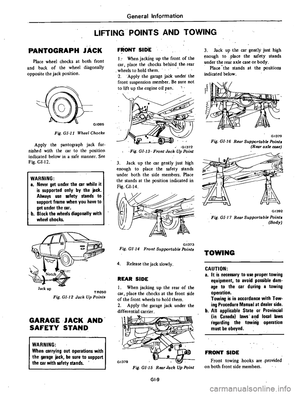
Place
wheel
chocks
at
both
front
and
back
of
the
wheel
diagonally
opposite
the
jack
position
GIOB5
Fig
GI
I
I
Wheel
Chocks
Apply
the
pantograph
jack
fur
nished
with
the
car
to
the
position
indicated
below
in
a
safe
manner
See
Fig
GI
12
WARNING
a
Never
get
under
the
car
while
it
is
supported
only
by
the
jack
Always
use
safety
stands
to
support
frame
when
you
have
to
get
under
the
car
b
Block
the
wheels
diagonally
with
wheel
chocks
Jack
up
TROSO
Fig
GI
12
Jack
Up
Points
GARAGE
JACK
AND
SAFETY
STAND
WARNING
When
carrying
out
operations
with
the
garage
jack
be
sure
to
support
the
car
with
safety
stands
FRONT
SID
E
I
When
jacking
up
the
front
of
the
car
place
the
chocks
behind
the
rear
wheels
to
hold
them
2
Apply
the
garage
jack
under
the
front
suspension
member
Be
sure
not
to
lift
up
the
engine
oil
pan
GI372
Fig
GI
13
Front
Jack
Up
Point
3
Jack
up
the
car
gently
just
high
enough
to
place
the
safety
stands
under
both
the
side
members
Place
the
stands
at
the
position
indicated
in
Fig
GI
14
GI373
Fig
GI
14
Front
Supportable
Point
4
Release
the
jack
slowly
REAR
SIDE
When
jacking
up
the
rear
of
the
car
place
the
chocks
at
the
front
side
of
the
front
wheels
to
hold
them
2
Apply
the
garage
jack
under
the
differential
carrier
1
1
Il
GI378
Fig
GI
15
Rear
Jack
Up
Point
GI
9
3
Jack
up
the
car
gently
just
high
enough
to
place
the
safety
stands
under
the
rear
axle
case
or
body
Place
the
stands
at
the
positions
indicated
below
GI379
Fig
GI
16
Rear
Supportable
Point
Rear
axle
c
rue
GI392
Fig
01
17
Rear
Supportable
Point
Body
TOWING
CAUTION
a
It
is
necemry
to
use
proper
towing
equipment
to
avoid
possible
dam
age
to
the
car
during
a
towing
operation
Towing
is
in
accordance
with
Tow
ing
Procedure
Manual
at
dealer
side
b
All
applicable
State
or
Provincial
in
Canada
laws
and
local
laws
regarding
the
towiilg
operation
must
be
obeyed
FRONT
SIDE
Front
towing
hooks
are
provided
on
both
front
side
members
Page 14 of 548
GI417
Fig
GI
15
Front
Towing
Hook
REAR
SIDE
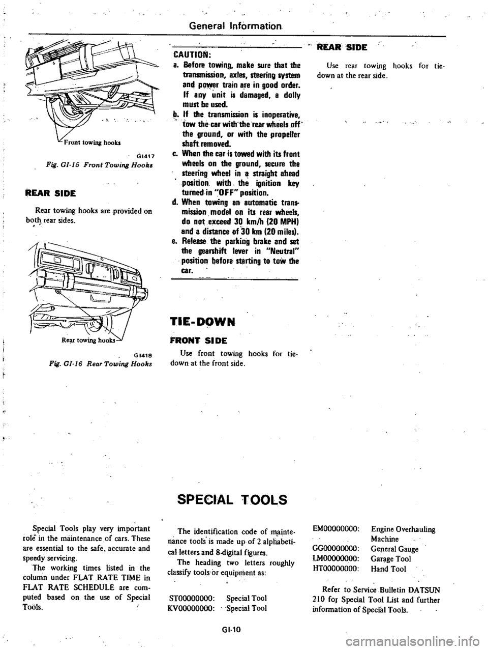
Rear
towing
hooks
are
provided
on
bot
rear
sides
GI418
Fig
GI
16
Rear
Towing
Hooks
Special
Tools
play
very
important
role
in
the
maintenance
of
cars
These
are
essential
to
the
safe
accurate
and
speedy
servicing
The
working
times
listed
in
the
column
under
FLAT
RATE
TIME
in
FLAT
RATE
SCHEDULE
are
com
puted
based
on
the
use
of
Special
Tools
General
Information
CAUTION
a
Before
towing
make
sure
that
the
transmission
axles
steering
system
and
p
r
train
are
in
good
order
If
any
unit
is
damaged
a
dolly
must
be
used
If
the
transmission
is
inoperative
tow
the
car
with
the
rear
wheels
off
the
ground
or
with
the
propeller
shaft
removed
c
When
the
car
is
towed
with
its
front
wheels
on
the
ground
secure
the
steering
wheel
in
a
straight
ahead
position
with
the
ignition
key
turnedin
OFF
position
d
When
towing
an
automatic
trans
mission
model
on
its
rear
wheels
do
not
exceed
30
km
h
20
MPH
and
a
distance
of30
km
20
miles
e
Release
the
parking
brake
and
set
the
gearshift
lever
in
Neutral
position
before
starting
to
tow
the
car
TIE
DOWN
FRONT
51
DE
Use
front
towing
hooks
for
tie
down
at
the
front
side
SPECIAL
TOOLS
The
identification
code
of
ffi
linte
nance
tools
is
made
up
of
2
alphabeti
calletters
and
8
digital
figures
The
heading
two
letters
roughly
classify
tools
c
equipment
as
STOOOOOOOO
KVOOOOOOOO
Special
Tool
Special
Tool
GI
l0
REAR
SIDE
Use
rear
towing
hooks
for
tie
down
at
the
rear
side
EMOOOOOOOO
GGOOOOOOOO
lMOOOOOOOO
HTOOOOOOOO
Engine
Overhauling
Machine
General
Gauge
Garage
Tool
Hand
Tool
Refer
to
Service
Bulletin
DATSUN
210
fOJ
Special
Tool
List
and
further
information
of
Special
Tools
Page 19 of 548
sion
pressure
chances
are
that
piston
rings
are
worn
or
damaged
2
If
pressure
stays
low
the
likeli
hood
is
that
valve
is
sticking
or
seating
Engine
Tune
up
improperly
3
If
cylinder
compression
in
any
two
adjacent
cylinders
is
low
and
if
adding
oil
does
not
help
the
compres
sion
there
is
leakage
past
the
gasketed
surface
Oil
and
water
in
combustion
cham
bers
can
result
from
this
problem
IGNITION
AND
FUEL
SYSTEM
CHECKING
BATTERY
I
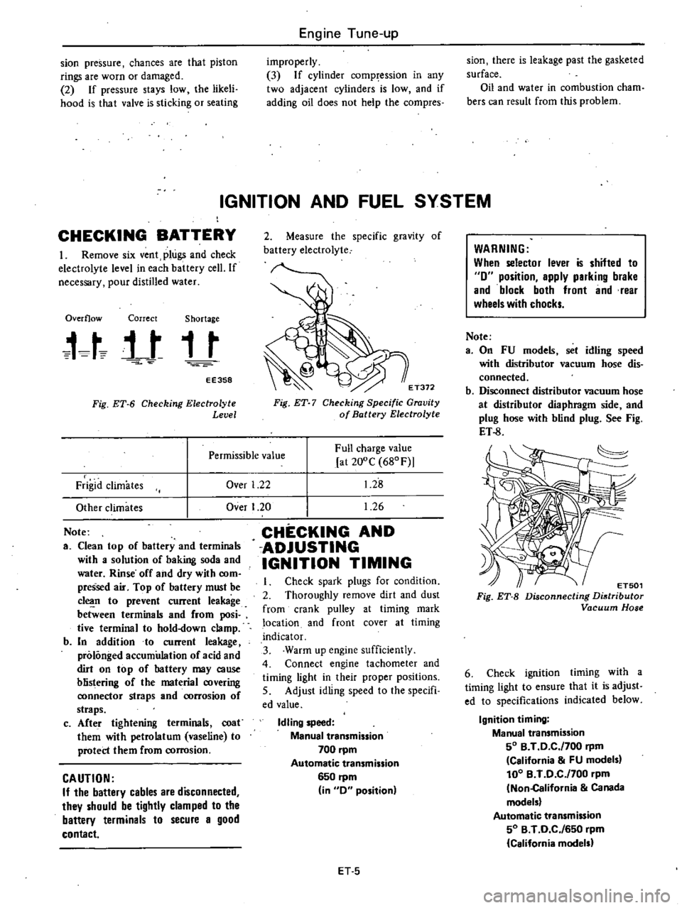
Remove
six
vent
plugs
and
check
electrolyte
level
in
each
battery
cell
If
necessary
pour
distilled
water
Overflow
Correct
Shortage
t
t
j
t
t
t
EE358
Fig
ET
6
Checking
Electrolyte
Level
2
Measure
the
specific
gravity
of
battery
electrolyte
E
T372
Fig
ET
7
Checking
Specific
Gravity
of
Battery
Electrolyte
Over
1
22
Full
charge
value
at
200C
680F
1
28
1
26
Permissible
value
Frigid
climates
Other
climates
Note
a
Clean
top
of
battery
and
terminals
with
a
solution
of
baking
soda
and
water
Rinse
off
and
dry
with
com
pressed
air
Top
of
battery
must
be
c1
n
to
prevent
current
leakage
between
terminals
and
from
posi
tive
terminal
to
hold
down
clamp
b
In
addition
to
current
leakage
prolonged
accumulation
of
acid
and
dirt
on
top
of
hattery
may
cause
blistering
of
the
material
covering
ronnector
straps
and
rorrosion
of
straps
c
Afte
r
tightening
terminals
coat
them
with
petrolatum
vaseline
to
protect
them
from
corrosion
CAUTION
If
the
battery
cables
are
disconnected
they
should
be
tightly
clamped
to
the
battery
terminals
to
secure
a
good
contact
Over
I
20
CHECKING
AND
ADJUSTING
IGNITION
TIMING
Check
spark
plugs
for
condition
2
Thoroughly
remove
dirt
and
dust
from
crank
pulley
at
timing
mark
location
and
front
cover
at
timing
indicator
3
Warm
up
engine
sufficiently
4
Connect
engine
tachometer
and
timing
light
in
their
proper
positions
5
Adjust
idling
speed
to
the
specifi
ed
value
Idling
speed
Manual
transmission
700
pm
Automatic
transmission
6S0
rpm
in
0
position
ET
S
WARNING
When
selector
lever
is
shifted
to
0
position
apply
parking
brake
and
block
both
front
and
rear
wheels
with
chocks
Note
a
On
FU
models
set
idling
speed
with
distributor
vacuum
hose
dis
connected
b
Disconnect
distributor
vacuum
hose
at
distributor
diaphragm
side
and
plug
hose
with
blind
plug
See
Fig
ET
8
ET501
Fig
ET
B
Disconnecting
Distributor
Vacuum
Hose
6
Check
ignition
timing
with
a
timing
light
to
ensure
that
it
is
adjust
ed
to
specifications
indicated
below
Ignition
timing
Manual
transmission
SO
B
T
0
C
f700
rpm
California
FU
models
100
B
T
0
C
f700
pm
Non
California
Canada
models
Automatic
transmission
SO
B
T
0
C
f6S0
rpm
California
models
Page 21 of 548
CHECKING
AND
ADJUSTING
CARBURETOR
IDLE
RPM
AND
MIXTURE
RATIO
WARNING
a
0
n
a
utomatic
transmission
models
checks
should
be
per
formed
with
the
lever
shifted
to
the
0
position
Be
sure
to
engage
parking
brake
and
to
lock
both
front
and
rear
wheels
with
wheel
chocks
b
Oepress
brake
pedal
while
ac
celerating
the
engine
to
prevent
forward
surge
of
car
c
After
idle
adjustment
has
been
made
shift
the
lever
to
the
N
or
P
positfon
and
remove
wheel
chocks
CAUTION
00
not
attempt
to
screw
the
idle
adjusting
screw
down
completely
00
ing
so
could
cause
damage
to
tip
which
in
turn
will
tend
to
cause
malfunctions
Note
a
When
measuring
CO
percentage
in
sert
probe
into
tail
pipe
more
than
40
cm
15
7
in
b
In
thee
case
of
air
conditioner
e
quipped
models
the
idle
adjust
ment
should
be
carried
out
while
the
air
conditioner
is
OFF
c
When
making
idle
adjustment
do
not
removt
air
cleaner
CO
Idle
adJustment
with
CO
meter
Idle
mixture
adjustment
requires
the
use
of
a
CO
meter
especially
for
California
models
When
preparing
to
adjust
idle
mixture
it
is
essential
to
have
the
meter
thoroughly
warmed
up
and
calibrated
1
Check
carburetor
pipes
for
proper
connection
2
Warm
up
engine
until
water
tern
perature
indicator
points
to
the
middle
of
gauge
The
procedure
to
warm
up
J
Engine
Tune
up
engine
is
not
specifically
recom
mended
Either
driving
car
or
operat
ing
engine
at
no
load
will
be
good
3
Make
sure
that
water
temperature
indicator
points
to
the
middle
Further
keep
engine
running
at
about
2
000
rpm
for
about
5
minutes
without
applying
load
to
engine
in
order
to
stabilize
engine
condition
Engine
hood
should
be
open
4
Run
engine
for
about
10
minutes
at
idling
speed
During
this
10
minutes
proceed
as
described
in
steps
5
to
9
below
5
I
Disconnect
air
hose
from
air
check
valve
and
install
cap
on
air
check
valve
Except
Canada
and
FU
models
EF244
Fig
ET
11
Disconnecting
Air
Hose
from
Air
Check
Valve
Except
Canada
and
FU
models
Canada
and
FU
models
2
Disconnect
air
hose
from
air
induction
pipe
and
install
cap
on
air
induction
pipe
Canada
and
FU
mod
els
EF849
Fig
ET
12
Installing
Cap
on
Air
Induction
Pipe
FU
models
3
On
FU
models
disconnect
dis
tributor
vacuum
hose
at
distributor
diaphragm
side
and
plug
hose
with
blind
plug
ET
7
ET501
Fig
ET
13
Disconnecting
Distributor
Vacuum
Hose
6
Race
engine
I
500
to
2
OOO
rpm
two
or
three
times
under
no
load
then
run
engine
for
one
minute
at
idling
speed
7
Adjust
throttle
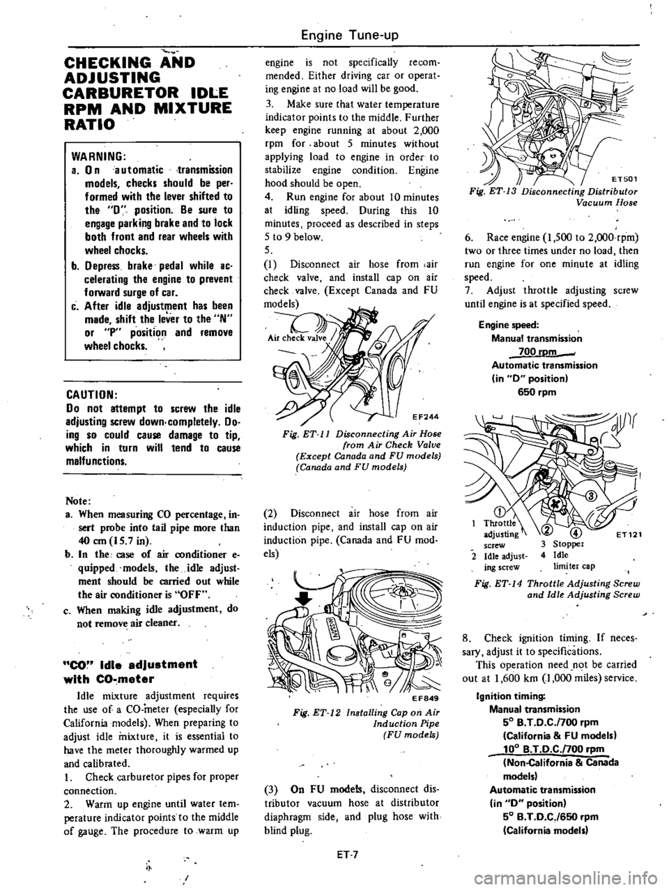
adjusting
screw
until
engine
is
at
specified
speed
Engine
speed
Manual
transmission
700
rDm
Automatic
transmission
in
0
position
650
rpm
2
Fig
ET
14
Throttle
Adjusting
Screw
and
Idle
Adjusting
Screw
8
Check
ignition
timing
If
neces
sary
adjust
it
to
specifications
This
operation
need
n
t
be
carried
out
at
1
600
km
1
000
miles
service
Ignition
timing
Manual
transmission
50
B
T
0
C
f700
rpm
California
FU
models
100
B
T
O
C
noo
rpm
Non
California
Canada
models
Automatic
transmission
in
0
position
50
B
T
0
CJ650
rpm
California
model
Page 39 of 548
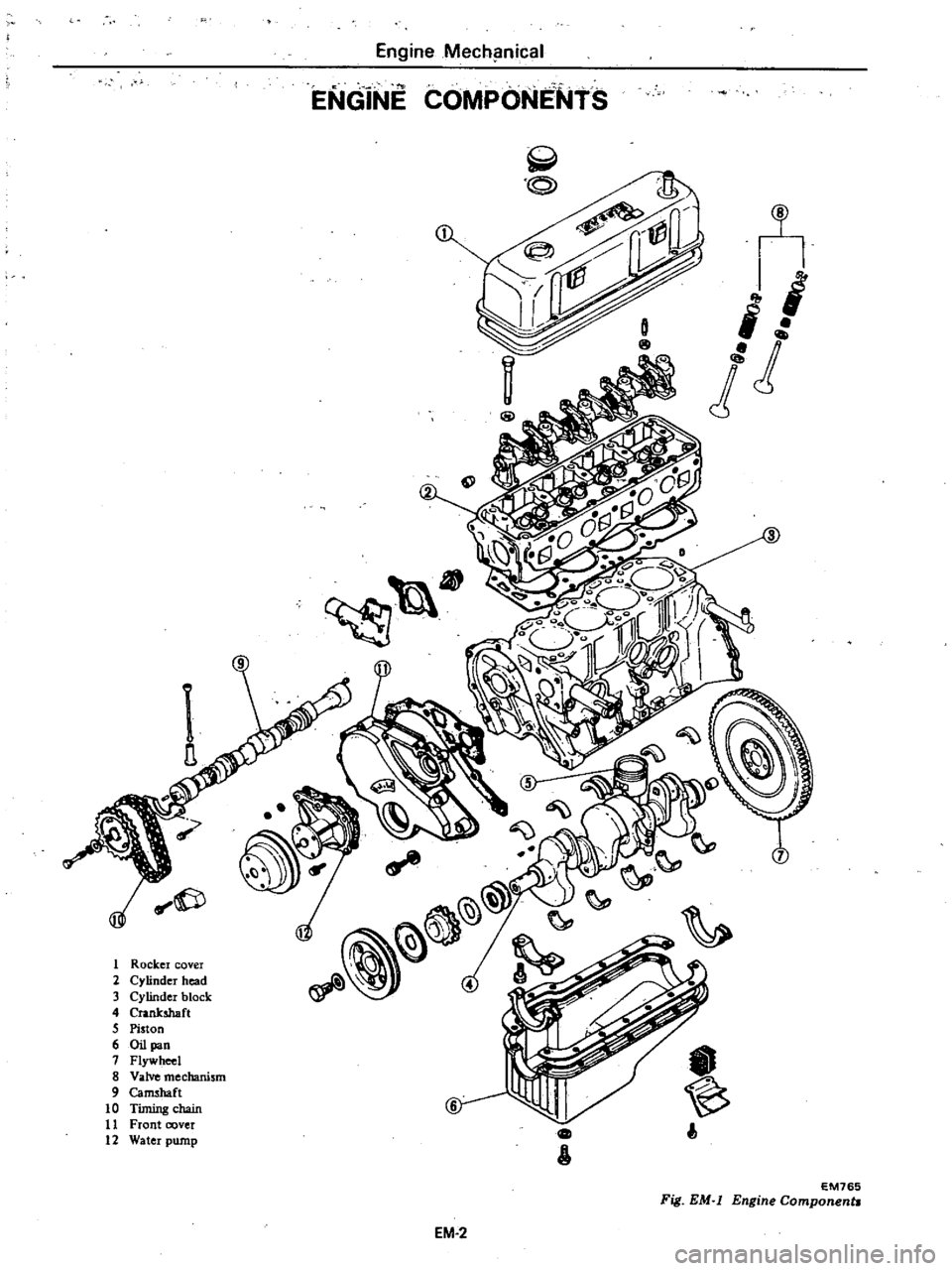
1
Rockel
covel
2
Cylindel
head
3
Cylinder
block
4
Cnnksbaft
5
Piston
6
Oil
pan
7
Flywheel
8
Valve
mechanism
9
Cam
haft
10
Timing
chain
11
Front
cover
12
Watel
pump
Engine
Mech
lnical
ENGiNE
COMPONENtS
I
I
I
ld
n
t
I
EM765
Fig
EM
l
Engine
ComponentJ
EM
2
Page 41 of 548
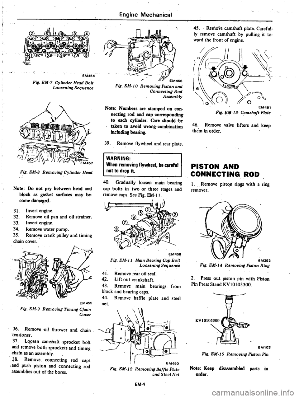
EMA
54
Fig
EM
7
Cylinder
Head
Bolt
Looaening
S
quence
Fig
EM
8
Removing
Cylinder
Ht
ad
Note
Do
not
pry
between
head
and
block
as
gasket
surfaces
may
be
come
damaged
31
Invert
engine
32
Remove
oil
pan
and
oil
strainer
33
Invert
engine
34
kemove
water
pump
35
Remove
crank
pulley
and
timing
chain
cover
EMA
55
Fig
EM
9
Removing
Timing
Chain
Cover
36
Remove
i1
thrower
and
chain
tensioner
37
LQ9sen
camshaft
sprocket
bolt
and
remove
both
procket
and
timing
chain
an
assembly
3
Remove
connecting
rod
caps
and
push
piston
and
connecting
rod
assemblies
out
of
the
bores
Engine
Mechanical
hi
r
EM456
Fig
EM
l
0
Remooing
Piston
and
Connecling
Rod
Assembly
Note
Numbers
are
stamped
on
con
necting
rod
and
cap
rllnding
to
each
cylinder
Care
should
be
taken
to
avoid
wrong
comhination
including
bearing
39
Remove
flywheel
and
rear
plate
WARNING
When
remnving
flywheel
be
careful
not
to
drop
it
40
Gradually
loosen
main
bearing
cap
bolt
in
two
or
three
stages
and
remove
caps
See
Fig
EM
II
I
l
P
@
D
M458
Fig
EM
ll
Main
Bearing
Cap
Bolt
Loo
ning
Sequ
nce
41
Remove
rear
oil
seal
42
Lift
out
crankshaft
43
Remove
main
bearings
from
block
and
bearing
caps
44
Remove
baffie
plate
and
tee
net
EM460
Fig
EM
l2
Remooing
Baffle
Plate
and
Steel
Net
EM
4
45
RemoVe
camshaft
plate
Careful
ly
remove
camshaft
by
pulling
it
to
ward
the
front
of
engine
EM461
Fig
EM
j3
Camshaft
Plate
46
Remove
valve
lifter
and
keep
them
in
order
PISTON
AND
CONNECTING
ROD
I
Remove
piston
rings
with
a
ring
remover
EM292
Fig
EM
14
Remooing
PUton
Ring
2
Press
out
piston
pin
with
Piston
Pin
Press
Stand
KVIOIOS300
EM103
Fig
EM
15
R
moving
Piston
Pin
Note
Keep
disassembled
parts
in
order
Page 48 of 548
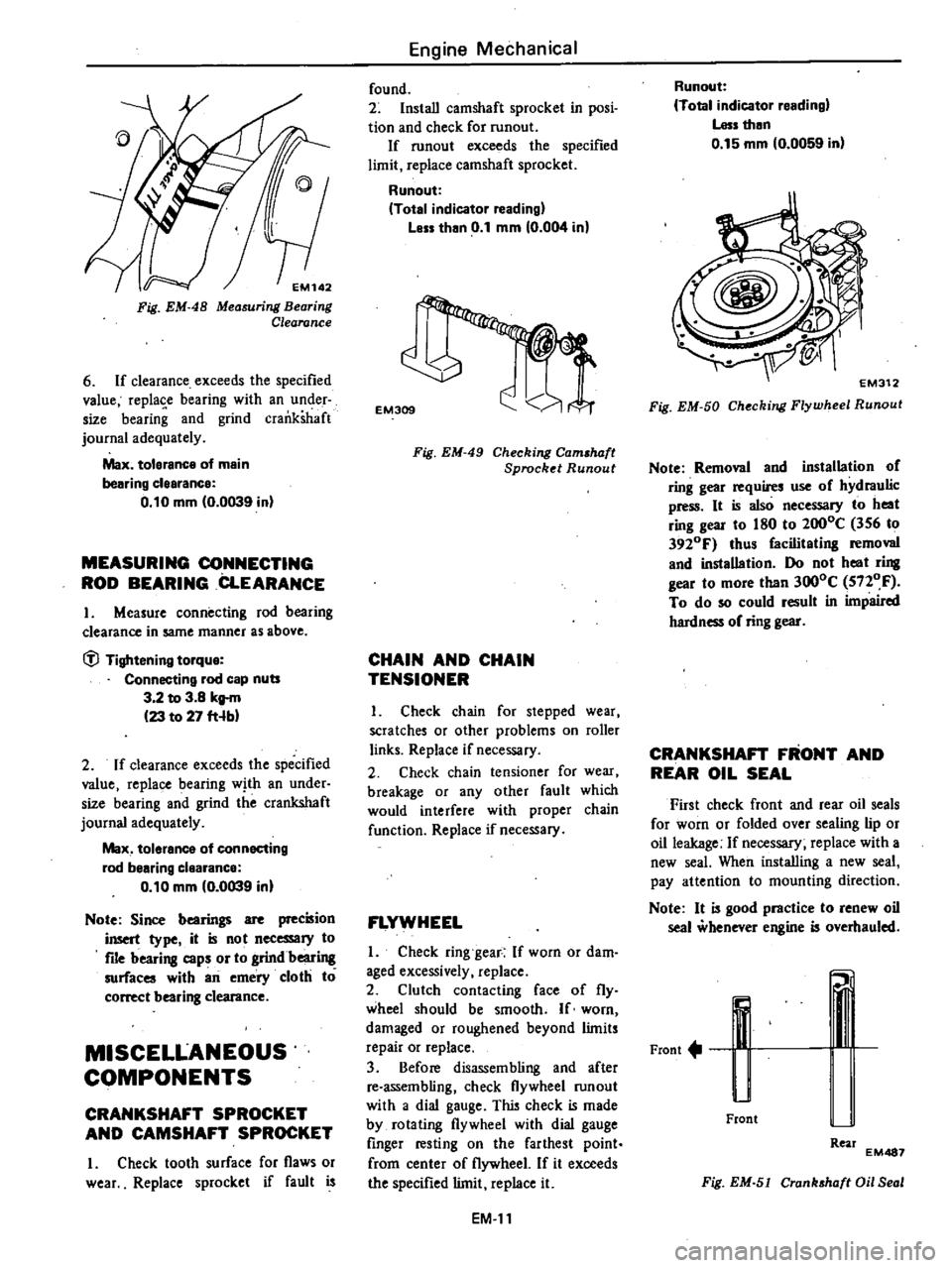
EM142
Fig
EM
48
Measuring
Bearing
Clearance
6
If
clearance
exceeds
the
specified
value
replase
bearing
with
an
under
size
bearing
and
grind
crankshaft
journal
adequately
Max
tolerance
of
main
bearing
clearance
0
10
mm
0
0039
in
MEASURING
CONNECTING
ROD
BEARING
CLEARANCE
I
Measure
connecting
rod
bearing
clearance
in
same
manner
as
above
tfl
Tightening
torque
Connecting
rod
cap
nuts
3
2
to
3
8
kg
m
23
to
27
fHb
2
If
clearance
exceeds
the
specified
value
replace
bearing
with
an
under
size
bearing
and
grind
the
crankshaft
journal
adequately
Max
tolerance
of
connecting
rod
bearing
clearance
0
10
mm
0
0039
in
Note
Since
bearings
are
precision
insert
type
it
is
not
necessary
to
file
bearing
caps
or
to
grindbeari
surfaces
with
an
emery
cloth
to
correct
bearing
clearance
MISCELLANEOUS
COMPONENTS
CRANKSHAFT
SPROCKET
AND
CAMSHAFT
SPROCKET
I
Check
tooth
surface
for
flaws
or
wear
Replace
sprocket
if
fault
is
Engine
Mechanical
found
2
Install
camshaft
sprocket
in
posi
tion
and
check
for
runout
If
runout
exceeds
the
specified
limit
replace
camshaft
sprocket
Runout
Total
indicator
reading
Less
than
0
1
mm
0
004
in
EM309
Fig
EM
49
Checking
Cam
haft
Sprocket
Runout
CHAIN
AND
CHAIN
TENSIONER
I
Check
chain
for
stepped
wear
scratches
or
other
problems
on
roller
links
Replace
if
necessary
2
Check
chain
tensioner
for
wear
breakage
or
any
other
fault
which
would
interfere
with
proper
chain
function
Replace
if
necessary
FLYWHEEL
I
Check
ring
gear
If
worn
or
dam
aged
excessively
replace
2
Clutch
contacting
face
of
fly
wheel
should
be
smooth
If
worn
damaged
or
roughened
beyond
limits
repair
or
replace
3
Before
disassembling
and
after
re
assembling
check
flywheel
run
out
with
a
dial
gauge
This
check
is
made
by
rotating
flywheel
with
dial
gauge
finger
resting
on
the
farthest
point
from
center
of
flywheel
If
it
exceeds
the
specified
limit
replace
it
EM
II
Runout
Total
indicator
reading
Less
then
0
15
mm
0
0059
in
Fig
EM
50
Checking
Flywheel
Runout
Note
Removal
and
installation
of
ring
gear
requires
use
of
hydraulic
press
It
is
also
necessary
to
heat
ring
gear
to
180
to
2000C
356
to
3920F
thus
facilitating
removal
and
installation
Do
not
heat
ring
gear
to
more
than
3000C
5nOF
To
do
so
could
result
in
impaired
hardness
of
ring
gear
CRANKSHAFT
FRONT
AND
REAR
OIL
SEAL
First
check
front
and
rear
oil
seals
for
worn
or
folded
over
sealing
lip
or
oil
leakage
If
necessary
replace
with
a
new
seal
When
installing
a
new
seal
pay
attention
to
mounting
direction
Note
It
is
good
practice
to
renew
oil
seal
whenever
engine
is
overhauled
Front
u
Front
Rear
EM487
Fig
EM
51
Cranhhaft
Oil
Seal
Page 51 of 548
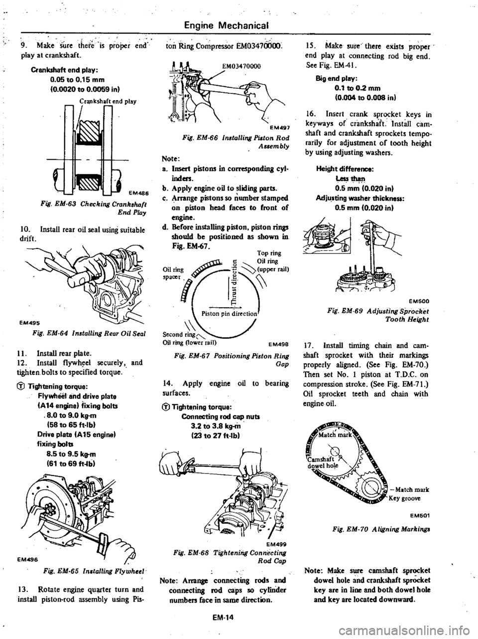
9
Make
SUre
there
is
proper
end
play
at
crankshaft
Crankshaft
end
play
0
05toO
15mm
0
OO20
to
0
0059
in
laJlk
h
end
play
J
EM486
Fig
EM
63
Checking
Crank
luJft
End
Play
10
Install
rear
oil
seal
using
suitable
drift
Fig
EM
64
n
talling
Rear
Oil
Seal
II
Install
rear
plate
12
Install
flywh
el
secwely
and
tighten
bolts
to
specified
torque
dl
Tightening
torque
Flywheel
and
drive
plate
A
14
engine
fixing
bolts
8
0
to
9
0
kg
m
58
to
65
ft
Ib
Drive
plate
A
15
engine
fixing
bolts
8
5
to
9
5
kg
m
61
to
69
ft
b
Fig
EM
65
n
talling
Flywheel
13
Rotate
engine
quarter
turn
and
install
piston
rod
assembly
using
Pis
Engine
Mechanical
ton
Ring
Compressor
EM03470000
EM497
Fig
EM
66
tolling
Platon
Rod
Assem
bly
Note
a
Insert
pistons
in
L
r
nding
cyl
inders
b
Apply
engine
oil
to
sliding
parts
c
Arrange
pistons
so
number
stamped
on
piston
head
faces
to
front
of
engine
d
Before
installing
piston
piston
rings
should
be
positioned
as
shown
in
Fig
EM
67
Second
ring
Oil
ring
lower
rail
EM49B
Fig
EM
67
Positioning
Piston
Ring
Gap
14
Apply
engine
oil
to
bearing
surfaces
dl
Tighte
ning
torque
Connecting
rod
cap
nuts
3
2
to
3
8
kg
m
23
to
27
ft
b
EM499
Fig
EM
68
Tightening
Connecting
Rod
Cap
Note
Am11
connecting
rods
and
connecting
rod
caps
so
cylinder
numben
face
in
same
direction
EM
14
I
S
Make
sure
there
exists
proper
end
play
at
connecting
rod
big
end
See
Fig
EM41
Big
end
play
0
1
to
0
2
mm
0
004
to
0
008
in
16
Insert
crank
sprocket
keys
in
keyways
of
crankshaft
Install
cam
shaft
and
crankshaft
sprockets
tempo
rarily
for
adjustment
of
tooth
height
by
using
adjusting
washers
Height
dif
Less1
h
l11
0
5
mm
0
020
in
Adjusting
washer
thickness
0
5
mm
10
020
in
EM500
Fig
EM
69
Adju
ting
Sprocket
Tooth
Height
17
Install
tinting
chain
and
cam
shaft
sprocket
with
their
markings
properly
aligned
See
Fig
EM
70
Then
set
No
I
piston
at
T
D
C
on
compression
stroke
See
Fig
EM
71
Oil
sprocket
teeth
and
chain
with
engine
oil
Match
mark
Key
groove
EM501
Fig
EM
70
Aligning
Markinga
Note
Make
sure
camshaft
sprocket
dowel
hole
and
crankshaft
sprocket
key
are
in
line
and
both
dowel
hole
and
key
are
located
downward
Page 66 of 548

Engine
Mechanical
Main
bearing
undersize
Unit
mm
in
Main
bearing
undersi
ze
Crank
journal
diameter
Standard
size
49
943
to
49
964
1
9663
to
1
9671
0
25
0
0098
49701
to
49
714
1
9567
to
1
9572
Undersize
0
50
0
0197
49451
to
49
464
1
9469
to
1
9474
0
75
0
0295
49
201
to
49
214
1
9370
to
1
9376
Connecting
rod
bearing
undersize
Unit
mm
in
Connecting
rod
bearing
undersize
Crank
pin
diameter
Standard
size
44
954
to
44
974
1
7698
to
I
7706
0
08
0
0031
44
881
to
44
894
1
7670
to
1
7675
0
25
0
0098
44
711
to
44
724
1
7603
to
1
7608
Undersize
0
50
0
0197
44
461
to
44
474
1
7504
to
1
7509
0
75
0
0295
44
211
to
44
224
1
7406
to
I
7411
MISCELLANEOUS
COMPONENTS
Unit
mm
in
Max
tolerance
Runout
of
camshaft
0
1
0
004
0
15
0
0059
Runout
of
flywheel
EM
29