Combination switch DATSUN 210 1979 Service Manual
[x] Cancel search | Manufacturer: DATSUN, Model Year: 1979, Model line: 210, Model: DATSUN 210 1979Pages: 548, PDF Size: 28.66 MB
Page 104 of 548
1
Ignition
switch
2
Amplifier
3
Speed
switch
Note
a
Tightening
torque
is
1
8
to
2
2
kg
m
13
to
16
ft
Ib
b
After
replacement
start
engine
and
check
to
be
sure
that
fuel
is
not
leaking
and
that
anti
dieseling
sole
noid
i
in
good
condition
EFOSOA
Fig
EF47
Checking
Anti
dieaeling
Solenoid
l
SJ
Engine
Fuel
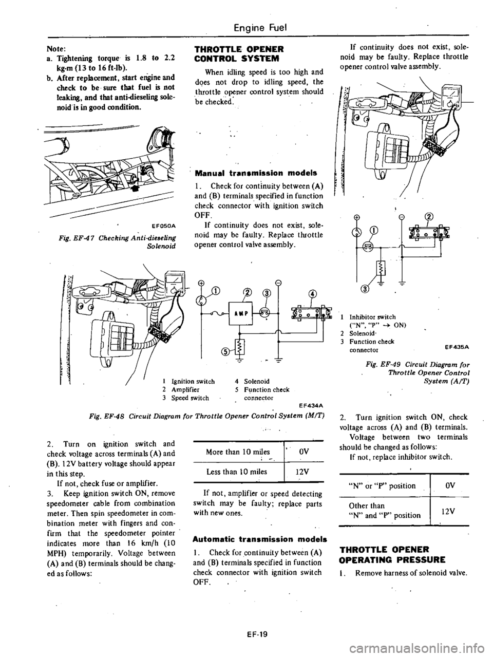
THROTTLE
OPENER
CONTROL
SYSTEM
When
idling
speed
is
too
high
and
does
not
drop
to
idling
speed
the
throttle
opener
control
system
should
be
checked
Manual
transmission
models
I
Check
for
continuity
between
A
and
8
terminals
specified
in
function
check
connector
with
ignition
switch
OFF
If
continuity
does
not
exist
sole
noid
may
be
faulty
Replace
throttle
opener
control
valve
assembly
e
1J
3
o
0
5
4
Solenoid
5
F
nction
check
connector
EF434A
Fig
EF
48
Circuit
Diagram
for
Throttle
Opener
Control
System
MIT
2
Turn
on
ignition
switch
and
check
voltage
across
terminals
A
and
8
l2V
battery
voltage
should
appear
in
this
step
If
not
check
fuse
or
amplifier
3
Keep
ignition
switch
ON
remove
speedometer
cable
from
combination
meter
Then
spin
speedometer
in
com
bination
meter
with
fingers
and
con
firm
that
the
speedometer
pointer
indicates
more
than
16
km
h
10
MPH
temporarily
Voltage
between
A
and
8
terminals
should
be
chang
ed
as
follows
More
than
10
miles
OV
Less
than
10
miles
12V
If
not
amplifier
or
speed
detecting
switch
may
be
faulty
replace
parts
with
new
ones
Automatic
transmission
models
I
Check
for
continuity
between
A
and
8
terminals
specified
in
function
check
connector
with
ignition
switch
OFF
EF
19
If
continuity
does
not
exist
sole
noid
may
be
faulty
Replace
throttle
opener
control
valve
assembly
If
t
r
If
I
Inhibitor
switch
N
p
ON
2
Solenoid
3
Function
check
connector
EF43SA
Fig
EF
49
Circuit
Diagram
for
Throttle
Opener
Control
System
AfT
2
Turn
ignition
switch
ON
check
voltage
across
A
and
8
terminals
Voltage
between
two
terminals
should
be
changed
as
follows
If
not
replace
inhibitor
switch
N
or
p
position
OV
Other
than
N
and
p
position
l2V
THROTTLE
OPENER
OPERATING
PRESSURE
I
Remove
harness
of
solenoid
valve
Page 386 of 548
STEERING
LOCK
To
provide
tamper
proof
self
shear
type
screws
are
used
and
their
heads
are
sheared
off
when
installed
so
that
the
steering
lock
system
cannot
be
removed
easily
REMOVAL
I
Break
two
self
shear
type
screws
with
a
drill
or
other
proper
tool
Steering
System
2
Remove
two
screws
and
dismount
steering
lock
from
steering
jacket
tube
ST393
Fig
ST
5
Removing
Steering
Lock
Securing
Screw
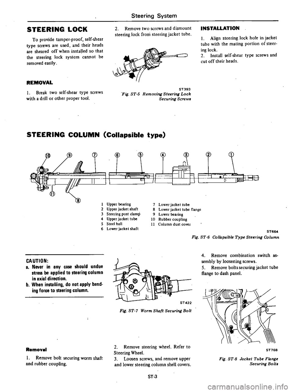
STEERING
COLUMN
Collapsible
type
1
H
f
II
CAUTION
a
Never
in
any
case
should
undue
strass
be
applied
to
steering
column
in
axial
direction
b
Whan
installing
do
not
apply
bend
ing
force
to
steering
column
Removel
I
Remove
bolt
securing
worm
shaft
and
rubber
coupling
INSTALLATION
I
Align
steering
lock
hole
in
jacket
tube
with
the
mating
portion
of
steer
ing
lock
2
Install
self
shear
type
screws
and
cut
off
their
heads
i
4
T
C
F
Lu
J
r
1
V
F
1
Upper
bearing
2
Upper
jacket
shaft
3
Steering
post
clamp
4
Upper
jacket
tube
5
Steel
ball
6
Lower
jacket
shaft
7
Lower
jacket
tube
8
Lower
jacket
tube
flange
9
Lower
bearing
10
Rubber
coupling
11
Column
dust
cover
it
j
a
ST
422
Fig
ST
7
Worm
8lwft
Securing
Bolt
2
Remove
steering
wheel
Refer
to
Steering
Wheel
3
Loosen
screws
and
remove
upper
and
lower
steering
column
shell
covers
ST
3
ST664
Fig
8T
6
Collapsibte
Type
Steoring
Column
4
Remove
combination
switch
as
sembly
by
loosening
screws
5
Remove
baIts
securing
jacket
tube
flange
to
dash
panel
ST768
Fig
8T
8
Jacket
Tube
Flange
Securing
Bolt
Page 446 of 548
DATSUN
210
Model
8310
Series
SECTIONBE
BODY
ELECTRICAL
SYSTEM
CONTENTS
BODY
ELECTRICAL
WIRING
DESCRIPTION
FUSE
AND
FUSIBLE
LINK
WIRING
WIRING
HARNESS
LOCATION
OF
ELECTRICAL
UNIT
ELECTRICAL
UNIT
OF
LIGHTING
SYSTEM
BULB
SPECIFICATIONS
REMOVAL
AND
INSTALLATION
For
lamp
IGNITION
SWITCH
COMBINATION
SWITCH
ILLUMINATION
CONTROL
UNIT
AIMING
ADJUSTMENT
ELECTRICAL
UNIT
OF
SIGNAL
SYSTEM
BE
12
TURN
SIGNAL
SWITCH
BE
12
HORN
RELAY
BE
12
HAZARD
SWITCH
BE
12
STOP
LAMP
SWITCH
BE
12
BACK
UP
LAMP
SWITCH
BE
12
DOOR
SWITCH
BE
12
METERS
AND
GAUGES
BE
13
COMBINATION
METER
BE
13
TACHOMETER
BE
14
FUEL
LEVEL
AND
WATER
TEMPERATURE
INDICATOR
SYSTEM
BE
14
WARNING
SYSTEM
BE
15
CHARGE
WARNING
SYSTEM
BE
15
BRAKE
WARNING
SYSTEM
BE
15
BE
2
BE
2
BE
2
BE
4
BE
5
BE
8
BE
9
BE
9
BE
10
BE
10
BE
10
BE
11
BE
11
OIL
PRESSURE
WARNING
SYSTEM
SEAT
BELT
WARNING
SYSTEM
ELECTRICAL
ACCESSORIES
WINDSHIELD
WIPER
AND
WASHER
REAR
WINDOW
WIPER
AND
WASHER
CIGARETTE
LIGHTER
RADIO
CLOCK
REAR
WINDOW
DEFOGGER
STARTING
SYSTEM
For
automatic
transmission
models
HEATER
DESCRIPTION
AIR
FLOW
REMOVAL
AND
INSTALLATION
ADJUSTING
HEATER
CONTROL
DISASSEMBLY
AND
ASSEMBLY
OF
HEATER
UNIT
INSPECTION
WIRING
DIAGRAMS
AND
TROUBLE
DIAGNOSES
ELECTRICAL
SYSTEM
BLOCK
DIAGRAM
FUSE
BLOCK
CIRCUIT
SUPPLY
ROUTING
LIGHTING
SYSTEM
SIGNAL
SYSTEM
METERS
AND
GAUGES
WARNING
SYSTEM
ELECTRICAL
ACCESSORY
SYSTEM
HEATER
BE
15
BE
15
BE
17
BE
17
BE
18
BE
20
BE
20
BE
21
BE
21
BE
23
BE
23
BE
23
BE
24
BE
26
BE
27
BE
27
BE
28
BE
29
BE
29
BE
30
BE
31
BE
36
BE
41
BE
44
BE
4B
BE
55
Page 450 of 548
m
c
n
to
l
l
I
g
iF
0
1
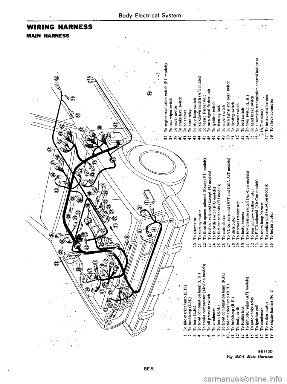
To
side
marker
lamp
L
H
2
To
headlamp
L
H
3
To
horn
L
H
4
To
front
combination
lamp
L
H
5
To
cooler
co
pressor
Air
Con
models
6
To
oil
pressure
switch
7
To
condenser
8
To
horn
R
H
9
To
front
combination
la
t11p
R
H
10
To
side
marker
lamp
R
H
11
To
headlamp
R
H
12
To
body
earth
13
To
fusible
link
14
To
inhibitor
relay
AfT
model
15
To
aut6
choke
relay
16
To
ignition
coil
17
To
condenser
18
To
washer
motor
19
To
engine
harness
No
2
@
20
To
alternator
21
To
starting
motor
22
To
throttle
opener
solenoid
Except
FU
models
23
To
fuel
cut
solenoid
Except
FU
models
24
To
throttle
switch
FU
models
25
To
fuel
cut
solenoid
FU
models
26
To
auto
choke
27
To
VC
cut
solenoid
M
T
and
Calif
AfT
models
28
To
distributor
29
To
thermal
transmitter
30
To
body
harness
31
To
low
pressure
switcn
Air
Con
models
32
To
rear
window
washer
motor
33
To
FICO
solenoid
Air
Con
models
34
To
room
lamp
harness
35
To
cooling
unit
Air
C
on
models
36
To
heater
motor
37
To
engine
revolution
switch
FU
models
38
To
rear
wiper
switch
39
To
wiper
motor
40
To
brake
level
switch
41
To
belt
timer
42
To
horn
relay
43
To
stop
lamp
switch
44
To
kickdown
switch
AfT
model
45
To
hazard
flasher
unit
46
To
turn
signal
flasher
unit
47
To
ignition
switch
48
To
steering
lock
49
To
wiper
switch
50
To
turn
signal
and
hC
rn
switch
51
To
lighting
switch
5i
To
hazard
switch
53
To
belt
switch
54
To
door
switch
L
H
55
To
hand
brake
switch
56
To
automatic
transmission
control
indicator
AfT
models
57
To
instrument
harness
58
To
check
connector
I
0
i
a
z
Z
G
z
tIl
tIl
a
Z
Il
I
to
o
Co
m
16
n
n
OJ
1
3
Page 451 of 548
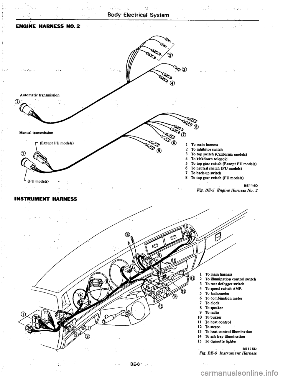
BodyElectrital
System
ENGINE
HARNESS
NO
2
@
Automatic
transmission
Manual
transmission
j
Except
FU
models
1
To
main
harness
2
To
inhibitor
switch
3
To
top
tch
California
models
4
To
kicJcdown
solenoid
5
To
top
gear
switch
Except
FU
models
6
To
neutral
switch
FU
models
7
To
back
up
switch
8
To
top
gear
switch
FU
models
BE1140
Fig
BE
5
Engine
Hame
No
2
INSTRUMENT
HARNESS
1
To
main
harness
2
To
illumination
control
switch
3
To
rear
defogger
switch
4
To
Ipeed
witch
AMP
5
To
tachometer
6
To
combination
meter
7
To
clock
8
To
speaker
9
To
radio
10
To
buzzer
11
To
heat
control
12
To
stereo
13
To
heat
control
illumination
14
To
ash
tray
illumination
15
To
cigarette
lighter
BE115D
Fig
BE
6
Instrument
Harne
BE
6
Page 452 of 548
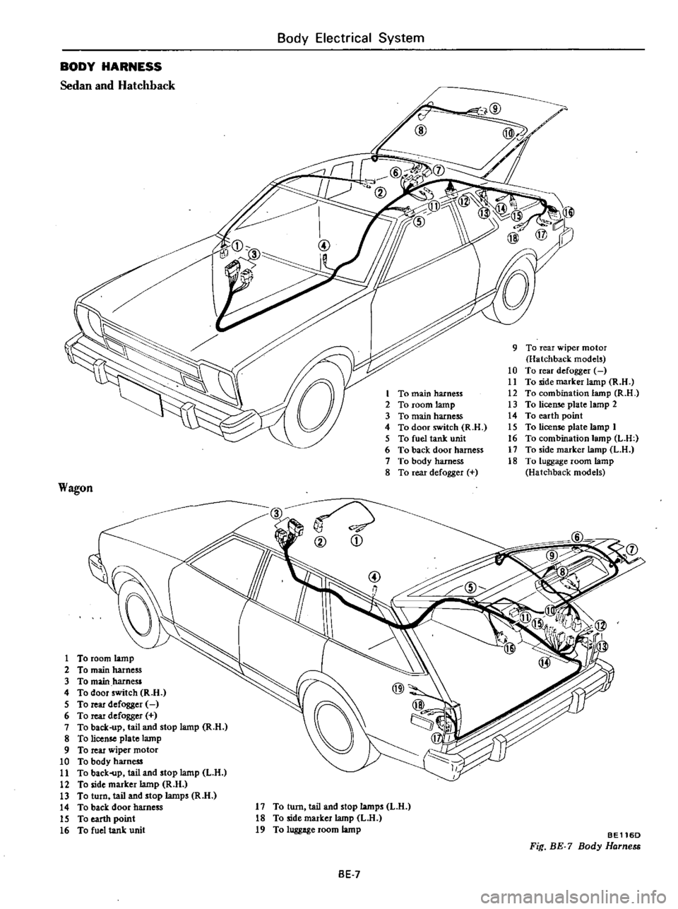
Body
Electrical
System
BODY
HARNESS
Sedan
and
Hatchback
9
To
rear
wiper
motor
Hatchback
models
10
To
rear
defogger
11
To
side
marker
lamp
R
H
12
To
combination
lamp
R
n
13
To
license
plate
lamp
2
14
To
earth
point
15
To
license
plate
lamp
1
16
To
combination
lamp
L
U
17
To
side
marker
lamp
L
H
18
To
luggage
room
lamp
Hatchback
models
Wagon
D
S
3
To
main
hamess
4
To
door
switch
R
n
5
To
rear
defogger
6
To
rear
defogger
7
To
back
up
tail
and
stop
lamp
R
H
8
To
license
plate
lamp
9
To
rear
wiper
motor
10
To
body
harness
11
To
baek
p
tail
and
stop
lamp
L
H
12
To
side
marker
lamp
R
H
13
To
turn
tail
and
stop
lamps
R
n
14
To
back
door
harness
15
To
earth
point
16
To
fuel
tank
unit
@
Yj
qr
@
D
17
To
turn
tail
and
stop
lamps
L
H
18
To
side
marker
lamp
L
U
19
To
luggage
room
lamp
BE116D
Fig
BE
7
Body
Harness
BE
7
Page 455 of 548
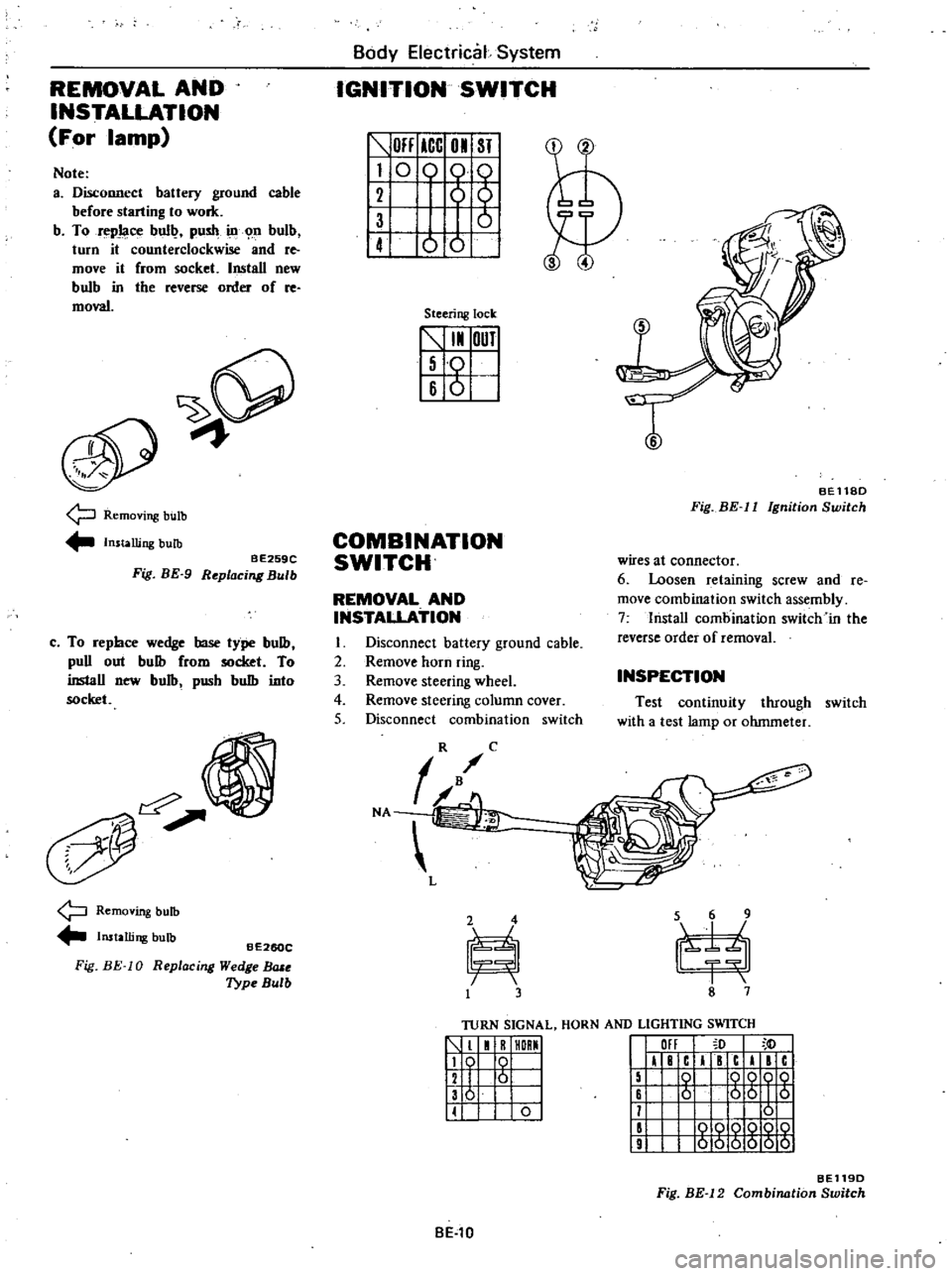
REMOVAL
AND
INSTALLATION
For
lamp
Note
a
Disconnect
battery
ground
cable
before
starting
to
work
b
To
repJaoe
bull
push
ill
n
bulb
turn
it
counterclockwise
and
re
move
it
from
socket
Install
new
bulb
in
tbe
reverse
order
of
re
moval
9
Removing
bulb
Installing
bulb
BE259C
Fig
BE
9
Replacing
Bulb
c
To
repbce
wedge
base
type
bulb
puD
out
bulb
from
socket
To
inslaD
new
bulb
pusb
bulb
into
socket
Removing
bulb
Installing
bulb
Fig
BE
10
BE260C
R
eplac
ing
Wedge
BlUe
Type
Bulb
Body
Electrical
System
IGNITION
SWITCH
OFF
ICC
01
ST
I
0
0
61
1
ot
Steering
lock
5
I
OUT
I
Iso
16
6
I
T
BEll8D
Fig
BE
II
Ignition
Switch
COMBINATION
SWITCH
wires
at
connector
6
Loosen
retaining
screw
and
Ie
move
combination
switch
assembly
7
lnstaD
combination
switch
in
the
reverse
order
of
removal
REMOVAL
AND
INSTALLATION
I
Disconnect
battery
ground
cable
2
Remove
horn
ring
3
Remove
steering
wheel
4
Remove
steering
column
cover
5
Disconnect
combination
switch
INSPECTION
Test
continuity
through
switch
with
a
test
lamp
or
ohmmeter
TURN
SIGNAL
HORN
AND
LIGHTING
SWITCH
1
1
R
HORMI
119
0
I
12
I
6
I
136
I
II
0
I
III
I
F
c
I
c
I
c
15
0
QQOQ
16
6
56
I
5
11
0
II
000Q
10
9
000000
BE119D
Fig
BE
12
Combination
Switch
BE
l0
Page 457 of 548
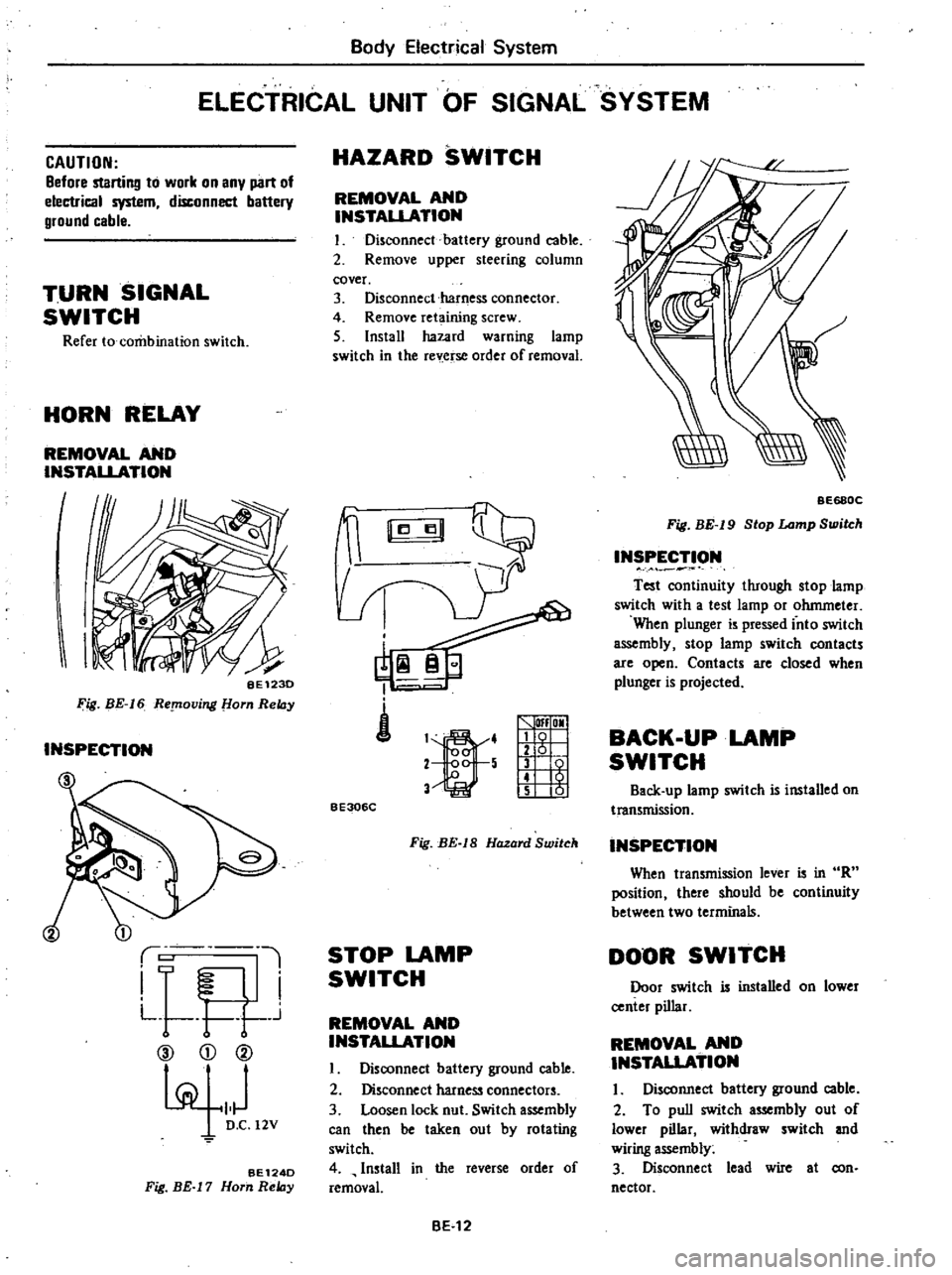
Body
Electrical
System
ELECTRICAL
UNIT
OF
SIGNAL
SYSTEM
CAUTION
Before
startill1l
to
work
on
any
part
of
electrical
system
disconnect
battery
ground
cable
TURN
SIGNAL
SWITCH
Refer
to
combination
switch
HORN
RELAY
REMOVAL
AND
INSTALLATION
I
I
BE123D
Fig
BE
16
ReplOving
om
ReIDy
INSPECTION
1
i
L
l
I
F
I
L
t
r
j
CV
CD
@
pi
101
D
C
12V
BE124D
Fig
BE
17
Horn
ReIDy
HAZARD
SWITCH
REMOVAL
AND
INSTAUATION
I
Disconnect
battery
ground
cable
2
Remove
upper
steering
column
cover
3
Disconnect
harness
connector
4
Remove
ret
ining
screw
5
Install
hazard
warning
lamp
switch
in
the
rev
erse
order
of
removal
i
1
4
2
5
V
lfI
OMI
g
1
t
5
01
BE306C
Fig
BE
IS
Hazard
Switch
STOP
LAMP
SWITCH
REMOVAL
AND
INSTALLATION
I
Disoonnect
battery
ground
cable
2
Disconnect
harness
connectors
3
Loosen
lock
nut
Switch
assembly
can
then
be
taken
out
by
rotating
switch
4
Install
in
the
reverse
order
of
removal
BE
12
BE68QC
Fig
BE
19
Stop
Lamp
Switch
INSPECTION
Test
oontinuity
through
stop
lamp
switch
with
a
test
lamp
or
ohmmeter
When
plunger
is
pressed
into
switch
assembly
stop
lamp
switch
contacts
are
open
Contacts
are
closed
when
plunger
is
projected
BACK
UP
LAMP
SWITCH
Back
up
lamp
switch
is
installed
on
transmission
INSPECTION
When
transmission
lever
is
in
R
position
there
should
be
continuity
between
two
terminals
DOOR
SWITCH
Door
switch
is
installed
on
lower
center
pillar
REMOVAL
AND
INSTAUATION
I
Disconnect
battery
ground
cable
2
To
pull
switch
assembly
out
of
lower
pillar
withdraw
switch
and
wiring
assembly
3
Disconnect
lead
wire
at
con
nector
Page 458 of 548
Body
Electrical
System
INSPECTION
4
Installation
is
in
the
reverse
order
of
removal
Test
continuity
through
door
switch
with
a
test
lamp
or
ohmmeter
When
plunger
is
pressed
into
switch
assembly
door
switch
contacts
are
open
Contacts
are
closed
when
plung
er
is
projected
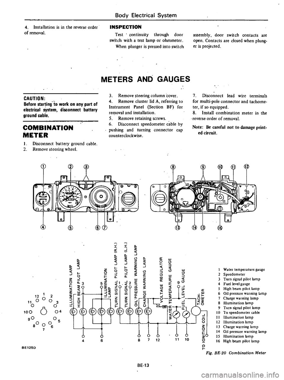
METERS
AND
GAUGES
3
Remove
steering
column
cover
4
Remove
cluster
lid
A
referring
to
Instrument
Panel
Section
BF
for
reqlOval
and
installation
5
Remove
retaining
screws
6
Disconnect
speedometer
cable
by
pushing
and
turning
connector
cap
counterclockwise
7
Disconnect
lead
wire
terminals
for
multi
pole
connector
and
tachome
ter
if
so
equipped
8
Install
combination
meter
in
the
reverse
order
of
removal
CAUTION
Before
starting
to
work
on
any
part
of
electrical
sYstem
disconnect
battery
ground
cable
COMBINATION
METER
Note
Be
careful
not
to
damage
print
ed
circuit
I
Disconnect
battery
ground
cable
2
Remove
steering
wheel
CD
Cl
B
i
lJ
Q
@
8
0
I
0
w
@
@
I
Q
a
d
Q
Q
J
Q
2
Cl
0
a
w
Q
3
j
J
Z
t
0
J
W
C
I
0
9
J
CI
C
CI
J
0
I
Q
a
Cl
w
z
J
w
Z
a
c
o
0
3
S2
J1
J2
a
a
l
gO
C
4
l
w
I
EO
l
c
zO
zO
1
Cl
CjU
z
3
Q
Q
w
c
ffi
ffi
to
J
C
U
en
a
C
a
w
i
r
@
p
g10
l
0
U
lJ
v
v
zO
8
7
12
11
10
Q
o
I
Fig
BE
20
Combination
Meter
1
Water
temperature
gauge
2
Speedometer
3
Turn
signal
pilot
lamp
4
Fuel
level
gauge
5
High
beam
pilot
lamp
6
Oil
pressure
warning
lamp
7
Charge
warning
lamp
8
Illumination
lamp
9
Turn
signal
pilot
lamp
10
To
speedometer
cable
11
Illumination
lamp
12
Illumination
lamp
13
Charge
warning
lamp
14
Oil
pressure
warning
lamp
15
Illumination
lamp
16
High
beam
pilot
lamp
12
1
11
00
o
100
6
gO
80
0
7
2
o
3
o
04
Os
o
6
U
4
u
6
BE125D
BE13
Page 463 of 548
CAUTION
a
Be
sure
to
use
only
windshield
washing
solution
Never
mix
soap
powder
or
deter
gent
with
solution
b
To
avoid
improper
windshield
washer
operation
do
not
operate
windshield
washer
continuously
for
more
than
30
seconds
or
without
washer
fluid
Normally
windshield
washer
should
be
operated
for
10
seconds
or
less
at
one
time
Wiper
and
washer
switch
When
removing
wiper
and
washer
switch
remove
combination
switch
Refer
to
Lighting
and
Turn
Signal
Switch
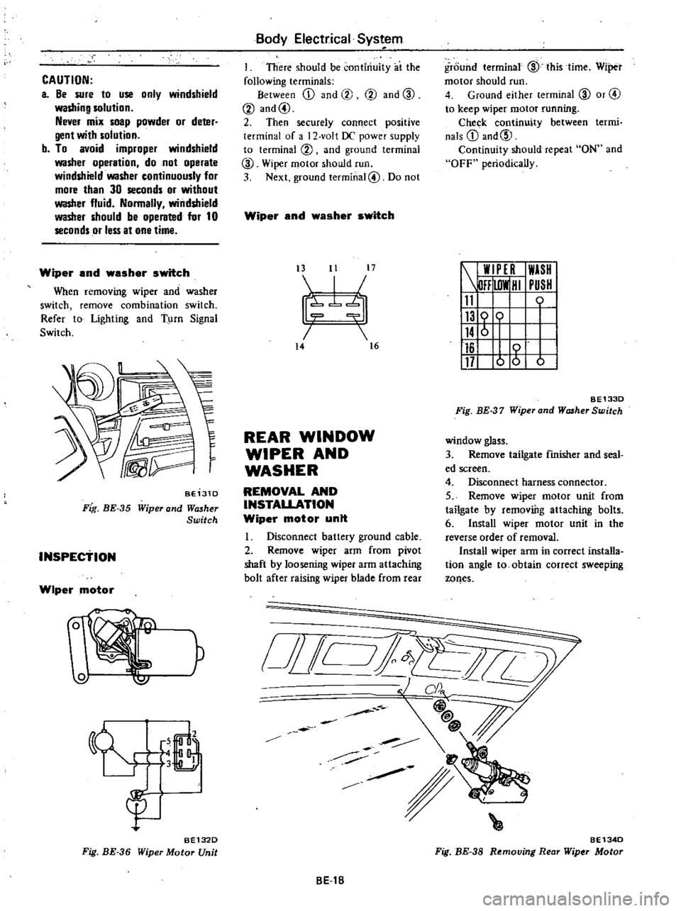
BE131D
Fig
BE
35
Wiper
and
Wll5her
Switch
INSPEctiON
Wiper
motor
W
P
6
LJ
3
B
gu
BE132D
Fig
BE
36
Wiper
Motor
Unit
Body
Electrical
Sys
em
I
There
should
be
continuity
at
the
following
terminals
Between
ill
and
@
@
and
CID
@
and@
2
Then
securely
connect
positive
terminal
of
a
2
volt
DC
power
supply
to
terminal
@
and
ground
terminal
CID
Wiper
motor
should
run
3
Next
ground
terminal@
Do
not
Wiper
and
washer
switch
t3
11
17
I
7b
14
16
REAR
WINDOW
WIPER
AND
WASHER
REMOVAL
AND
INSTALLATION
Wiper
motor
unit
Disconnect
battery
ground
cable
2
Remove
wiper
arm
from
pivot
shaft
by
loosening
wiper
arm
attaching
bolt
after
raising
wiper
blade
from
rear
o
i
Jill
BE1B
ground
terminal
CID
this
time
Wiper
motor
should
run
4
Ground
either
terminal
CID
or
@
to
keep
wiper
motor
running
Chec
k
continuity
between
termi
nals
ill
and@
Continuity
should
repeat
ON
and
OFF
periodically
W
PE
I
WASH
DFF
lOW
HI
PUSH
11
0
116
117
o
g
b
BE1330
Fig
BE
37
Wiper
and
WcuherSwitch
window
glass
3
Remove
tailgate
finisher
and
seal
ed
screen
4
Disconnect
harness
connector
5
Remove
wiper
motor
unit
from
tailgate
by
removiDg
attaching
bolts
6
Install
wiper
motor
unit
in
the
reverse
order
of
removal
Install
wiper
arm
in
correct
installa
tion
angle
to
obtain
correct
sweeping
wQes
BE134D
Fig
BE
38
Removing
Rear
Wiper
Motor