Signal light DATSUN 210 1979 Service Manual
[x] Cancel search | Manufacturer: DATSUN, Model Year: 1979, Model line: 210, Model: DATSUN 210 1979Pages: 548, PDF Size: 28.66 MB
Page 95 of 548
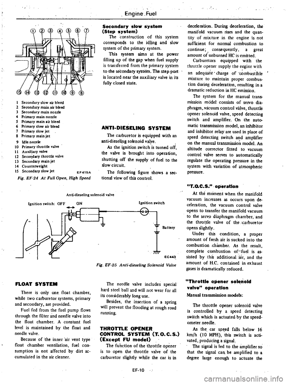
I
Secondary
slow
air
bleed
2
Secondary
main
air
bleed
3
Secondary
main
nozzle
4
Primary
main
nozzle
5
Primary
main
air
bleed
6
Primary
slow
air
bleed
7
Primary
slow
jet
8
Primary
main
jet
9
Idle
nozzle
10
Primary
throttle
valve
II
Auxiliary
valve
12
Seco
dary
throttle
valve
13
Secondary
main
jet
14
Counterweight
IS
Secondary
slow
jet
EF419A
Fig
EF
24
At
Full
Open
High
Speed
Engine
Fuel
Secondary
slow
system
Step
system
The
construction
of
this
system
corresponds
to
the
idling
and
slow
system
of
the
primary
system
This
system
aims
at
the
power
filling
up
of
the
gap
when
fuel
supply
is
transferred
from
the
primary
system
to
the
secondary
system
The
stepport
is
located
near
the
auxiliary
valve
in
its
fully
closed
state
ANTI
DIESELING
SYSTEM
The
carburetor
is
equipped
with
an
anti
liese1i
lg
solenoid
valye
As
the
ignition
switch
is
turned
off
the
valve
is
brought
into
operation
shutting
off
the
supply
of
fuel
to
the
slow
circuit
The
following
figure
shows
a
see
tional
view
of
this
control
An
ti
dies
eling
solenoid
valve
Ignition
switch
OFF
ON
t
L
li
FLOAT
SYSTEM
There
is
only
one
float
chamber
while
two
carburetor
systems
primary
and
secondary
are
provided
Fuel
fed
from
the
fuel
pump
flows
through
the
filter
and
needle
valve
into
the
float
chamber
A
constant
fuel
level
is
maintained
by
the
float
and
needle
valve
Because
of
the
inner
air
vent
type
float
chamber
ventilation
fuel
con
sumption
is
not
affected
by
dirt
ac
cumulated
in
the
air
cleaner
Ignition
switch
Q
1
T
Battery
niT
EC
3
Fig
EF
25
Anti
dieseling
Solenoid
Valve
The
needle
valve
includes
special
hard
steel
ball
and
wiD
not
wear
for
all
its
considerably
long
use
Besides
the
insertion
of
a
spring
will
prevent
the
flooding
at
rough
road
running
THROTTLE
OPENER
CONTROL
SYSTEM
T
O
C
S
Except
FU
model
The
function
of
the
throttle
opener
is
to
open
the
throttle
valve
of
the
carburetor
slightly
while
the
car
is
in
EF
10
deceleration
During
deceleration
the
manifold
vacuum
rises
and
the
quan
tity
of
mixture
in
the
engine
is
not
suffICient
for
normal
combustion
to
continue
4
consequently
a
great
amount
of
unburned
HC
is
emitted
Carburetors
equipped
with
the
throttle
opener
supply
the
engine
with
an
adequate
charge
of
combustible
mixture
to
maintain
proper
combus
tion
during
deceleration
resulting
in
a
dramatic
reduction
in
HC
emission
The
system
for
the
manual
trans
mission
model
consists
of
servo
dia
phragm
vlicuum
control
valve
throttle
opener
solenoid
valve
spee
l
detecting
switch
and
amplifier
On
the
auto
matic
transmission
model
an
inhibitor
and
inhibitor
relay
are
used
in
place
of
speed
detecting
switch
and
amplifier
on
the
manual
transmission
model
An
altitude
corrector
fitted
to
vacuum
control
valve
serves
to
automatically
regulate
the
operating
pressure
in
the
system
with
variation
of
atmospheric
pressure
T
o
C
S
n
operatIon
At
the
moment
when
the
manifold
vacuum
increases
as
occurs
upon
de
celeration
the
vacuum
control
valve
opens
to
transfer
the
manifold
vacuum
to
the
servo
diaphragm
chamber
and
the
throttle
valve
of
the
carburetor
opens
slightly
Under
this
condition
a
proper
amount
of
fresh
air
is
sucked
into
the
combustion
chamber
As
the
result
complete
combustion
of
fuel
is
as
sisted
by
this
additional
air
and
the
amount
of
H
C
contained
in
exhaust
gases
is
dramatically
reduced
Throttle
Clpener
sol
nold
valve
operation
Manual
transmission
models
The
throttle
opener
solenoid
valve
is
controlled
by
a
speed
detecting
switch
which
is
actuated
by
the
speed
ometer
needle
As
the
car
sp
ed
falls
below
16
km
h
10
MPH
this
switch
is
acti
vated
producing
a
signal
The
signal
is
led
to
the
amplifier
so
that
the
signal
can
be
amplified
to
a
degree
large
enough
to
actuate
the
Page 145 of 548
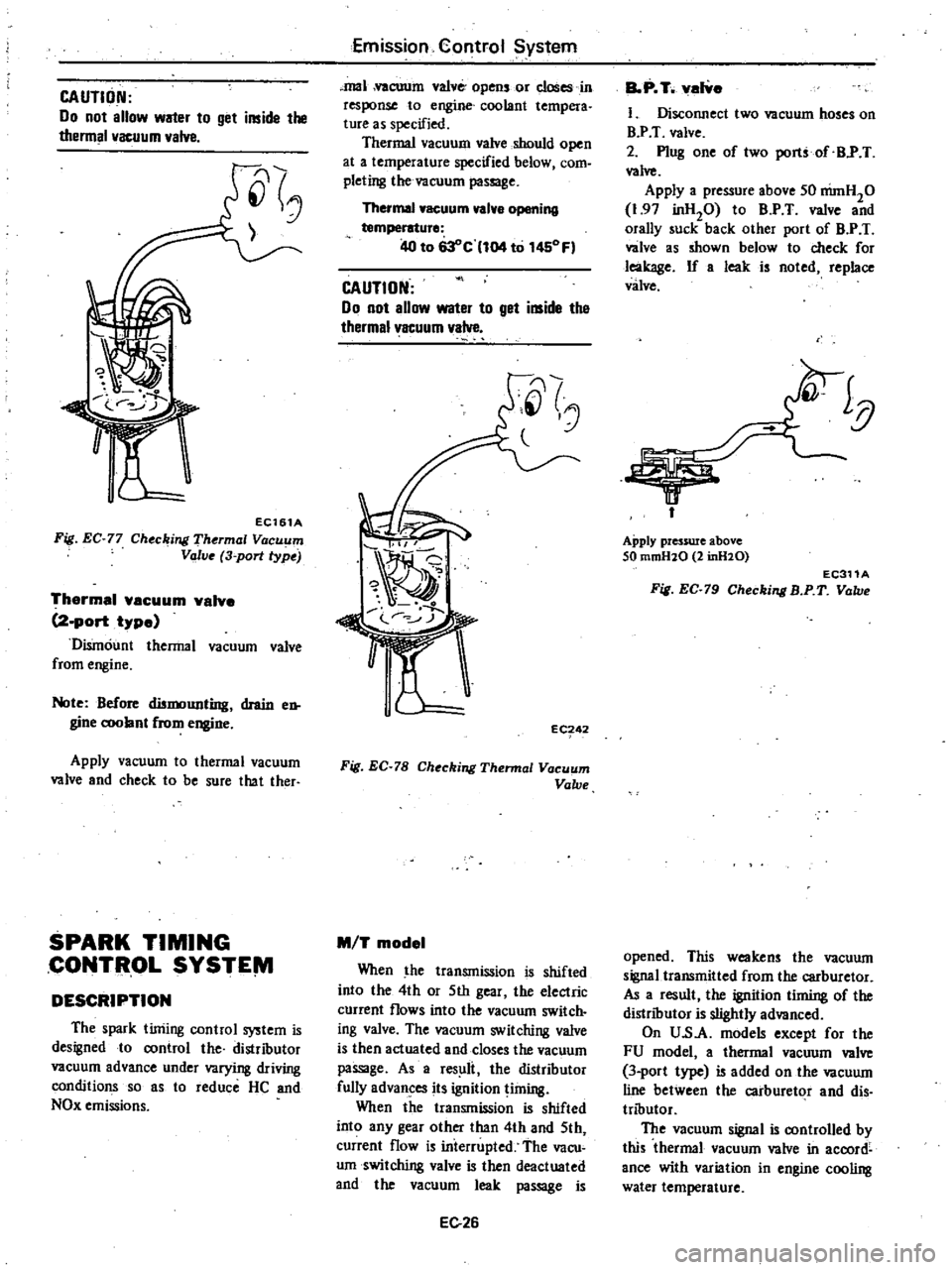
CAUTION
Do
not
allow
water
to
get
inside
the
thermal
vacuum
valve
EC161A
Fig
EC
77
Ch
c
jng
Th
rmal
Vacuum
Valve
3
port
type
Thermal
vacuum
valve
2
port
type
Dismount
thermal
vacuum
valve
from
engine
Note
Before
dismounting
drain
en
gine
c
oolant
from
engine
Apply
vacuum
to
thermal
vacuum
valve
and
check
to
be
sure
that
ther
SPARK
TIMING
CONTflOL
SYSTE
VI
DESCRIPTION
The
spark
timing
control
system
is
designed
to
control
the
distributor
vacuum
advance
under
varying
driving
conditions
so
as
to
reduce
He
and
NOx
emissions
Emission
Control
System
mal
vacuum
valve
opens
or
closes
in
response
to
engine
coolant
tempera
ture
as
specified
Thermal
vacuum
valve
should
open
at
a
temperature
specified
below
com
pleting
the
vacuum
passage
Thermal
vacuum
valve
opening
temperature
40
to
63
c
104
to
1450
Fl
CAUTION
00
not
allow
water
to
get
inside
the
thermal1
acuum
valve
Jl
i
g
J
eC
42
Fig
EC
78
Ch
ckjng
Thermal
Vacuum
Valve
M
T
model
When
the
transmission
is
shifted
into
the
4th
or
5th
gear
the
electric
current
flows
into
the
vacuum
switch
ing
valve
The
vacuum
switching
valve
is
then
actuated
and
close
the
vacuum
passage
As
a
res
li
the
distributor
fully
advances
its
ignition
liming
When
the
transmission
is
shifted
into
any
gear
other
than
4th
and
5th
current
flow
is
interrupted
The
vacu
umswitclting
valve
is
then
deactuated
and
the
vacuum
leak
passage
is
E026
BoP
T
valve
1
DiSCOIUlect
two
vacuum
hoses
on
BY
T
valve
2
Plug
one
of
two
port
of
BY
T
valve
Apply
a
pressure
above
SO
nimH20
1
97
inHP
to
B
P
T
valve
and
orally
suck
back
other
port
of
B
P
T
valve
as
shown
below
to
check
for
leakage
If
a
leak
is
noted
replace
valve
Apply
pressure
above
SO
mmH10
2
inH10
EC311A
Fig
EC
79
Checking
B
P
T
Valve
opened
This
weakens
the
vacuum
signaUransmitted
from
the
carburetor
As
a
result
the
ignition
timing
of
the
distributor
is
slightly
advanced
On
U
s
A
models
except
for
the
FU
model
a
thermal
vacuum
valve
3
port
type
is
added
on
the
vacuum
line
between
the
carburetor
and
dis
tributor
The
vacuum
signal
is
controlled
by
this
thermal
vacuum
valve
in
accord
ance
with
variation
in
engine
cooling
water
temperature
Page 339 of 548
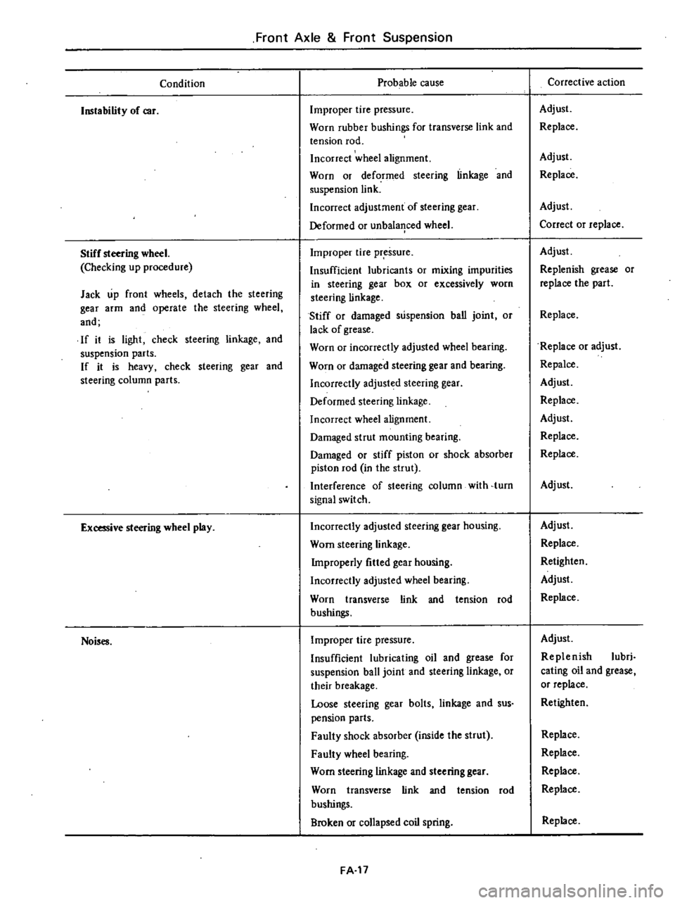
Front
Axle
Front
Suspension
Condition
Instability
of
car
Stiff
steering
wheel
Checking
up
procedure
Jack
up
front
wheels
detach
the
steering
gear
arm
and
operate
the
steering
wheel
and
If
it
is
light
check
steering
linkage
and
suspension
parts
If
it
is
heavy
check
steering
gear
and
steering
column
parts
Excessive
steering
wheel
play
Noises
Probable
cause
Improper
tire
pressure
Worn
rubber
bushings
for
transverse
link
and
tension
rod
Incorrect
wheel
alignment
Worn
or
deformed
steering
linkage
and
suspension
link
Incorrect
adjustment
of
steering
gear
Deformed
or
unbala
1ced
wheel
Improper
tire
pressure
Insufficient
lubricants
or
mixing
impurities
in
steering
gear
box
or
excessively
worn
steering
linkage
Stiff
or
damaged
suspension
ban
joint
or
lack
of
grease
Worn
or
incorrectly
adjusted
wheel
bearing
Worn
or
damaged
steering
gear
and
bearing
Incorrectly
adjusted
steering
gear
Deformed
steering
linkage
Incorrect
wheel
alignment
Damaged
strut
mounting
bearing
Damaged
or
stiff
piston
or
shock
absorber
piston
rod
in
the
strut
Interference
of
steering
column
with
turn
signal
switch
Incorrectly
adjusted
steering
gear
housing
Worn
steering
linkage
Improperly
fitted
gear
housing
Incorrectly
adjusted
wheel
bearing
Worn
transverse
link
and
tension
rod
bushings
Improper
tire
pressure
Insufficient
lubricating
oil
and
grease
for
suspension
ball
joint
and
steering
linkage
or
their
breakage
Loose
steering
gear
bolts
linkage
and
sus
pension
parts
Faulty
shock
absorber
inside
the
strut
Faulty
wheel
bearing
Worn
steering
linkage
and
steering
gear
Worn
transverse
link
and
tension
rod
bushings
Broken
or
collapsed
coil
spring
FA
17
Corrective
action
Adjust
Replace
Adjust
Replace
Adjust
Correct
or
replace
Adjust
Replenish
grease
or
replace
the
part
Replace
Replace
or
adjust
Repalce
Adjust
Replace
Adjust
Replace
Replace
Adjust
Adjust
Replace
Retighten
Adjust
Replace
Adjust
Replenish
lubri
cating
oil
and
grease
or
replace
Retighten
Replace
Replace
Replace
Replace
Replace
Page 441 of 548
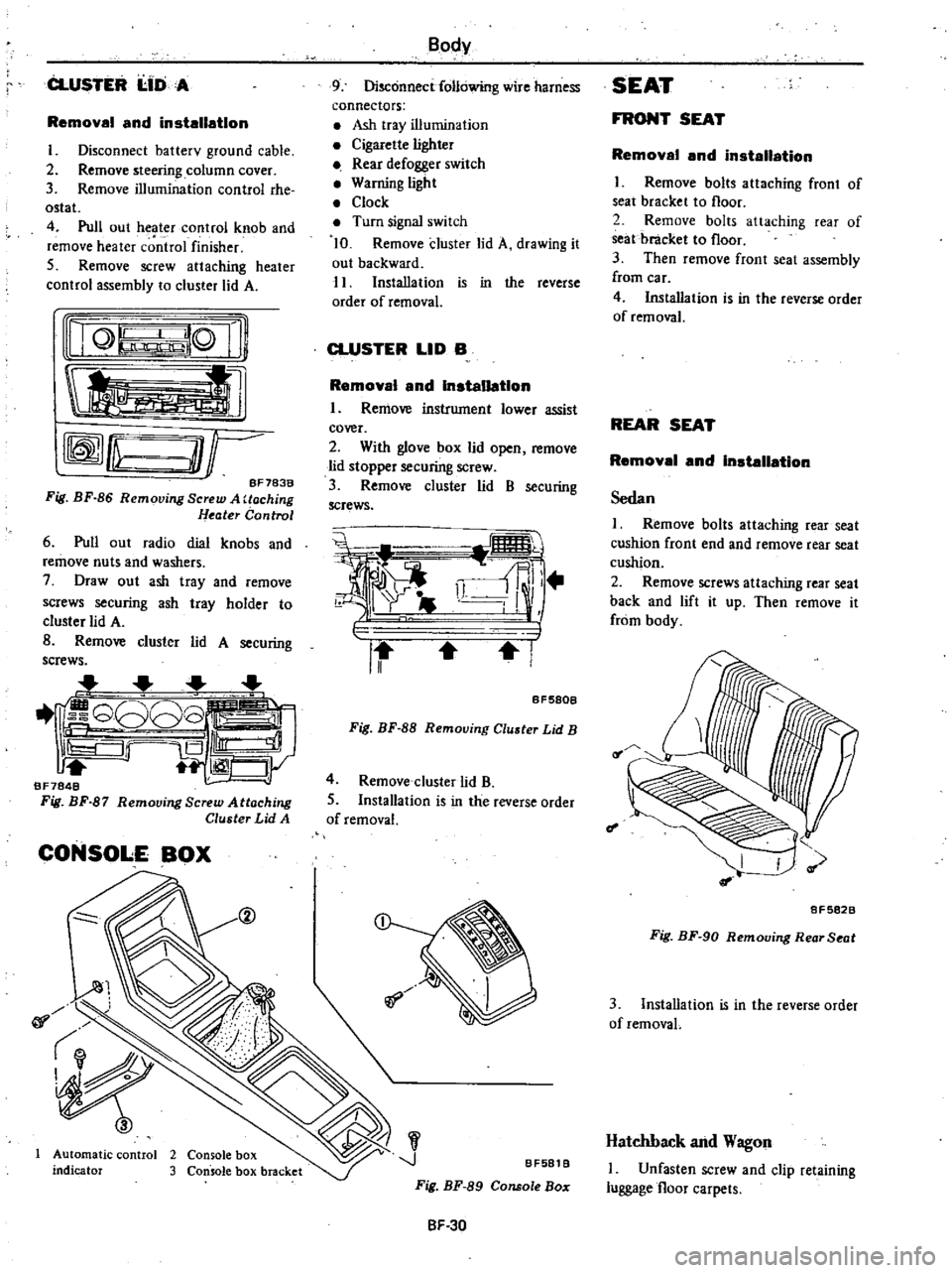
CLUSTER
I
IDA
Removal
and
installation
I
Disconnect
batterv
ground
cable
2
Remove
steering
column
cover
3
Remove
illumination
control
rhe
ostat
4
Pull
out
heater
control
knob
and
remove
heater
c
ntrol
finisher
5
Remove
screw
attaching
heater
control
assembly
to
cluster
lid
A
nQ
lQ
Ii
tl
rffmfLu
O
r
BF783B
Fig
BF
86
Removing
Screw
A
Uoching
Heater
Control
6
Pull
out
radio
dial
knobs
and
remove
nuts
and
washers
7
Draw
out
ash
tray
and
remove
screws
securing
ash
tray
holder
to
cluster
lid
A
B
Remove
cluster
lid
A
securing
screws
1
G808
iS
Ill
1
CJy
BF7848
Fig
BF
87
Remooing
Screw
Attaching
Cluster
Lid
A
CONSOLE
BOX
@
01
Automatic
control
2
Console
box
indicator
3
Console
box
bracket
Body
9
Disconnect
following
wire
harness
connectors
Ash
tray
illumination
Cigarette
lighter
Rear
defogger
switch
Warning
light
Clock
Turn
signal
switch
10
Remove
cluster
lid
A
drawing
it
out
backward
11
Installation
is
in
the
reverse
order
of
removal
CLUSTER
LID
B
Removal
and
Installation
I
Remove
instrument
lower
assist
cover
2
With
glove
box
lid
open
remove
lid
stopper
securing
screw
3
Remove
cluster
lid
B
securing
screws
i
i
ll
r
II
I
BF580B
Fig
BF
88
Removing
Cluster
Lid
B
4
Remove
cluster
lid
B
5
Installation
is
in
the
reverse
order
of
removal
J
BF581
B
Fig
BF
89
Console
Bo
SF
30
SEAT
FRONT
SEAT
Removal
and
installation
I
Remove
bolts
attaching
front
of
seat
bracket
to
floor
2
Remove
bolts
attaching
rear
of
seat
bracket
to
floor
3
Then
remove
front
seat
assembly
from
car
4
Installation
is
in
the
reverse
order
of
removal
REAR
SEAT
Removal
and
Installation
Sedan
I
Remove
bolts
attaching
rear
seat
cushion
front
end
and
remove
rear
seat
cushion
2
Remove
screws
attaching
rear
seat
back
and
lift
it
up
Then
remove
it
from
body
f
I
8F5828
Fig
BF
90
Removing
Rear
Seat
3
Installation
is
in
the
reverse
order
of
removaL
Hatchback
and
Wagon
I
Unfasten
screw
and
clip
retaining
luggage
floor
carpets
Page 446 of 548
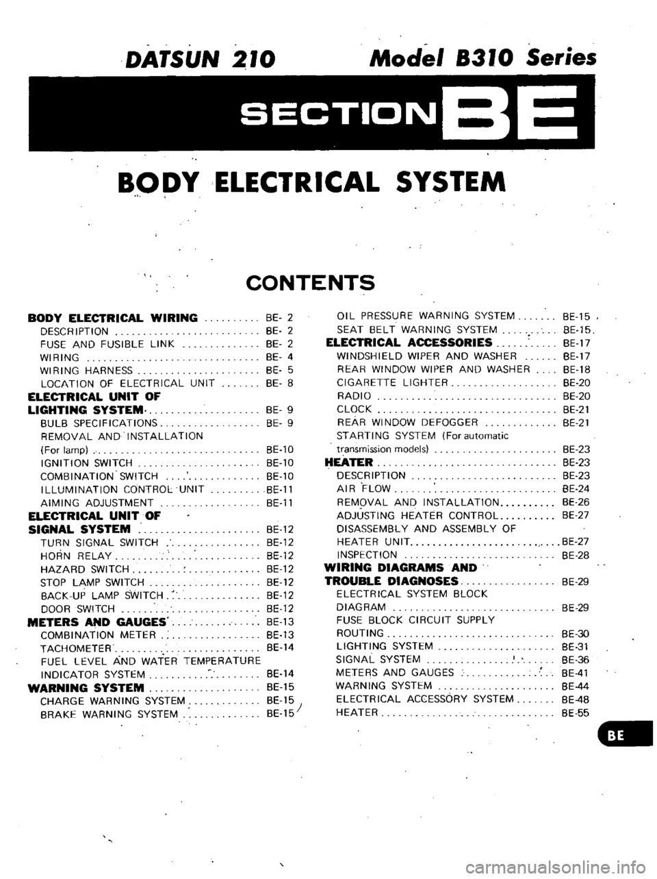
DATSUN
210
Model
8310
Series
SECTIONBE
BODY
ELECTRICAL
SYSTEM
CONTENTS
BODY
ELECTRICAL
WIRING
DESCRIPTION
FUSE
AND
FUSIBLE
LINK
WIRING
WIRING
HARNESS
LOCATION
OF
ELECTRICAL
UNIT
ELECTRICAL
UNIT
OF
LIGHTING
SYSTEM
BULB
SPECIFICATIONS
REMOVAL
AND
INSTALLATION
For
lamp
IGNITION
SWITCH
COMBINATION
SWITCH
ILLUMINATION
CONTROL
UNIT
AIMING
ADJUSTMENT
ELECTRICAL
UNIT
OF
SIGNAL
SYSTEM
BE
12
TURN
SIGNAL
SWITCH
BE
12
HORN
RELAY
BE
12
HAZARD
SWITCH
BE
12
STOP
LAMP
SWITCH
BE
12
BACK
UP
LAMP
SWITCH
BE
12
DOOR
SWITCH
BE
12
METERS
AND
GAUGES
BE
13
COMBINATION
METER
BE
13
TACHOMETER
BE
14
FUEL
LEVEL
AND
WATER
TEMPERATURE
INDICATOR
SYSTEM
BE
14
WARNING
SYSTEM
BE
15
CHARGE
WARNING
SYSTEM
BE
15
BRAKE
WARNING
SYSTEM
BE
15
BE
2
BE
2
BE
2
BE
4
BE
5
BE
8
BE
9
BE
9
BE
10
BE
10
BE
10
BE
11
BE
11
OIL
PRESSURE
WARNING
SYSTEM
SEAT
BELT
WARNING
SYSTEM
ELECTRICAL
ACCESSORIES
WINDSHIELD
WIPER
AND
WASHER
REAR
WINDOW
WIPER
AND
WASHER
CIGARETTE
LIGHTER
RADIO
CLOCK
REAR
WINDOW
DEFOGGER
STARTING
SYSTEM
For
automatic
transmission
models
HEATER
DESCRIPTION
AIR
FLOW
REMOVAL
AND
INSTALLATION
ADJUSTING
HEATER
CONTROL
DISASSEMBLY
AND
ASSEMBLY
OF
HEATER
UNIT
INSPECTION
WIRING
DIAGRAMS
AND
TROUBLE
DIAGNOSES
ELECTRICAL
SYSTEM
BLOCK
DIAGRAM
FUSE
BLOCK
CIRCUIT
SUPPLY
ROUTING
LIGHTING
SYSTEM
SIGNAL
SYSTEM
METERS
AND
GAUGES
WARNING
SYSTEM
ELECTRICAL
ACCESSORY
SYSTEM
HEATER
BE
15
BE
15
BE
17
BE
17
BE
18
BE
20
BE
20
BE
21
BE
21
BE
23
BE
23
BE
23
BE
24
BE
26
BE
27
BE
27
BE
28
BE
29
BE
29
BE
30
BE
31
BE
36
BE
41
BE
44
BE
4B
BE
55
Page 447 of 548
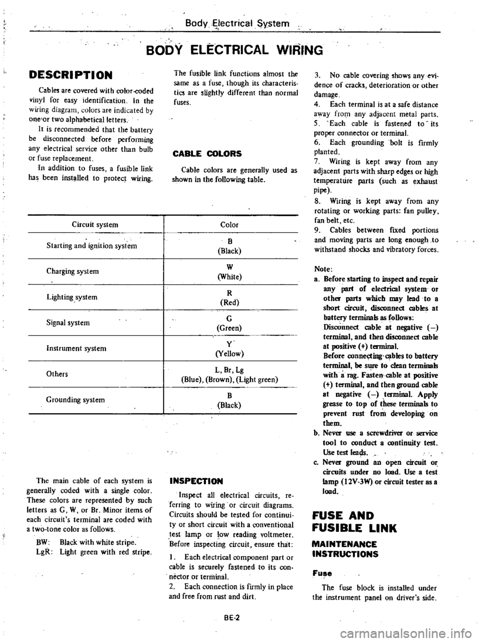
DESCRI
PTI
ON
Cabl
are
covered
with
color
coded
vinyl
for
easy
identification
In
the
wiring
diagram
olors
are
indicated
by
one
or
two
alphabetical
letters
It
is
recommended
that
the
battery
be
disconnected
before
performing
any
electrical
service
other
than
bulb
or
fuse
replacement
In
addition
to
fuses
a
fusible
link
has
been
installed
to
protect
wiring
Circuit
system
Starting
and
ignition
system
Charging
system
Lighting
system
Signal
system
Instrument
system
Others
Grounding
system
The
main
cable
of
each
system
is
generally
coded
with
a
single
color
These
colors
are
represented
by
such
letters
as
G
W
or
Br
Minor
items
of
each
circuit
s
terminal
are
coded
with
a
two
tone
color
as
follows
BW
Black
with
white
stripe
LgR
Light
green
with
red
stripe
Body
ectrical
System
BODY
ELECTRICAL
WIRING
The
fusible
link
functions
almost
the
same
as
a
fuse
though
its
characteris
tics
are
slightly
different
than
normal
fuses
CABLE
COLORS
Cable
colors
are
generally
used
as
shown
in
the
following
table
Color
B
Black
W
White
R
Red
G
Green
y
Yellow
L
Br
Lg
Blue
Brown
Light
green
B
Black
INSPECTION
Inspect
all
electrical
circuits
Ie
Terring
to
wiring
or
circuit
diagrams
Circuits
should
be
tested
for
continui
ty
or
short
circuit
with
a
conventional
test
lamp
or
low
reading
voltmeter
Before
inspecting
circuit
ensure
that
I
Each
electrical
component
part
or
cable
is
securely
fastened
to
its
con
nector
or
tenninal
2
Each
connection
is
fIrmly
in
place
and
free
from
rust
and
dirt
BE
2
3
No
cable
covering
shows
any
evi
dence
of
cracks
deterioration
or
other
damage
4
Each
terminal
is
at
a
safe
distance
3
Vay
from
any
adjacent
metal
parts
5
Each
cable
is
fastened
to
its
proper
connector
or
terminal
6
Each
grounding
bolt
is
fumly
planted
7
Wiring
is
kept
away
from
any
adjacent
parts
with
sharp
edges
or
high
temperature
parts
such
as
exhaust
pipe
8
Wiring
is
kept
away
from
any
rotating
or
working
parts
fan
pulley
fan
belt
etc
9
Cables
between
fIXed
portions
and
moving
parts
are
long
enough
to
withstand
shocks
and
vibratory
forces
Note
a
Before
starting
to
inspect
and
repair
any
part
of
electrical
system
or
oth
parts
which
may
lead
to
a
short
circuit
disconnect
cables
at
battery
terminals
as
follows
Disconnect
cable
at
negative
terminal
and
then
disconnect
cable
at
positive
terminal
Before
connecting
cables
to
battery
terminal
be
s
1
to
clean
tenninals
with
a
rag
Fasten
cable
at
positive
t
minal
and
then
ground
cable
at
negative
tenninal
Apply
grease
to
top
of
these
terminals
to
prevent
rust
from
developing
on
them
b
Ne
use
a
screwdriver
or
service
tool
to
oonduct
a
oontinuity
test
Use
test
leads
Co
Nev
ground
an
open
circuit
or
circuits
under
no
lood
Use
a
test
lamp
I2V
3W
or
circuit
tester
as
a
lood
FUSE
AND
FUSIBLE
LINK
MAINTENANCE
INSTRUCTIONS
Fuse
The
fuse
block
is
installed
under
the
instrument
panel
on
driver
s
side
Page 450 of 548
m
c
n
to
l
l
I
g
iF
0
1
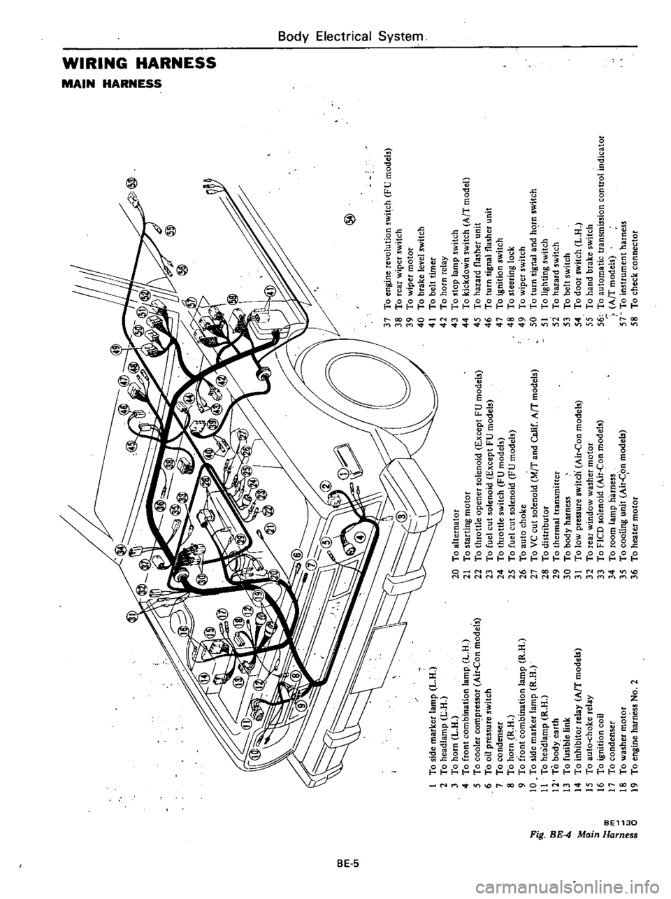
To
side
marker
lamp
L
H
2
To
headlamp
L
H
3
To
horn
L
H
4
To
front
combination
lamp
L
H
5
To
cooler
co
pressor
Air
Con
models
6
To
oil
pressure
switch
7
To
condenser
8
To
horn
R
H
9
To
front
combination
la
t11p
R
H
10
To
side
marker
lamp
R
H
11
To
headlamp
R
H
12
To
body
earth
13
To
fusible
link
14
To
inhibitor
relay
AfT
model
15
To
aut6
choke
relay
16
To
ignition
coil
17
To
condenser
18
To
washer
motor
19
To
engine
harness
No
2
@
20
To
alternator
21
To
starting
motor
22
To
throttle
opener
solenoid
Except
FU
models
23
To
fuel
cut
solenoid
Except
FU
models
24
To
throttle
switch
FU
models
25
To
fuel
cut
solenoid
FU
models
26
To
auto
choke
27
To
VC
cut
solenoid
M
T
and
Calif
AfT
models
28
To
distributor
29
To
thermal
transmitter
30
To
body
harness
31
To
low
pressure
switcn
Air
Con
models
32
To
rear
window
washer
motor
33
To
FICO
solenoid
Air
Con
models
34
To
room
lamp
harness
35
To
cooling
unit
Air
C
on
models
36
To
heater
motor
37
To
engine
revolution
switch
FU
models
38
To
rear
wiper
switch
39
To
wiper
motor
40
To
brake
level
switch
41
To
belt
timer
42
To
horn
relay
43
To
stop
lamp
switch
44
To
kickdown
switch
AfT
model
45
To
hazard
flasher
unit
46
To
turn
signal
flasher
unit
47
To
ignition
switch
48
To
steering
lock
49
To
wiper
switch
50
To
turn
signal
and
hC
rn
switch
51
To
lighting
switch
5i
To
hazard
switch
53
To
belt
switch
54
To
door
switch
L
H
55
To
hand
brake
switch
56
To
automatic
transmission
control
indicator
AfT
models
57
To
instrument
harness
58
To
check
connector
I
0
i
a
z
Z
G
z
tIl
tIl
a
Z
Il
I
to
o
Co
m
16
n
n
OJ
1
3
Page 454 of 548
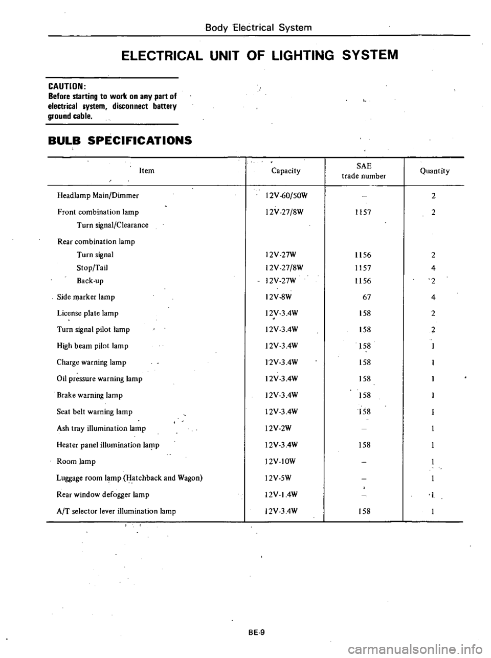
Body
Electrical
System
ELECTRICAL
UNIT
OF
LIGHTING
SYSTEM
CAUTION
Before
starting
to
work
on
any
part
of
electrical
system
disconnect
battery
ground
cable
BULB
SPECIFICATIONS
Item
Headlamp
Main
Dilnmer
Front
combination
lamp
Turn
signal
Clearance
Rear
combination
lamp
Turn
signal
Stop
Tail
Back
up
Side
marker
lamp
License
plate
lamp
Turn
signal
pilot
lamp
High
beam
pilot
lamp
Charge
warning
lamp
Oil
pressure
warning
lamp
Brake
warning
lamp
Seat
belt
warning
lamp
Ash
tray
illumination
lamp
Heater
panel
illumination
laf
lp
Room
lamp
Luggage
room
lamp
Hatchback
and
Wagon
Rear
window
defogger
lamp
AfT
selector
lever
illumination
lamp
Capacity
SAE
trade
number
12V
60
50W
l2V
27
8W
1157
l2V
27W
12V
27
8W
12V
27W
12V
8W
l2V
3
4W
l2V
3
4W
l2V
3
4W
12V
3
4W
12V
3
4W
12V
3
4W
12V
3
4W
l2V2W
l2V
3
4W
l2V
lOW
Quantity
2
2
1156
2
1157
4
1156
2
67
4
158
2
158
2
158
158
158
158
158
158
l2V
5W
12V
14W
12V
3
4W
158
BE
9
Page 455 of 548
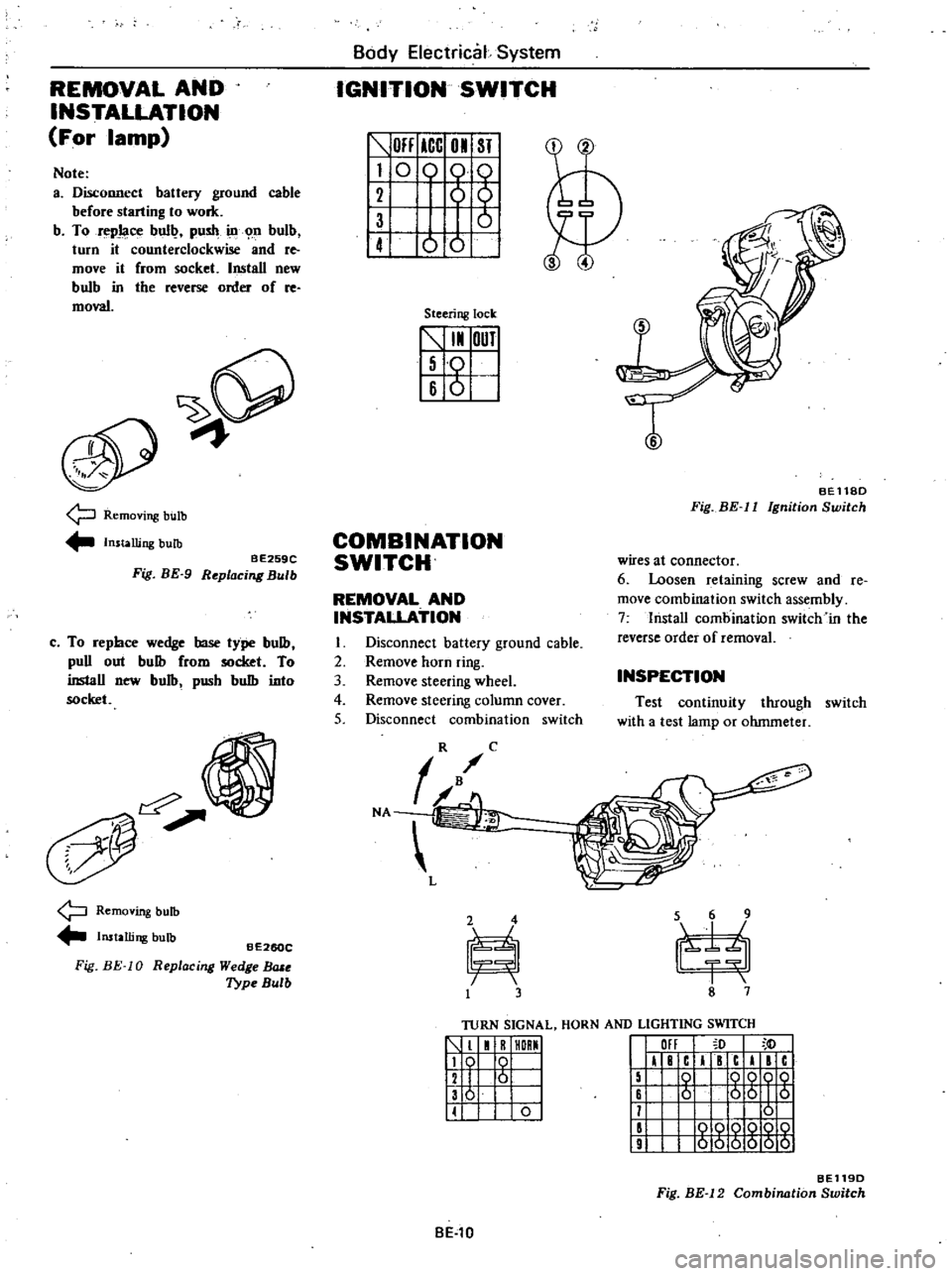
REMOVAL
AND
INSTALLATION
For
lamp
Note
a
Disconnect
battery
ground
cable
before
starting
to
work
b
To
repJaoe
bull
push
ill
n
bulb
turn
it
counterclockwise
and
re
move
it
from
socket
Install
new
bulb
in
tbe
reverse
order
of
re
moval
9
Removing
bulb
Installing
bulb
BE259C
Fig
BE
9
Replacing
Bulb
c
To
repbce
wedge
base
type
bulb
puD
out
bulb
from
socket
To
inslaD
new
bulb
pusb
bulb
into
socket
Removing
bulb
Installing
bulb
Fig
BE
10
BE260C
R
eplac
ing
Wedge
BlUe
Type
Bulb
Body
Electrical
System
IGNITION
SWITCH
OFF
ICC
01
ST
I
0
0
61
1
ot
Steering
lock
5
I
OUT
I
Iso
16
6
I
T
BEll8D
Fig
BE
II
Ignition
Switch
COMBINATION
SWITCH
wires
at
connector
6
Loosen
retaining
screw
and
Ie
move
combination
switch
assembly
7
lnstaD
combination
switch
in
the
reverse
order
of
removal
REMOVAL
AND
INSTALLATION
I
Disconnect
battery
ground
cable
2
Remove
horn
ring
3
Remove
steering
wheel
4
Remove
steering
column
cover
5
Disconnect
combination
switch
INSPECTION
Test
continuity
through
switch
with
a
test
lamp
or
ohmmeter
TURN
SIGNAL
HORN
AND
LIGHTING
SWITCH
1
1
R
HORMI
119
0
I
12
I
6
I
136
I
II
0
I
III
I
F
c
I
c
I
c
15
0
QQOQ
16
6
56
I
5
11
0
II
000Q
10
9
000000
BE119D
Fig
BE
12
Combination
Switch
BE
l0
Page 463 of 548
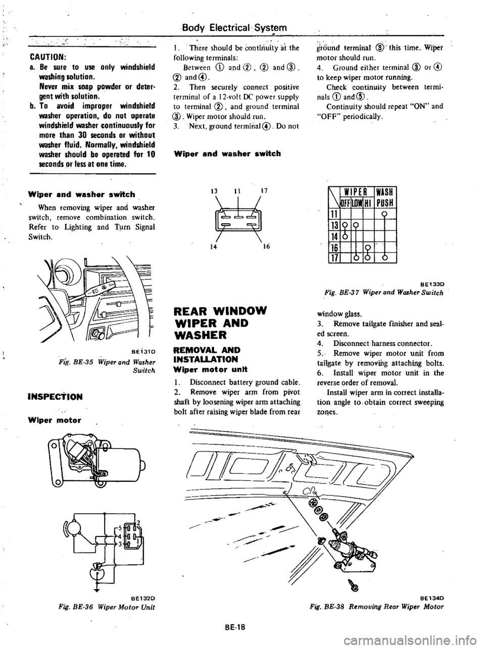
CAUTION
a
Be
sure
to
use
only
windshield
washing
solution
Never
mix
soap
powder
or
deter
gent
with
solution
b
To
avoid
improper
windshield
washer
operation
do
not
operate
windshield
washer
continuously
for
more
than
30
seconds
or
without
washer
fluid
Normally
windshield
washer
should
be
operated
for
10
seconds
or
less
at
one
time
Wiper
and
washer
switch
When
removing
wiper
and
washer
switch
remove
combination
switch
Refer
to
Lighting
and
Turn
Signal
Switch
BE131D
Fig
BE
35
Wiper
and
Wll5her
Switch
INSPEctiON
Wiper
motor
W
P
6
LJ
3
B
gu
BE132D
Fig
BE
36
Wiper
Motor
Unit
Body
Electrical
Sys
em
I
There
should
be
continuity
at
the
following
terminals
Between
ill
and
@
@
and
CID
@
and@
2
Then
securely
connect
positive
terminal
of
a
2
volt
DC
power
supply
to
terminal
@
and
ground
terminal
CID
Wiper
motor
should
run
3
Next
ground
terminal@
Do
not
Wiper
and
washer
switch
t3
11
17
I
7b
14
16
REAR
WINDOW
WIPER
AND
WASHER
REMOVAL
AND
INSTALLATION
Wiper
motor
unit
Disconnect
battery
ground
cable
2
Remove
wiper
arm
from
pivot
shaft
by
loosening
wiper
arm
attaching
bolt
after
raising
wiper
blade
from
rear
o
i
Jill
BE1B
ground
terminal
CID
this
time
Wiper
motor
should
run
4
Ground
either
terminal
CID
or
@
to
keep
wiper
motor
running
Chec
k
continuity
between
termi
nals
ill
and@
Continuity
should
repeat
ON
and
OFF
periodically
W
PE
I
WASH
DFF
lOW
HI
PUSH
11
0
116
117
o
g
b
BE1330
Fig
BE
37
Wiper
and
WcuherSwitch
window
glass
3
Remove
tailgate
finisher
and
seal
ed
screen
4
Disconnect
harness
connector
5
Remove
wiper
motor
unit
from
tailgate
by
removiDg
attaching
bolts
6
Install
wiper
motor
unit
in
the
reverse
order
of
removal
Install
wiper
arm
in
correct
installa
tion
angle
to
obtain
correct
sweeping
wQes
BE134D
Fig
BE
38
Removing
Rear
Wiper
Motor