fuse DATSUN 210 1979 Service Manual
[x] Cancel search | Manufacturer: DATSUN, Model Year: 1979, Model line: 210, Model: DATSUN 210 1979Pages: 548, PDF Size: 28.66 MB
Page 104 of 548
1
Ignition
switch
2
Amplifier
3
Speed
switch
Note
a
Tightening
torque
is
1
8
to
2
2
kg
m
13
to
16
ft
Ib
b
After
replacement
start
engine
and
check
to
be
sure
that
fuel
is
not
leaking
and
that
anti
dieseling
sole
noid
i
in
good
condition
EFOSOA
Fig
EF47
Checking
Anti
dieaeling
Solenoid
l
SJ
Engine
Fuel
THROTTLE
OPENER
CONTROL
SYSTEM
When
idling
speed
is
too
high
and
does
not
drop
to
idling
speed
the
throttle
opener
control
system
should
be
checked
Manual
transmission
models
I
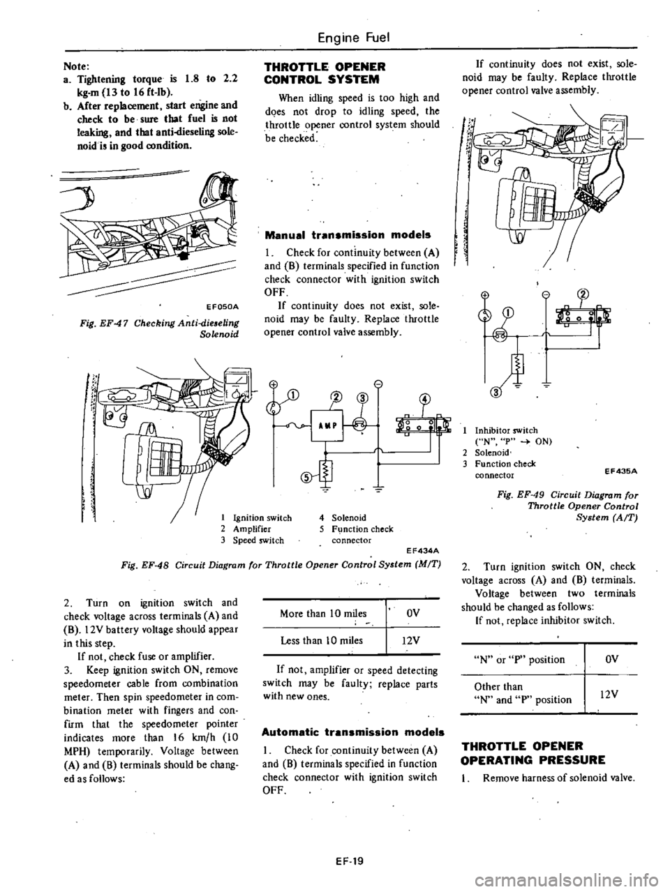
Check
for
continuity
between
A
and
8
terminals
specified
in
function
check
connector
with
ignition
switch
OFF
If
continuity
does
not
exist
sole
noid
may
be
faulty
Replace
throttle
opener
control
valve
assembly
e
1J
3
o
0
5
4
Solenoid
5
F
nction
check
connector
EF434A
Fig
EF
48
Circuit
Diagram
for
Throttle
Opener
Control
System
MIT
2
Turn
on
ignition
switch
and
check
voltage
across
terminals
A
and
8
l2V
battery
voltage
should
appear
in
this
step
If
not
check
fuse
or
amplifier
3
Keep
ignition
switch
ON
remove
speedometer
cable
from
combination
meter
Then
spin
speedometer
in
com
bination
meter
with
fingers
and
con
firm
that
the
speedometer
pointer
indicates
more
than
16
km
h
10
MPH
temporarily
Voltage
between
A
and
8
terminals
should
be
chang
ed
as
follows
More
than
10
miles
OV
Less
than
10
miles
12V
If
not
amplifier
or
speed
detecting
switch
may
be
faulty
replace
parts
with
new
ones
Automatic
transmission
models
I
Check
for
continuity
between
A
and
8
terminals
specified
in
function
check
connector
with
ignition
switch
OFF
EF
19
If
continuity
does
not
exist
sole
noid
may
be
faulty
Replace
throttle
opener
control
valve
assembly
If
t
r
If
I
Inhibitor
switch
N
p
ON
2
Solenoid
3
Function
check
connector
EF43SA
Fig
EF
49
Circuit
Diagram
for
Throttle
Opener
Control
System
AfT
2
Turn
ignition
switch
ON
check
voltage
across
A
and
8
terminals
Voltage
between
two
terminals
should
be
changed
as
follows
If
not
replace
inhibitor
switch
N
or
p
position
OV
Other
than
N
and
p
position
l2V
THROTTLE
OPENER
OPERATING
PRESSURE
I
Remove
harness
of
solenoid
valve
Page 107 of 548
1
Servo
diaphragm
4
Stopper
2
Bracket
5
Link
3
Lock
nut
6
Carburetor
EF732
Fig
EF
56
Adjusting
Seroo
Diaphragm
Adjwting
Screw
FUEL
SHUT
OFF
SYSTEM
Precautions
a
Before
checking
make
sure
engine
is
warmed
up
and
choke
wive
is
fully
open
b
On
air
conditioner
equipped
mod
els
turn
off
air
conditioner
switch
in
steps
I
through
12
c
Keep
clutch
pedal
held
down
with
your
foot
while
depressing
accele
g
f
J
1
Engine
Fuel
rator
pedllI
when
shift
leVer
ISm
any
position
other
than
neutral
Otherwise
car
will
surge
forward
abruptly
Note
Do
not
attach
test
leads
of
a
circuit
tester
to
terminals
other
than
those
designated
Run
engine
at
idling
speed
2
Disconnect
anti
dieseling
solenoid
valve
connector
and
make
sure
that
engine
stops
If
not
replace
anti
dieseling
solenoid
valve
assembly
EF856
Fig
EF
57
Checking
Function
of
Anti
die
eling
Solenoid
Valve
31
A
t
CID
@
V
II
l
To
distributor
T
n
l1on
coon
o
1
Ignition
switch
2
Fuse
3
Anti
dieseling
solenoid
4
Neu
tral
detecting
switch
5
Throttle
valve
swltch
6
Engine
revolution
switch
7
Transistor
ignition
unit
8
Function
test
connector
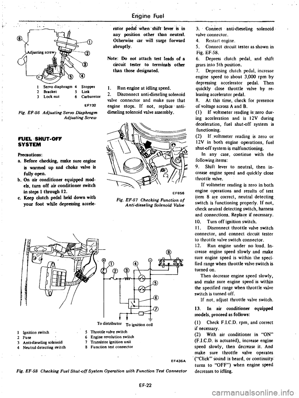
Fig
EF
58
Checking
Fuel
Shut
off
System
Operation
with
Function
Test
Connector
EF436A
EF
22
3
Conilect
anti
ieselingsolenoid
valve
connector
4
Restart
engine
5
Connect
circuit
tester
as
shown
in
Fig
EF
S8
6
Depress
clutch
pedal
and
shift
gears
into
5th
position
7
Depressing
clutch
pedal
increase
engine
speed
to
about
3
000
rpm
by
depressing
accelerator
pedal
Then
quickly
close
throttle
wIve
by
re
leasing
accelerator
pedal
8
At
this
time
check
for
presence
of
voltage
across
A
and
B
I
If
voltmeter
reading
i
ero
dur
ing
acceleration
and
is
12V
during
deceleration
fuel
shut
off
system
is
functioning
2
If
voltmeter
reading
is
zero
or
l2V
in
both
engine
operations
fuel
shut
off
system
is
malfunctioning
In
any
case
continue
with
the
following
items
9
Shift
lever
to
neutral
then
in
crease
engine
speed
and
quickly
close
throttle
valve
If
voltmeter
reading
is
zero
in
both
engine
operations
and
results
of
test
i
tern
8
are
correct
neutral
detecting
switch
is
functioning
properly
If
not
check
neutral
detecting
switch
harness
and
connections
Replace
if
necessary
10
Turn
off
ignition
switch
II
Disconnect
throttle
valve
switch
connector
and
connect
circuit
tester
to
throttle
valve
switch
connector
12
Run
engine
under
no
load
In
crease
engine
speed
slowly
and
make
sure
engine
speed
is
within
the
speci
fied
range
when
throttle
valve
switch
is
turned
on
Then
decrease
engine
speed
slowly
and
make
sure
engine
speed
is
within
the
specified
range
when
throttle
valve
switch
is
turned
off
If
not
adjust
throttle
valve
switch
13
In
air
conditioner
equipped
models
proceed
as
follows
I
Check
F
l
C
D
rpm
and
correct
if
necessary
2
With
air
conditioner
in
ON
F
l
C
D
is
actuated
increase
engine
speed
slowly
then
decrease
it
And
make
sure
throttle
valve
operates
Click
sOund
is
heard
or
continuity
turns
to
OFF
when
engine
speed
decreases
to
idling
Page 133 of 548
DISASSEMBLY
AND
ASSEMBLY
OF
AIR
PUMP
Emission
Control
System
Bearing
kit
Disassembly
I
Remove
pulley
drive
bolts
and
remove
pulley
from
hub
2
Secure
air
pump
drive
hub
in
a
vise
and
remove
end
cover
bolts
CAUTION
Never
clamp
on
the
aluminum
hous
ing
EC302
Fig
EC
30
Removing
Cover
3
Remove
end
cover
by
carefuDy
tapping
around
dowel
pin
wi
th
a
plas
tic
mallet
and
lift
up
straight
Vane
kit
4
Put
match
marks
0
on
rotor
ring
and
side
of
rotor
to
ensure
correct
reassembly
and
remove
screws
that
retain
rotor
ring
to
rotor
using
a
Hexagon
Wrench
STl98l0000
Note
a
Generally
match
marks
are
indi
cated
on
both
rotor
ring
and
rotor
by
the
manufacturer
Ee111
Fig
EC
31
Removing
Rotor
Ring
b
Discard
screws
which
were
re
moved
Always
use
new
ones
when
installing
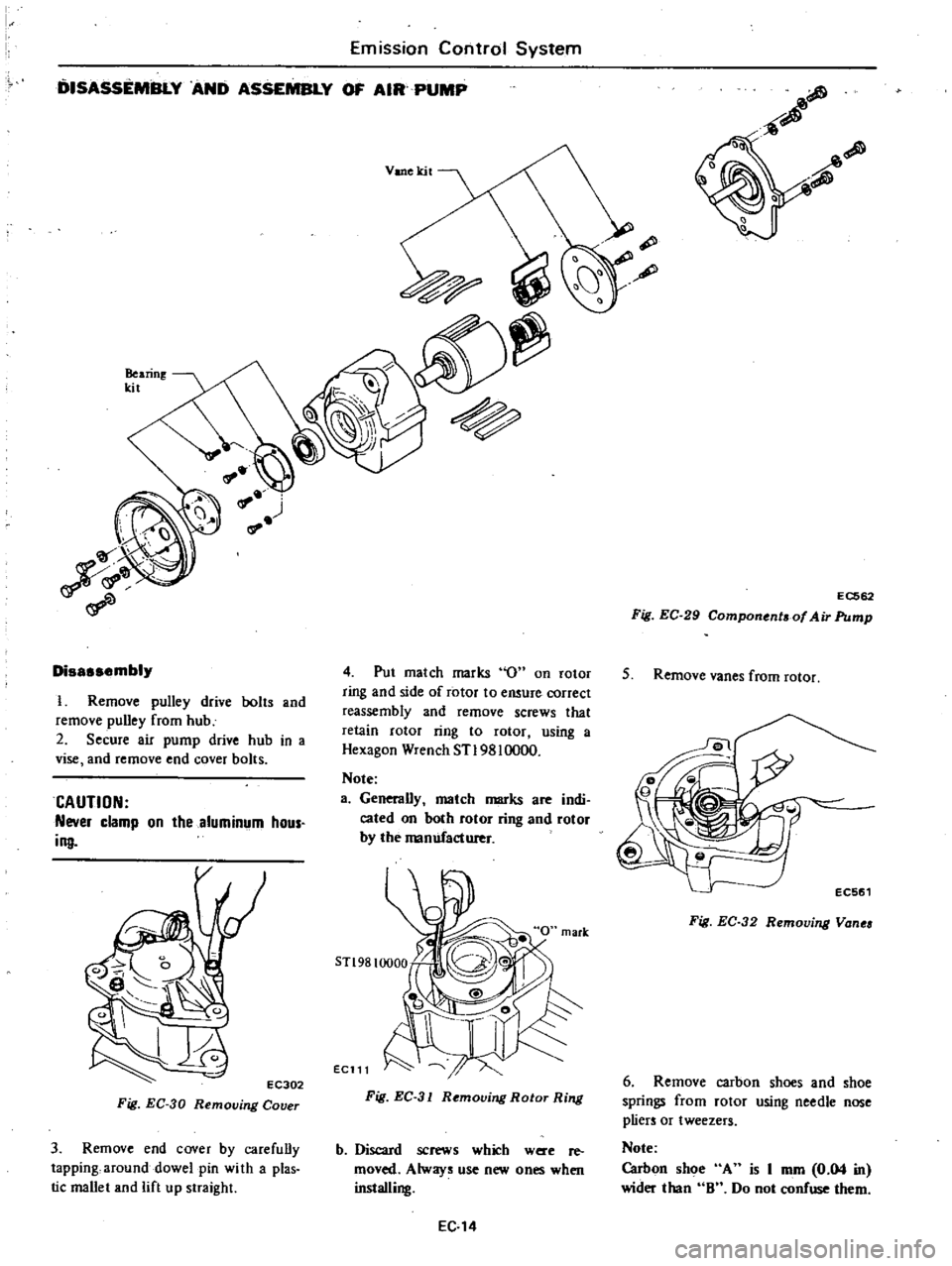
EC
14
EC562
Fig
EC
29
Component
of
Air
Pump
5
Remove
vanes
from
rotor
Fig
EC
32
Removing
Vanea
6
Remove
carbon
shoes
and
shoe
springs
from
rotor
using
needle
nose
pliers
or
tweezers
Note
Carbon
shoe
A
is
I
mm
0
04
in
wider
than
8
Do
not
confuse
them
Page 134 of 548
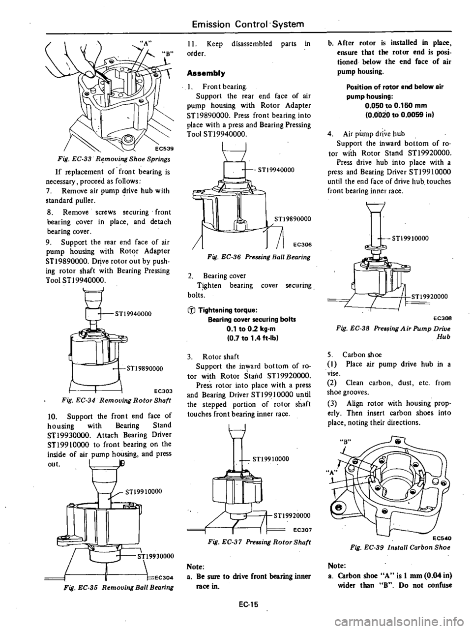
Fig
EC
33
R
moving
Shoe
Springs
If
replacement
of
fron
t
bearing
is
necessary
proceed
as
follows
7
Remove
air
pump
drive
hub
with
standard
puller
8
Remove
screws
securing
front
bearing
cover
in
place
and
detach
bearing
cover
9
Support
the
rear
end
face
of
air
pump
housing
with
Rotor
Adapter
STI
9890000
Drive
rotor
out
by
push
ing
rotor
shaft
with
Bearing
Pressing
Tool
STI
9940000
STl9940000
JJr
STl9890000
EC303
Fig
EC
34
Removing
Rotor
Shaft
10
Support
the
fron
t
end
face
of
housing
with
Bearing
Stand
STI9930000
Attach
Bearing
Driver
STI
9910000
to
front
bearing
on
the
inside
of
air
pump
housing
and
press
out
I
STl9910000
1
c
R
9930000
II
EC304
Fig
EC
35
R
mouing
Ball
B
aring
Emission
Control
System
II
Keep
disassembled
parts
in
order
Assembly
Front
bearing
Support
the
rear
end
face
of
air
pump
housing
with
Rotor
Adapter
STI
9890000
Press
front
bearing
into
place
with
a
press
and
Bearing
Pressing
Tool
STI
9940000
I
I
J
j
71
EC306
Fig
EC
36
Pre88ing
Ball
Bearing
2
Bearing
cover
T
ighten
bearing
cover
securing
bolts
@
Tightening
torque
Bearing
cover
securing
bolts
0
1
to
02
kg
m
0
7
to
1
4
ft
Ib
3
Rotor
shaft
Support
the
in
ard
bottom
of
ro
tor
with
Rotor
Staild
STI
9920000
Press
rotor
into
place
with
a
press
and
Bearing
Driver
STI9910000
until
the
stepped
portion
of
rotor
shaft
touches
front
bearing
inner
race
t
7
STl9910000
STl9920000
i
I
EC307
Fig
EC
37
Pressing
Rotor
Shaft
Note
a
Be
sure
to
drive
front
bearing
inner
race
in
EC
15
b
After
rotor
is
installed
in
place
ensure
that
the
rotor
end
is
posi
tioned
helow
the
end
face
of
air
pump
housing
Position
of
rotor
end
below
air
pump
housing
0
050
to
0
150
mm
0
0020
to
0
0059
in
4
Air
pump
drive
hub
Support
the
inward
bottom
of
ro
tor
with
Rotor
Stand
STI
9920000
Press
drive
hub
into
place
with
a
press
and
Bearing
Driver
STI99l0000
until
the
end
face
of
drive
hub
touches
front
bearing
inner
race
H
STl99
10000
EC30B
Fig
EC
38
Pre
sing
A
ir
Pump
Drive
Hub
5
Carbon
shoe
I
Place
air
pump
drive
hub
in
a
vise
2
Clean
carbon
dust
etc
from
shoe
grooves
3
Align
rotor
with
housing
prop
erly
Then
insert
carbon
shoes
into
place
noting
their
directions
EC5
0
Fig
EC
39
Install
Carbon
Sho
Note
a
Carbon
sh
A
is
I
mm
0
04
in
wider
than
B
Do
not
confuse
Page 146 of 548
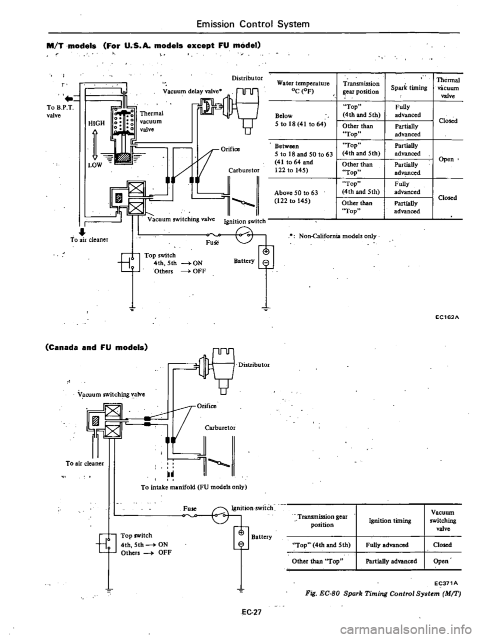
Emission
Control
System
M
T
models
For
U
S
A
models
except
FU
model
Distributor
r
To
B
P
T
valve
HIGH
vacuum
valve
OrifiCO
i
jarburetor
l
Vacuum
switching
valve
Ignition
switch
I
To
air
cleaner
Fuse
8
Top
switch
4th
5th
Others
Battery
8
ON
OFF
Canada
and
FU
models
OM
1orifico
F
JCMburetor
To
air
cleaner
1
V
cuum
switching
valve
To
intake
manifold
FU
models
only
Fuse
G1j
Ignition
switch
Battery
7
EJ
Top
switch
4th
5th
ON
Others
OFF
EC
27
Water
temperature
OC
OF
Below
5
to
18
41
to
64
Between
I
5
to
18
and
50
t063
41
to
64
and
I
122
to
145
I
I
Above
50
to
63
122
to
145
Transmission
ear
position
Top
4th
and
5111
Other
than
Top
Top
4th
and
5th
Other
than
Top
Top
4th
and
5th
Other
than
Top
Non
California
models
only
Thermal
Spark
timing
vacuwn
valve
Fully
advanced
I
Closed
Partially
advanced
Partially
I
advanced
Partially
I
Open
ad
ced
Fully
I
advanced
I
Closed
Partially
advanced
EC162A
Transmission
gear
Vacuwn
Ignition
timing
switching
position
valve
Top
4th
and
5th
Fully
advanced
Closed
Other
than
Top
Partially
advanced
Open
EC371A
Fig
EC
BO
Spork
Timing
Control
Sy
tem
MIT
Page 162 of 548
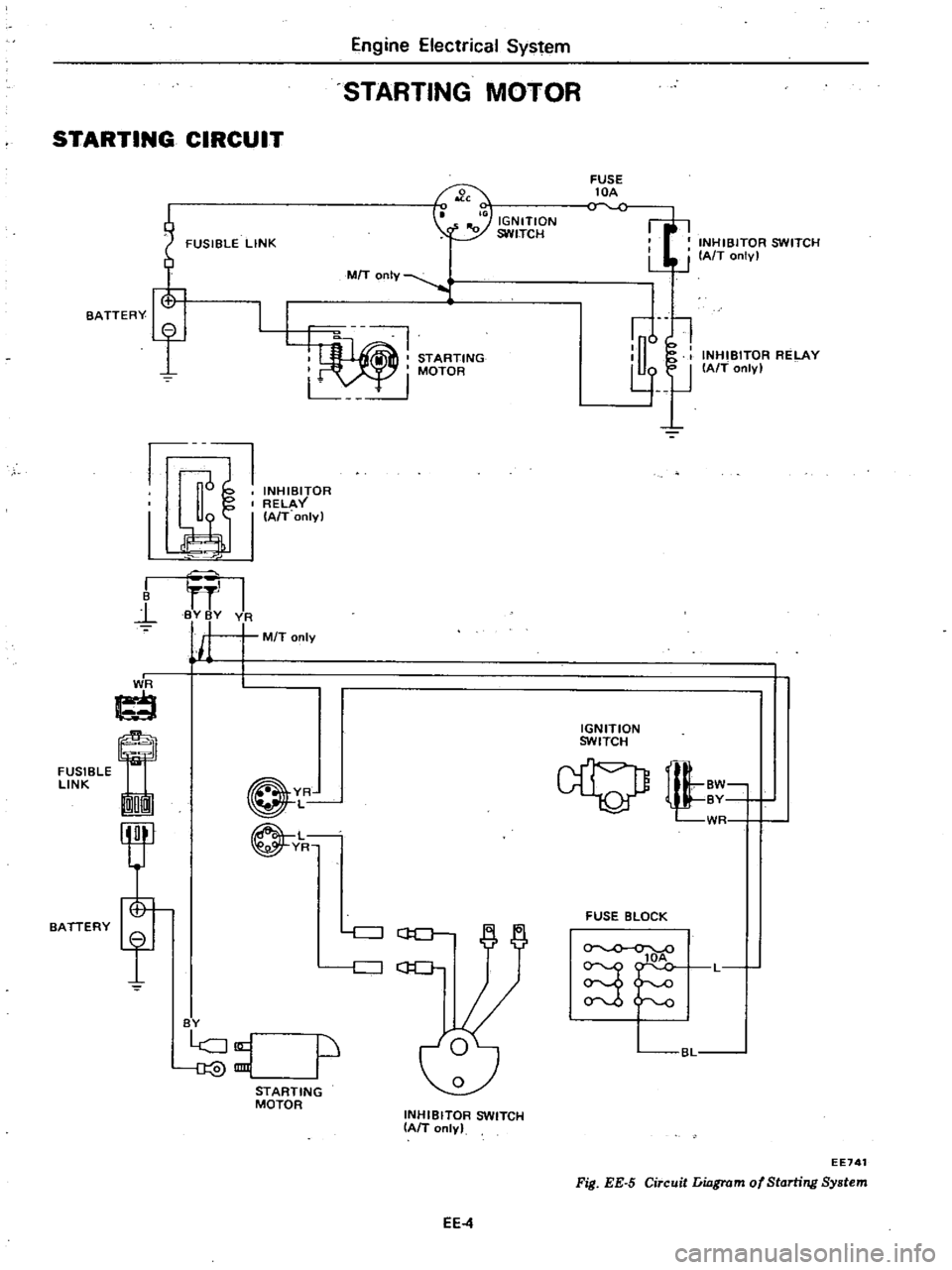
Engine
Electrical
System
STARTING
MOTOR
STARTING
CIRCUIT
FUSIBLE
LINK
FUSE
lOA
INHIBITOR
SWITCH
LJ
J
IAfT
onlv
I
IGNITION
SWITCH
7
MIT
OnIY
STARTING
I
MOTOR
L
u
l
l
lJ
INHIBITOR
RELAY
IAfT
only
BATTERY
f
1J
INHIBITOR
RELAY
I
I
A
T
onlyl
I
B
l
I
BY
BY
VA
j
M
T
only
I
J
ti
FUSIBLE
LINK
On
IGNITION
SWITCH
BATTERY
YR
L
L
YR
tl
WR
FUSE
BLOCK
c
J
GO
c
J
C
lOA
S
L
BY
p
BL
STARTING
MOTOR
INHIBITOR
SWITCH
IAIT
only
EE741
Fig
EE
5
Circuit
Liagrom
of
Starting
System
EE4
Page 170 of 548
FUSIBLE
LINK
FUSIBLE
LINK
f
BATTERY
@@
V
R
@@
G
G
FUSleLE
ImrnI
LI
NK
MTI
I
En
g
n
l
Electrical
Syst
lOl
IGNITION
SWITCH
FUSE
lOA
o
v
FUSE
lOA
C
V
L@@
BAT
f
L
S
BI
I
I
sl
fRO
L
I
I
F
I
EI
i
K
a
ALTERNATOR
lE
Ie
VOLTAGE
REGULATOR
I
I
L
WR
I
1
d
I
t
J
t
IGNITION
WR
SWITCH
BW
U
0
AUTO
CHOKE
RELAY
G
1
WR
J
I
00
00
gg
1
00
VR
1
E
lDID
I
@
O
BAT
mID
W
J
WR
W
FUSE
BLOCK
CHARGE
WARNING
LAMP
5J
BL
Note
@
V
@
California
models
Non
Qilifomo
18
models
FU
models
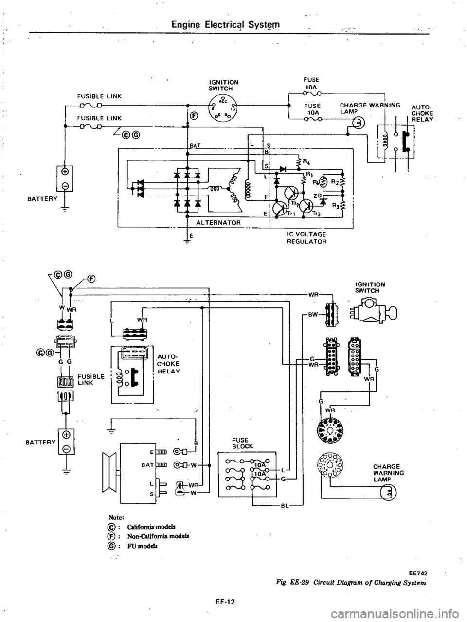
Fig
EE
29
Circuit
Dinrswr
EE742
mofCIuJ
Tg
ng
Sy
t
m
EE
12
Page 201 of 548
INSTALLATION
Install
in
the
reverse
order
of
re
moval
observing
the
following
Note
When
inslal1ing
be
sure
to
check
thaI
electrical
harnesses
are
connected
ly
1
When
installing
first
secure
rear
engine
mounting
member
to
body
2
Refer
to
applicable
section
when
installing
and
adjusting
any
parts
Adjust
clutch
pedal
free
travel
Re
fer
to
Clutch
Pedal
Free
Travel
Section
CL
for
installation
and
adjustment
Adjust
accelerator
control
system
Refer
to
Engine
Control
System
Section
FE
for
adjustment
For
installation
of
air
conditioner
compressor
and
belt
adjustment
Refer
to
Idler
Pulley
and
Com
pressor
Drive
Belt
for
adjustment
of
belt
tension
3
When
installing
exhaust
front
tube
on
exhaust
manifold
be
sure
to
use
new
gasket
4
When
installing
hood
following
engine
installation
be
sure
that
it
is
properly
centered
and
that
hood
lock
operates
securely
Refer
to
Hood
See
tion
BF
for
adjustment
Engine
Removal
Installation
ENGINE
MOUNTING
INSULATOR
FRONT
INSULATOR
Removal
Disconnect
battery
ground
cable
2
Suspend
engine
with
wire
or
chain
3
Remove
front
engine
mounting
insulator
lower
and
upper
nuts
on
both
sides
4
Make
sure
that
wire
or
chain
used
to
suspend
engine
is
positioned
prqper
ly
so
that
no
load
is
applied
to
insulators
and
remove
nuts
complete
ly
5
Lift
up
engine
and
separate
in
sulators
from
engine
mounting
rack
ets
Inspection
If
there
is
damage
deterioration
or
separation
of
bounded
surface
re
place
Installation
Install
front
insulators
in
reverse
sequence
of
removal
noting
the
fol
lowing
1
Do
not
confuse
right
and
left
insulators
R
right
side
or
L
left
side
identification
mark
is
stamp
ed
on
each
insulator
2
Install
front
insulator
so
that
ER
5
position
pin
is
projected
upward
3
Tighten
the
bolts
and
nut
correct
ly
and
securely
See
Fig
ER
I
REAR
INSULATOR
Removal
l
Support
transmission
weight
with
ajack
2
Remove
nuts
securing
rear
engine
mounting
insulator
to
mounting
mem
ber
3
Remove
bolts
connecting
rear
en
gine
mounting
insulator
to
transmis
sion
reaf
extension
housing
4
Jack
up
the
transmission
a
little
and
remove
insulator
Inspection
If
there
is
damage
deterioration
or
separation
of
mating
surface
replace
Installation
Install
rear
engine
mounting
mem
ber
and
insulator
in
reverse
order
of
removal
noting
the
following
I
Install
insulator
in
place
so
that
direction
of
mounted
insulator
is
same
as
that
in
Fig
ER
2
Tighten
nuts
and
bolts
correctly
and
securely
As
for
tightening
torque
see
Fig
ER
l
Page 286 of 548
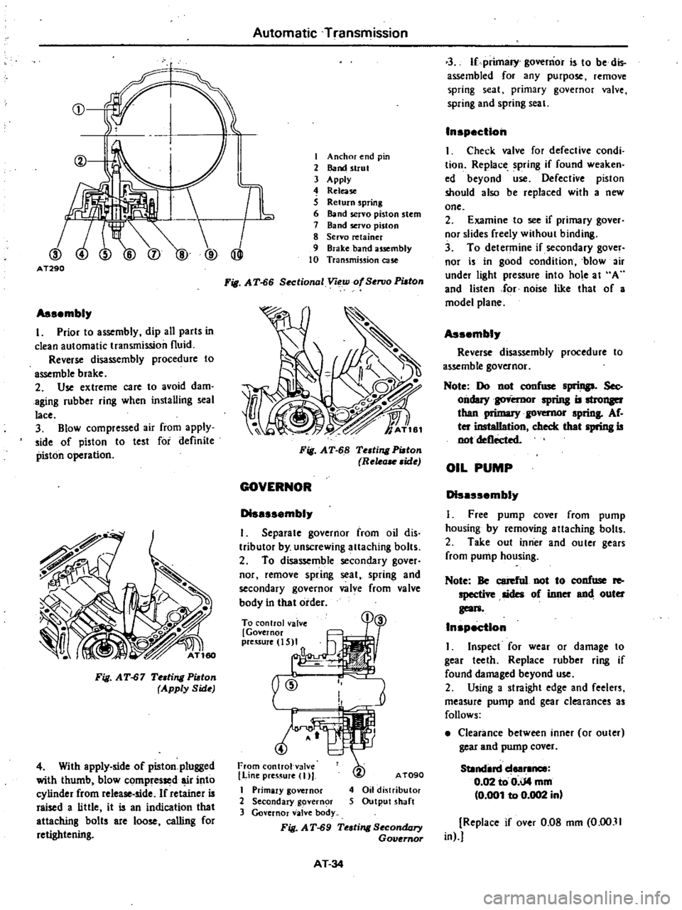
CD
@
I
I
TL
@
@
AT290
Assembl
I
Prior
to
assembly
dip
all
parts
in
clean
automatic
transmission
fluid
Reverse
disassembly
procedure
to
assemble
brake
2
Use
extreme
care
to
avoid
dam
aging
rubber
ring
when
installing
seal
lace
3
Blow
compressed
air
from
apply
side
of
piston
to
test
for
definite
piston
operation
Fig
AT
67
Te
ling
Pi
ton
Apply
Side
4
With
apply
side
of
piston
plugged
with
thumb
blow
compressed
r
into
cylinder
from
release
side
If
retainer
is
raised
a
little
it
is
an
indication
that
attaching
bolts
are
loose
calling
for
retightening
Automatic
Transmission
I
Anchor
end
pin
2
Band
strut
3
Apply
4
Release
S
Return
spring
6
Band
servo
piston
stem
7
Band
servo
piston
8
Servo
retainer
9
Brake
band
usembly
10
Transmission
cue
Fig
A
T
66
Sectional
Voew
of
SenJo
PUlOn
Fig
AT
68
Te
ting
Pi
ton
Rele
ide
GOVERNOR
D1sessembl
I
Separate
governor
from
oil
dis
tributor
by
unscrewing
attaching
bolts
2
To
disassemble
secondary
gover
nor
remove
spring
seat
spring
and
secondary
governor
valve
from
valve
body
in
that
order
To
control
valve
Governor
preuure
IS
I
a
@
From
control
val
e
I
Line
preS
UJe
I
I
Primary
governor
2
Secondary
govern
r
3
Governor
valve
body
Fig
AT
69
Te
ling
SecondQry
Governor
AT090
4
Oil
dj
tributor
5
Output
shaft
AT
34
3
If
primary
governor
is
to
be
dis
assembled
for
any
purpose
remove
spring
seat
primary
governor
valve
spring
and
spring
seal
Inspection
I
Check
valve
for
defective
condi
tion
Replace
spring
if
found
weaken
ed
beyond
use
Defective
piston
should
also
be
replaced
with
a
new
one
2
Examine
to
see
if
primary
gover
nor
slides
freely
without
binding
3
To
determine
if
secondary
gover
nor
is
in
good
condition
blow
ir
under
light
pressure
into
hole
at
A
and
listen
for
noise
like
thaI
of
a
model
plane
Assembl
Reverse
disassembly
procedure
to
assemble
governor
Note
Do
not
confuse
spriDp
Sec
ondary
spring
is
than
1
governor
sprinS
Af
ter
insteIIation
check
thet
spring
is
not
deflected
OIL
PUMP
D1sessembl
I
Free
pump
cover
from
pump
housing
by
removing
allaching
bolts
2
Take
out
inner
and
ouler
gears
from
pump
housing
Note
Be
cerefnl
not
to
confuse
Ie
specti
sides
of
inner
end
outer
geon
Inspection
I
Inspect
for
wear
or
damage
to
gear
teeth
Replace
rub
bel
ring
if
found
damaged
beyond
use
2
Using
a
straight
edge
and
feelers
measure
pump
and
gear
clearances
as
follows
Clearance
between
inner
or
outer
gear
and
pump
cover
SUndin
deer1lnee
0
02
to
0
iJ4
mm
0
001
to
0
002
in
Replace
if
over
0
08
mm
0
00
11
in
Page 310 of 548
I
powder
and
oil
applied
sp
hingly
to
all
ring
gear
teeth
For
the
tooth
contact
pattern
see
paragraph
dealing
with
tooth
contact
pattern
adjustl1ll
nt
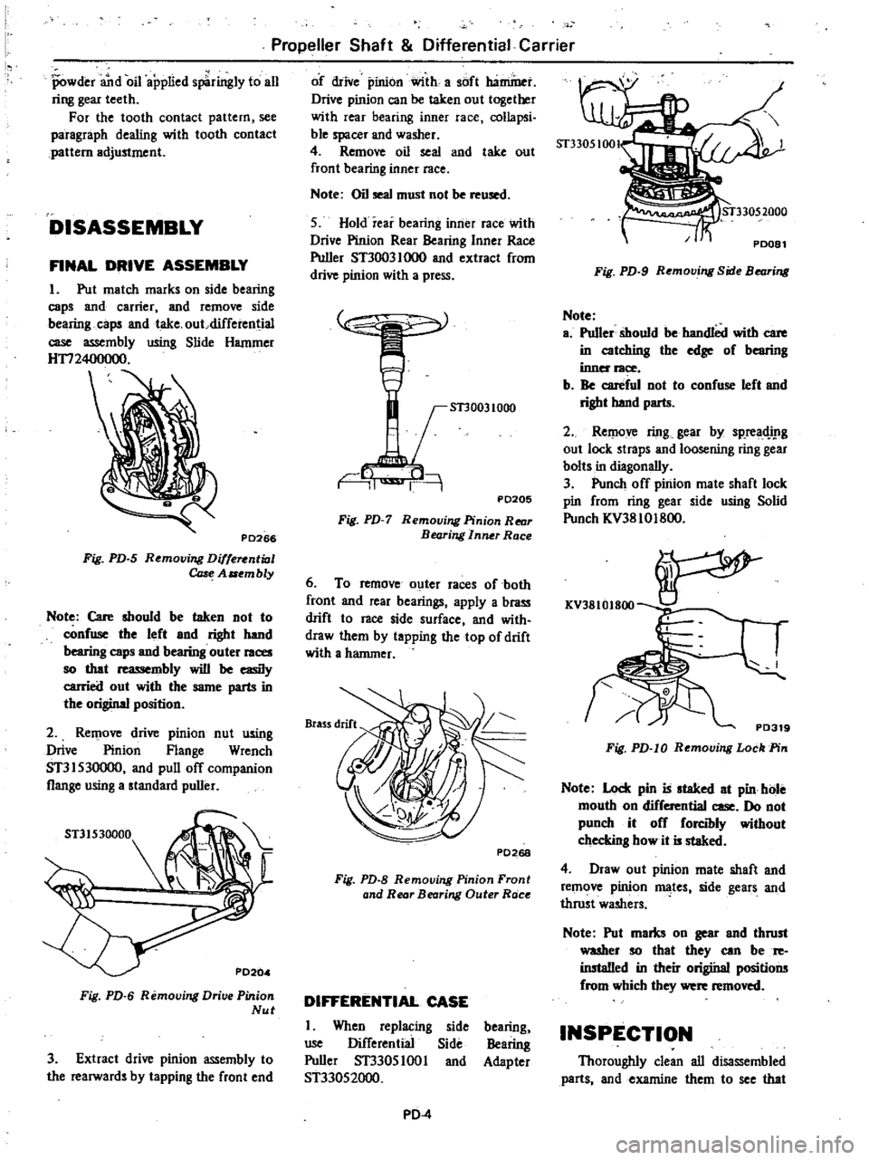
DISASSEMBLY
FINAL
DRIVE
ASSEMBLY
I
Put
match
marks
on
side
bearing
caps
and
carrier
and
remove
side
bearing
caps
and
take
out
differential
case
assembly
using
Slide
Hammer
HTI2400000
PD266
Fig
PD
5
Removing
Diffe
ntial
Ca
e
A
embly
Note
Care
should
be
taken
not
to
confWle
the
left
end
right
hand
bearing
caps
and
bearing
outer
races
so
that
reassembly
will
be
easily
carried
out
with
the
same
parts
in
the
original
position
2
Rel
love
drive
pinion
nut
using
Drive
Pinion
Flange
Wrench
ST31530000
and
pull
off
companion
flange
using
a
standard
puller
Fig
PD
6
Removing
Drive
Pinion
Nut
3
Extract
drive
pinion
assembly
to
the
rearwards
by
tapping
the
front
end
Propeller
Shaft
Differential
Carrier
of
drive
pinion
with
a
soft
baminet
Drive
pinion
can
be
taken
out
together
with
rear
bearing
inner
race
collapsi
ble
spacer
and
washer
4
Remove
oil
seal
and
take
out
front
bearing
inner
race
Note
Oil
seal
must
not
be
reused
5
Hold
rear
bearing
inner
race
with
Drive
Pinion
Rear
Bearing
Inner
Race
Puller
ST30031000
and
extract
from
drive
pinion
with
a
press
STJ0031000
r
1
i
9
PD205
Fig
PD
7
Removing
Pinion
Rear
Bearing
I
nfUr
Race
6
To
remove
outer
races
of
both
front
and
rear
bearings
apply
a
brass
drift
to
race
side
surface
and
with
draw
them
by
tapping
the
top
of
drift
with
a
hammer
PD268
Fig
PD
B
Removing
Pinion
Front
and
Rear
Bearing
Outer
Race
DIFFERENTIAL
CASE
I
When
replacing
side
Wle
Differenliai
Side
Puller
ST3305
1001
and
ST33052000
bearing
Bearing
Adapter
PD
4
Fig
PD
9
Removing
Side
Bearing
Note
a
Puller
should
be
bandlOd
with
care
in
catching
the
edge
of
bearing
inner
race
b
Be
careful
not
to
confuse
left
and
right
band
parts
2
Rel
love
ring
gear
by
sp
readJ
lg
out
lock
straps
and
loosening
ring
gear
bolts
in
diagonally
3
Punch
off
pinion
mate
shaft
lock
pin
from
ring
gear
side
using
Solid
Punch
KV3810Ig00
KV3810I800
PD319
Fig
PD
I0
Removing
Lock
Pin
Note
Lock
pin
is
slaked
et
pin
hole
mouth
on
differential
case
Do
not
punch
it
off
forcibly
without
checking
how
it
is
staked
4
Draw
out
pinion
mate
shaft
and
remove
pinion
ID3
tes
side
gears
and
thrust
washers
Note
Put
mams
on
gear
end
thrust
waaher
so
that
they
can
be
re
installed
in
their
origiital
positions
from
which
they
were
removed
INSPECTION
Thoroughly
clean
all
disassembled
parts
and
examine
them
to
see
that