battery location DATSUN 210 1979 Service Manual
[x] Cancel search | Manufacturer: DATSUN, Model Year: 1979, Model line: 210, Model: DATSUN 210 1979Pages: 548, PDF Size: 28.66 MB
Page 19 of 548

sion
pressure
chances
are
that
piston
rings
are
worn
or
damaged
2
If
pressure
stays
low
the
likeli
hood
is
that
valve
is
sticking
or
seating
Engine
Tune
up
improperly
3
If
cylinder
compression
in
any
two
adjacent
cylinders
is
low
and
if
adding
oil
does
not
help
the
compres
sion
there
is
leakage
past
the
gasketed
surface
Oil
and
water
in
combustion
cham
bers
can
result
from
this
problem
IGNITION
AND
FUEL
SYSTEM
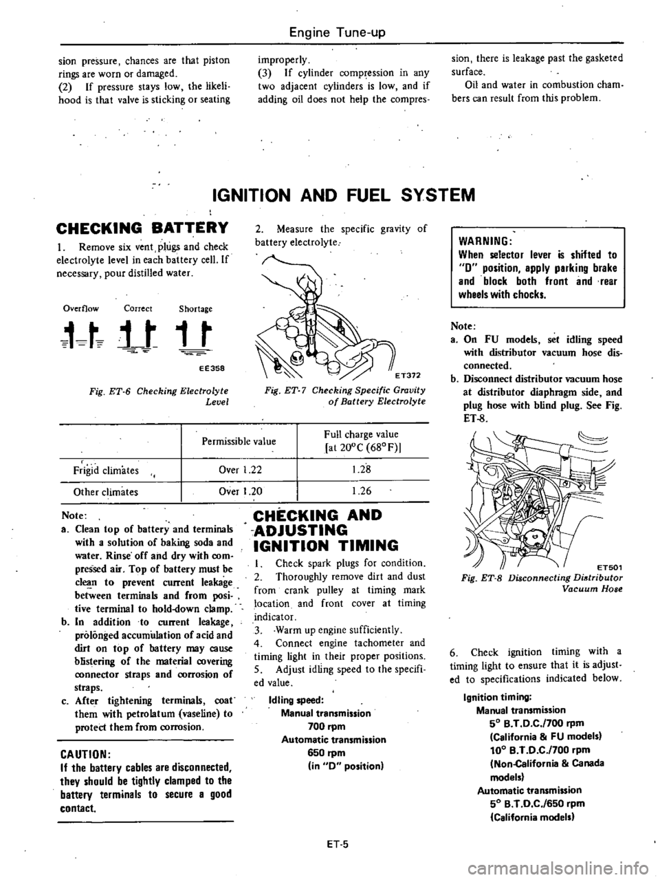
CHECKING
BATTERY
I
Remove
six
vent
plugs
and
check
electrolyte
level
in
each
battery
cell
If
necessary
pour
distilled
water
Overflow
Correct
Shortage
t
t
j
t
t
t
EE358
Fig
ET
6
Checking
Electrolyte
Level
2
Measure
the
specific
gravity
of
battery
electrolyte
E
T372
Fig
ET
7
Checking
Specific
Gravity
of
Battery
Electrolyte
Over
1
22
Full
charge
value
at
200C
680F
1
28
1
26
Permissible
value
Frigid
climates
Other
climates
Note
a
Clean
top
of
battery
and
terminals
with
a
solution
of
baking
soda
and
water
Rinse
off
and
dry
with
com
pressed
air
Top
of
battery
must
be
c1
n
to
prevent
current
leakage
between
terminals
and
from
posi
tive
terminal
to
hold
down
clamp
b
In
addition
to
current
leakage
prolonged
accumulation
of
acid
and
dirt
on
top
of
hattery
may
cause
blistering
of
the
material
covering
ronnector
straps
and
rorrosion
of
straps
c
Afte
r
tightening
terminals
coat
them
with
petrolatum
vaseline
to
protect
them
from
corrosion
CAUTION
If
the
battery
cables
are
disconnected
they
should
be
tightly
clamped
to
the
battery
terminals
to
secure
a
good
contact
Over
I
20
CHECKING
AND
ADJUSTING
IGNITION
TIMING
Check
spark
plugs
for
condition
2
Thoroughly
remove
dirt
and
dust
from
crank
pulley
at
timing
mark
location
and
front
cover
at
timing
indicator
3
Warm
up
engine
sufficiently
4
Connect
engine
tachometer
and
timing
light
in
their
proper
positions
5
Adjust
idling
speed
to
the
specifi
ed
value
Idling
speed
Manual
transmission
700
pm
Automatic
transmission
6S0
rpm
in
0
position
ET
S
WARNING
When
selector
lever
is
shifted
to
0
position
apply
parking
brake
and
block
both
front
and
rear
wheels
with
chocks
Note
a
On
FU
models
set
idling
speed
with
distributor
vacuum
hose
dis
connected
b
Disconnect
distributor
vacuum
hose
at
distributor
diaphragm
side
and
plug
hose
with
blind
plug
See
Fig
ET
8
ET501
Fig
ET
B
Disconnecting
Distributor
Vacuum
Hose
6
Check
ignition
timing
with
a
timing
light
to
ensure
that
it
is
adjust
ed
to
specifications
indicated
below
Ignition
timing
Manual
transmission
SO
B
T
0
C
f700
rpm
California
FU
models
100
B
T
0
C
f700
pm
Non
California
Canada
models
Automatic
transmission
SO
B
T
0
C
f6S0
rpm
California
models
Page 102 of 548

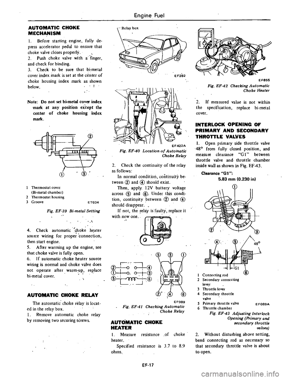
AUTOMATIC
CHOKE
MECHANISM
I
Before
starting
engine
fully
de
press
accelerator
pedal
to
ensure
that
choke
valve
closes
properly
2
Push
choke
valve
wi
th
a
finger
and
check
for
binding
3
Check
to
be
sure
that
bi
metal
cover
index
mark
is
set
at
the
center
of
choke
housing
index
mark
as
shown
below
I
Note
Do
not
set
b
metal
cover
index
mark
at
any
position
except
the
center
of
choke
housing
index
mark
CD
@
Thermosta
t
covel
Bi
metal
chamber
2
Thermostat
housing
3
Groove
E
T034
Fig
EF
39
Bi
metal
Setting
4
Check
automatic
choke
heater
source
wiring
for
proper
connection
then
start
engine
S
After
warming
up
the
engine
see
that
choke
valve
is
fully
open
6
If
automatic
choke
heater
source
wiring
is
normal
and
choke
valve
does
not
operate
after
warm
up
replace
bi
metal
cover
AUTOMATIC
CHOKE
RELAY
The
automatic
choke
relay
is
local
ed
in
the
relay
box
I
Remove
automatic
choke
relay
by
removing
two
securing
screws
Engine
Fuel
II
EF422A
Fig
EF
40
Location
of
Automatic
Choke
Relay
2
Check
the
continuity
of
the
relay
as
follows
In
normal
condition
continuity
be
tween
CV
and
@
should
exist
Then
apply
l2V
battery
voltage
across
CID
and
@
Under
this
condi
tion
contin
ity
between
CV
and
@
should
disappear
If
not
the
relay
is
faulty
replace
it
W
hWO
CID
CD
CV
o
0
@
Q
I
o
r
@
CID
@
EF989
Fig
EF
41
Checking
Automatic
Choke
Relay
AUTOMATIC
CHOKE
HEATER
I
Measure
resistance
of
choke
heater
Specified
resistance
is
3
7
to
8
9
ohms
EF
17
EF855
Fig
EF
42
Checking
Automatic
Choke
Heater
2
If
measured
value
is
not
within
the
specification
replace
bi
metal
cover
INTERLOCK
OPENING
OF
PRIMARY
AND
SECONDARY
THROTTLE
VALVES
1
Open
primary
side
throttle
valve
480
from
fully
closed
position
and
measure
clearance
G
1
between
throttle
valve
and
throttle
chamber
inside
wall
as
shown
in
Fig
EF
43
Clearance
6G1
5
83
mm
0
230
in
@
J
3
480
r
mit
GI
6
1
Connecting
rod
2
Secondary
connecting
lever
3
Throttle
lever
4
Secondary
throttle
valve
5
Primary
throttle
valve
6
Throttle
chamber
Fig
EF
43
Adjusting
Interlock
Opening
Primary
and
lecondary
throttle
values
2
Without
disturbing
above
setting
bend
connecting
rod
as
necessary
so
that
secondary
throttle
valve
is
about
to
open
E
F089A
Page 199 of 548

REMOVAL
It
is
much
easier
to
remove
engine
and
transmission
as
a
single
unit
than
to
remove
alone
After
removal
engine
can
be
separated
from
the
transmission
assembly
WARNING
a
Place
wheel
chocks
in
fronl
of
front
wheels
and
in
rear
of
rear
wheels
b
Be
sure
to
hoist
engine
in
a
safe
manner
c
You
should
not
remove
engine
until
exhaust
system
has
com
pletely
cooled
off
Otherwise
you
may
burn
your
self
and
or
fire
may
break
out
in
fuel
line
Note
Fender
coven
should
be
used
to
protect
car
body
1
Disconnect
battery
ground
cable
from
battery
terminal
and
fusible
link
at
wire
connector
2
Remove
hood
as
follows
CAUTION
Have
an
assistant
help
you
so
as
to
prevent
damage
to
body
I
Mark
hood
hinge
locations
on
hood
to
facilitate
reinstallation
2
Support
hood
by
ltand
and
re
move
bolts
securing
it
to
hood
hinge
being
careful
not
to
let
hood
slip
when
bolts
are
removed
See
Fig
ER
2
3
Remove
hood
from
hood
hinge
f
Il
I
BF133A
Fig
ER
2
Removing
Hood
Remove
under
cover
Drain
radiator
coolant
and
engine
3
4
oil
5
Disconnect
upper
and
lower
hoses
from
radiator
and
disconnect
oil
cooler
hoses
automatic
transmission
only
6
Remove
four
bolts
securing
radia
Engine
Removal
Installation
tor
to
body
and
detach
radiator
after
removing
radiator
shroud
7
Remove
air
cleaner
assembly
from
carburetor
as
follows
1
Remove
fresh
air
duct
from
air
cleaner
2
Remove
hot
air
duct
from
air
cleaner
3
Loosen
air
cleaner
band
bolt
4
Disconnect
air
cleaner
to
air
pump
hose
at
air
cleaner
5
Disconnect
air
cleaner
ta
rocker
cover
hose
at
rocker
cover
6
Disconnect
air
cleaner
to
A
B
valve
hose
at
air
cleaner
7
Disconnect
air
cleaner
to
related
vacuum
hoses
at
air
cleaner
8
Disconnect
accelerator
control
wire
from
carburetor
9
Disconnect
the
following
cables
wires
and
hoses
Wire
to
auto
choke
heater
Wire
to
throttle
opener
cut
solenoid
or
throttle
switch
Wire
to
fuel
cut
solenoid
Wire
to
vacuum
switching
valve
High
tension
cable
between
igni
tion
coil
and
distributor
Battery
cable
to
starter
motor
Wire
to
distributor
Wire
to
thermal
transmitter
Wire
to
alternator
Engine
ground
cable
oil
pressure
switch
and
engine
harness
No
2
See
Fig
ER
3
o
1
Ground
cable
2
Engine
harness
No
2
3
Oil
pressure
switch
Fig
ER
3
EA368
Disconnecting
Cable
and
Wire
Fuel
hose
at
fuel
pump
and
fuel
return
hose
at
connection
Air
pump
air
cleaner
hose
Carbon
canister
hoses
Heater
inlet
and
outlet
hoses
if
so
equipped
ER
3
Vacuum
hose
of
brake
booster
at
intake
manifold
Air
conditioner
equipped
model
10
Remove
compressor
belt
To
remove
loosen
idler
pulley
nut
and
adjusting
bolt
1
Remove
air
pump
2
Remove
compressor
retaining
bolts
and
move
compressor
toward
fender
to
facilitate
removal
of
engine
Nole
Never
discharge
gas
from
com
pressor
while
work
is
being
per
formed
II
Compressor
EA478
Fig
ER
4
Location
of
Air
Compressor
3
Disconnect
vacuum
hose
of
air
conditioner
from
connector
of
intake
manifold
4
Remove
F
i
C
D
actuator
from
bracket
II
Remove
clutch
operating
cylin
der
from
clutch
housing
manual
trans
mission
only
dJ
Tightening
torque
Clutch
operating
cylinder
E
A3
to
clutch
housing
3
1
to
4
1
kg
22
to
30
ft
lbl
Fig
ER
5
Removing
Clutch
Operating
Cylinder