coolant level DATSUN 210 1979 Service Manual
[x] Cancel search | Manufacturer: DATSUN, Model Year: 1979, Model line: 210, Model: DATSUN 210 1979Pages: 548, PDF Size: 28.66 MB
Page 18 of 548

pl
ice
mter
as
an
assembly
2
When
installing
oil
mter
tighten
by
hand
Note
Do
not
overtighten
oil
filter
lest
leakage
shoUld
occur
CHANGING
ENGINE
COOLANT
PERMANENT
ANTI
FREEZE
COOLANT
Note
The
permanent
anti
freeze
coolant
is
an
ethylene
glya
l
base
product
containing
chemical
in
hibitors
to
protect
the
cooling
system
from
rusting
and
corrosion
The
anti
freeze
does
not
cOntain
any
glycerine
or
ethyl
alcohol
It
will
not
evaporate
or
boil
a
ay
and
can
be
ilsed
with
either
high
or
low
temperature
thermostats
It
flows
freely
transfers
heat
efficiently
and
will
not
clog
the
passages
in
the
cooling
system
The
anti
freeze
must
not
be
mixed
with
other
product
This
coolant
can
be
used
throughout
the
seasons
of
the
year
Whenever
coolant
is
changed
the
cooling
system
must
be
flushed
and
refilled
with
a
new
coolant
Check
the
coolant
level
See
instructions
attached
to
the
anti
freeze
container
for
mixing
ratio
of
anti
freeze
to
water
CHECKING
COOLING
SYSTEM
HOSES
AND
CONNECTIONS
Check
hoses
and
fittings
for
loose
connections
or
deterioration
Re
tighten
or
replace
if
necessary
INSPECTION
OF
RADIATOR
CAP
Apply
reference
pressure
0
9
kgj
cm2
13
psi
to
radiator
cap
by
means
of
a
cap
tester
to
see
if
it
is
satisfactory
Replace
cap
assembly
if
necessary
I
j
ngine
Tune
up
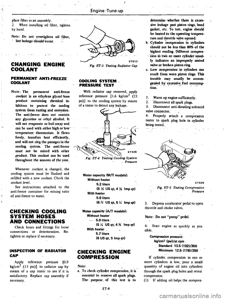
ET012
Fig
ET
3
Testing
Radiator
Cap
COOLING
SYSTEM
PRESSURE
TEST
Witli
radiator
cap
removed
apply
reference
pressure
1
6
kgfcm2
23
psi
to
the
cooling
system
by
means
0
no
Fig
ET
4
Water
capacity
M
Tmodelsl
Without
heater
5
2
liten
5
1f
US
qt
4
Imp
qt
With
heeter
5
9
Iiten
6
4
US
qt
5
Y
Imp
qt
Water
capacity
AfT
modelsl
Without
heater
5
0
liters
5
y
US
qt
4
Imp
qt
With
heater
5
7
liten
6
US
qt
5
Imp
ill
CHECKING
ENGINE
COMPRESSION
Note
a
To
check
cylinder
compression
it
is
essential
to
remove
all
spark
plugs
The
purpose
of
this
test
is
to
ET
4
determine
whether
there
is
exces
sive
leakage
past
piston
rings
head
gasket
etc
To
test
engine
should
be
heated
to
the
operating
t
M
ture
and
throttle
valve
opened
b
Cylinder
compre
on
in
Cylinders
should
not
be
less
than
llO
of
the
highest
reading
Different
compres
sion
in
two
ore
more
cYlinder
usual
ly
indicates
an
improperly
seated
valve
or
broken
piston
ring
c
Low
compression
in
cylinders
am
result
from
worn
piston
rings
This
trouble
may
usuaDy
be
accom
panied
by
ex
ssive
fuel
consump
tion
I
Warm
up
engine
sufficiently
2
Disconnect
aU
spark
plugs
3
Disconnect
anti
dieseling
solenoid
valve
connector
4
Properly
attach
a
compression
tester
to
spark
plug
hole
in
cylinder
being
tested
FiI
ET
S
ET529
Testing
Compre
sion
Pr
s8ure
5
Depress
accelenit6r
pedal
to
open
throttle
and
choke
valves
Note
Do
not
pump
pedal
6
Start
engine
as
quickly
as
pos
sible
Compression
pressllre
kg
cm2
ii
at
rpm
Standard
13
5
192
350
Minimum
12
5
1781
350
If
cylinder
compression
in
o
e
or
more
cylinders
is
low
pour
a
small
quantity
of
engine
oil
into
cylinders
through
the
spark
plug
holes
and
retest
compression
I
If
addingoil
helps
the
compres
Page 80 of 548

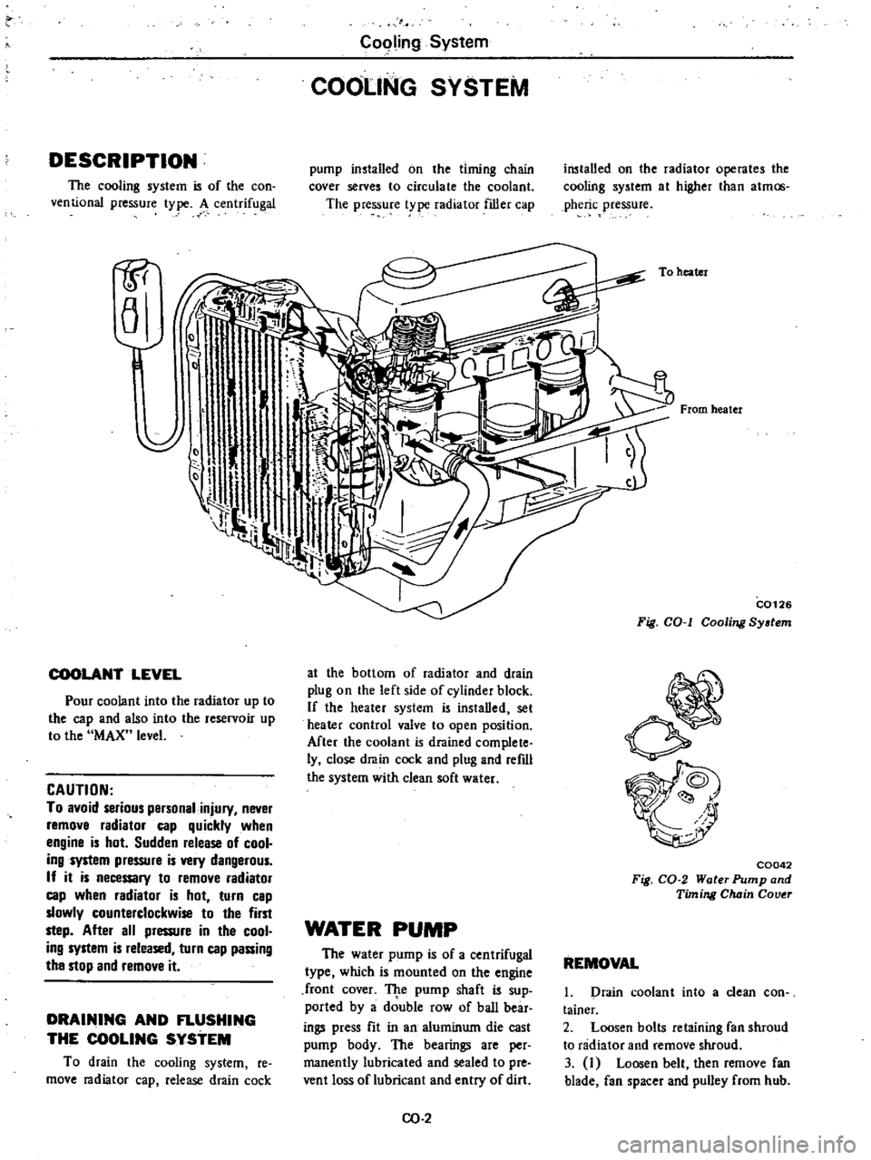
DESCRIPTION
The
cooling
system
is
of
the
con
ventional
pressure
type
A
centrifugal
1P
a
COOLANT
LEVEL
Pour
coolant
into
the
radiator
up
to
the
cap
and
also
into
the
reservoir
up
to
the
MAX
level
CAUTION
To
avoid
serious
personal
injury
never
remove
radiator
cap
quickly
when
engine
is
hot
Sudden
release
of
cool
ing
system
pressure
is
very
dangerous
If
it
is
necessary
to
remove
radiator
cap
when
radiator
is
hot
turn
cap
slowly
counterclockwise
to
the
first
step
After
all
pressure
in
the
cool
ing
system
is
released
turn
cap
passing
the
stop
and
remove
it
DRAINING
AND
FLUSHING
THE
COOLING
SYSTEM
To
drain
the
cooling
system
re
move
radiator
cap
release
drain
cock
C09ling
System
COOLING
SYSTEM
pump
installed
on
the
timing
chain
cover
serves
to
circulate
the
coolant
The
pressure
t
pe
radiator
filler
cap
at
the
bottom
of
radiator
and
drain
plug
on
the
left
side
of
cylinder
block
If
the
heater
system
is
instaDed
set
heater
control
valve
to
open
position
Mter
the
coolant
is
drained
complete
ly
close
drain
cock
and
plug
and
refdl
the
system
with
clean
soft
water
WATER
PUMP
The
water
pump
is
of
a
centrifugal
type
which
is
mounted
on
the
engine
front
cover
TJ
te
pump
shaft
is
sup
ported
by
a
double
row
of
baD
bear
ings
press
fit
in
an
aluminum
die
cast
pump
body
The
bearings
are
per
manently
lubricated
and
sealed
to
pre
vent
loss
of
lubricant
and
entry
of
dirt
CO
2
installed
on
the
radiator
operates
the
cooling
system
at
higher
than
atmos
pheric
pressure
To
heater
From
heater
C0126
Fig
COol
Cooling
System
C0042
Fig
CO
2
Water
Pump
and
Timing
Chain
Couer
REMOVAL
1
Drain
coolant
into
a
clean
con
tainer
2
Loosen
bolts
retaining
fan
shroud
to
radiator
and
remove
shroud
3
I
Loosen
belt
then
remove
fan
blade
fan
spacer
and
pulley
from
hub
Page 84 of 548

u
V
O
I
MAX
Ii
1i
i
iT
1
I
I
11
1
i
MINij
o
f
G
p
rl
MAX
ii
i
p
It
ot
MINi
II
L
Cooling
System
l
CQ074
Pressure
relief
valve
opens
f
C007S
Vacuum
valve
opens
INSPECTION
1
Check
the
amount
of
coolant
in
the
reservoir
tank
If
the
coolant
level
is
below
the
MIN
level
remove
the
re
servoirtank
ruler
cap
and
add
enough
oolant
to
reach
MAX
level
If
the
reservoir
tank
is
empty
check
the
coolantlevel
in
the
radiator
If
the
coolant
in
the
radiator
is
insuf
ficient
pour
it
into
radiator
up
to
the
radiator
cap
and
also
pour
it
into
the
reservoir
tank
until
MAX
level
If
the
coolant
in
the
reservoir
tank
d
ecreases
abnormally
rapid
check
for
a
leak
in
the
cooling
system
REMOVAL
AND
INSTALLATION
1
Reservoir
tank
is
only
inserted
to
reservoir
tank
bracket
and
can
be
easily
removed
To
install
reservoir
tank
reverse
the
order
of
remova
Fig
CO
12
Opefation
of
ReserVoir
Tank
SERVICE
DATA
AND
SPECIFICATIONS
Thermostat
Valve
opening
temperature
Oc
OF
Maximum
valve
lift
mmjOC
in
oF
Radiator
Type
Manual
transmission
Automatic
tralUJ1lission
Cap
relief
pressure
kg
cm2
psi
Testing
pressure
kg
cm
2
psi
Fan
Fan
belt
deflection
mm
in
cO
6
Temperate
type
Frigid
type
Tropical
type
82
180
88
190
76
5
I
70
8
95
8
loo
8
90
0
3
I
203
0
31j2
i
2
0
31
194
Corrugated
fm
type
Corrugated
fm
type
equipped
with
oil
cooler
0
9
I
3
1
6
23
8
to
12
0
31
to
0
47
Page 85 of 548

Condition
Loss
of
water
Poor
circulation
Corrosion
Overheating
Over
cooling
Cooling
System
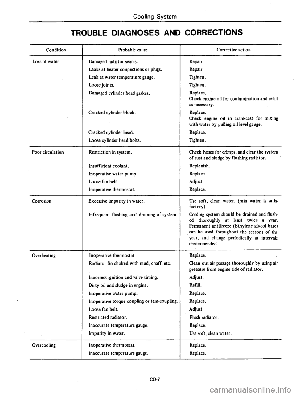
TROUBLE
DIAGNOSES
AND
CORRECTIONS
Probable
cause
Damaged
radiator
seams
Leaks
at
heater
connections
or
plugs
Leak
at
water
temperature
gauge
Loose
joints
Damaged
cylinder
head
gasket
Cracked
cylinder
block
Cracked
cylinder
head
Loose
cylinder
head
bolts
Restriction
in
system
Insufficient
coolant
Inoperative
water
pump
Loose
fan
belt
Inoperative
thermostat
Excessive
impurity
in
water
Infrequent
flushing
and
draining
of
system
Inoperative
thermostat
Radiator
fin
choked
with
mud
chaff
etc
Incorrect
ignition
and
valve
timing
Dirty
oil
and
sludge
in
engine
Inoperative
water
pump
Inoperative
torque
coupling
or
tem
coupling
Loose
fan
belt
Restricted
radiator
Inaccurate
temperature
gauge
Impurity
in
water
Inoperative
thermostat
Inaccurate
temperature
gauge
CO
7
Corrective
action
Repair
Repair
Tighten
Tighten
Replace
Check
engine
oil
for
contamination
and
reml
as
necessary
Replace
Check
engine
oil
in
crankcase
for
mixing
with
water
by
pulling
oil
level
gauge
Replace
Tighten
Check
hoses
for
crimps
and
clear
the
system
of
rust
and
sludge
by
flushing
radiator
Replenish
Replace
Adjust
Replace
Use
soft
clean
water
rain
water
is
satis
factory
Cooling
system
should
be
drained
and
flush
ed
thoroughly
at
least
twice
a
year
Permanent
antifreeze
Ethylene
glycol
base
can
be
used
throughout
the
seasons
of
the
year
and
change
periodically
at
intervals
recommended
Replace
Clean
out
air
passage
thoroughly
by
using
air
pressure
from
engine
side
of
radiator
Adjust
Refill
Replace
Replace
Adjust
Flush
radiator
Replace
Use
soft
dean
water
Replace
Replace
Page 293 of 548

with
the
pin
hole
of
the
internal
rotor
combined
with
the
manual
shaft
and
check
their
alignment
by
inserting
a
1
5
mm
0
059
in
diameter
pin
into
the
holes
If
the
alignment
is
correct
fasten
the
switch
body
with
the
bolts
pull
out
the
pin
tighten
up
the
screw
in
the
hole
and
fasten
the
selector
lever
as
before
Check
the
continuity
pin
with
the
lesler
If
Ihe
malfunc
tion
still
remains
replace
the
inhibitor
switch
STALL
TEST
The
purpose
of
this
test
is
to
check
the
transmission
and
engine
for
trou
ble
by
measuring
the
maximum
num
bers
of
revoiutions
o
the
cngine
while
vehicle
is
held
in
a
stalled
condition
The
carburetor
is
in
fullthrollle
opera
tion
with
the
selector
lever
in
ranges
1
2
and
I
respectively
Com
pale
the
measured
results
with
the
standard
values
Components
to
be
tested
and
test
itelJUl
I
Clutches
brake
and
band
in
trans
mission
for
slipping
2
Torque
converter
for
proper
func
tioning
3
Engine
for
overall
properly
STAU
TEST
PROCEDURES
Before
testing
check
the
engine
oil
and
torque
converter
oil
warm
up
the
engine
cooling
w
ter
to
suitable
tem
perature
by
running
at
1
200
rpm
with
the
selector
lever
in
the
range
P
for
sevcral
minutes
Warm
up
the
torque
converter
oil
to
suitable
temperature
60
to
lOOoC
140
to
2120F
I
Mount
the
engine
tachometer
at
a
location
that
allows
good
visibility
from
the
driver
s
seat
and
put
a
mark
on
specified
revolutions
on
the
meter
2
Secure
the
front
and
rear
wheels
with
chocks
and
apply
the
hand
brake
Be
SIIre
to
depress
the
brake
pedal
firmly
with
the
left
foot
before
de
pressing
the
accelerator
pedal
3
Throw
the
selector
lever
into
the
range
11
4
Slowly
depress
the
accelerator
pedal
until
the
throttle
valvc
is
fully
Automatic
Transmission
opened
Quickly
read
and
record
the
engine
revolution
when
the
engine
begins
to
rotate
steadily
and
then
release
the
accelerator
pedal
5
Shift
the
selector
lever
to
N
and
operate
the
engine
at
approxi
mately
1
200
rpm
for
more
than
one
minute
to
cool
down
the
torque
con
verter
oil
and
coolant
6
Make
similar
staU
tests
in
ranges
2
I
and
R
CAUTION
The
dill
test
operstion
81
specified
in
i18m
4
should
be
I118de
within
fiv
lIeonds
If
it
tBkes
too
long
the
oil
If
and
the
cluti
hn
blllke
and
b
nd
elll
ly
I
Suf
ficient
cooling
time
should
be
given
r
eech
test
for
the
four
IlInges
0
Z
1
end
R
JUDGEMENT
High
stall
revolution
more
than
staitdard
revolution
If
the
engine
levolulion
in
stall
condi
ion
is
higher
than
the
standard
values
it
indicates
that
onc
or
more
clutches
in
the
transmission
are
slipping
and
therefore
no
further
test
is
required
For
the
following
abnormalities
the
respective
causes
are
presumed
High
rpm
in
all
ranges
low
line
pr
ssure
High
rpm
in
0
2
and
I
and
normal
rpm
in
6R
Rear
clutch
slipping
High
rpm
in
D
and
2
and
normal
rpm
in
One
way
clutch
slipping
High
Ipm
in
R
only
Front
clutch
or
low
and
reverse
brake
slipping
To
determine
which
is
slipping
front
clutch
or
low
and
reverse
brake
a
road
test
is
needed
If
while
coasting
after
starting
with
the
levcr
in
I
range
engine
braking
does
not
work
properly
the
low
and
reverse
brake
is
slipping
Otherwise
the
front
clutch
is
slipping
Slipping
of
the
band
brake
is
diffi
cuJt
to
ascertain
However
jf
it
occurs
with
the
lever
in
1
range
engine
AT
41
revolution
increases
up
to
the
same
level
as
in
1st
range
It
is
impossible
to
check
it
in
the
stall
test
2
Standard
stall
rnoluiion
If
the
engine
revoluiion
in
stall
ondition
is
within
he
standard
values
the
control
elements
are
nOf
mally
operating
in
the
ranges
D
2n
I
and
R
Also
the
engine
and
one
way
clutch
of
the
torque
converter
are
norinal
in
performance
and
operation
The
one
way
clutch
of
the
torque
converter
however
sometimes
sticks
This
is
determined
in
the
road
test
3
Lower
stall
revolution
than
lIand
ard
revolution
If
the
engine
revolution
in
stall
condition
is
lower
than
the
standard
values
it
indicates
that
the
engine
is
in
abnormal
condition
or
the
torque
con
verter
s
one
way
clutch
is
slipping
4
O
hers
I
If
the
accelerating
performance
is
poor
until
vehicle
speed
of
approxi
mately
SO
kmfh
30
MPH
is
attained
and
then
normal
beyond
that
speed
it
can
be
judged
that
the
torque
con
verte
c
s
one
way
clutch
is
slipping
2
If
the
torque
converter
sane
way
dutch
sticks
vehicle
speed
can
not
exceed
approximately
80
kmfh
SO
MPH
in
the
road
tesl
In
such
a
case
the
torque
converter
oil
tem
perature
rises
abnormally
and
so
special
care
is
required
3
If
the
transmission
does
not
op
erate
properly
at
all
vehicle
speeds
it
indicates
poor
engine
performance
ROAD
TEST
An
accurate
knowledge
of
the
au
to
matic
transmission
is
required
for
an
exact
diagnosis
II
is
recommended
that
a
diagnosis
guide
chart
with
the
standard
vehicle
speeds
for
each
stage
of
the
up
and
down
shiftings
be
prepared
Measured
vehicle
speeds
are
to
be
filled
in
the
adjoining
column
after
each
testing
Also
it
is
advisable
to
mount
a
stopper
for
positioning
the
throttle
opening
Page 456 of 548

ILLUMINATION
CONTROL
UNIT
Body
Electrical
System
8
GY
GW
AIMING
ADJUSTMENT
To
adjust
vertical
aim
use
adjusting
screw
on
upper
side
of
headlamp
and
to
adjust
horizontal
ailn
use
adjusting
screw
on
side
of
headlamp
BE1200
Fig
BE
I3
Illumination
Control
Unit
1
Vertical
adjustment
2
Horizontal
adjustment
BE1210
Fig
BE
14
Aiming
Ad
iusting
Screws
Note
Before
makiiIg
headlamp
aim
ing
adjustment
observe
the
follow
ing
instructions
a
Keep
all
tires
inflated
to
correct
pressures
b
Place
car
and
tester
on
one
and
BE
11
same
flat
surface
c
See
that
there
is
no
load
in
car
coolant
engine
oil
fIlled
up
to
correct
level
and
full
fuel
tank
other
than
the
driver
or
equivalent
weight
placed
in
driver
s
position
d
For
details
refer
to
SAE
J599d
When
performing
headlamp
aiming
adjustment
use
an
aiming
machine
aiming
wall
screen
or
headlamp
tester
For
operating
instructions
of
any
almer
it
should
be
in
good
repair
calibrated
and
used
accordi
g
to
respective
operation
manuals
supplied
with
the
unit
If
any
aimer
is
not
available
aiming
adjustment
can
be
done
as
follqws
Turn
headlamp
low
beam
on
H
Horizontal
center
line
of
headlamps
BE297D
Fig
BE
I5
Aiming
Adjustment
Unit
mm
in
Note
a
Adjust
headlamps
so
that
upper
edge
of
hot
spot
is
equal
in
height
to
headlamp
height
and
left
edge
of
hot
spot
is
equal
in
height
to
each
center
line
of
headlamps
b
Dotted
lines
in
illustration
show
center
of
headlamp