coolant reservoir DATSUN 210 1979 Service Manual
[x] Cancel search | Manufacturer: DATSUN, Model Year: 1979, Model line: 210, Model: DATSUN 210 1979Pages: 548, PDF Size: 28.66 MB
Page 80 of 548

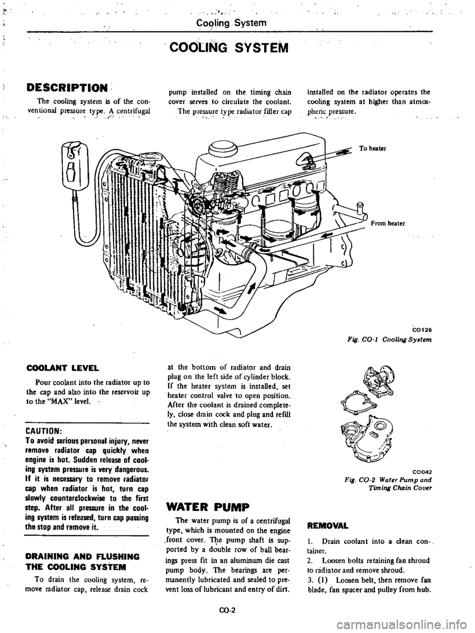
DESCRIPTION
The
cooling
system
is
of
the
con
ventional
pressure
type
A
centrifugal
1P
a
COOLANT
LEVEL
Pour
coolant
into
the
radiator
up
to
the
cap
and
also
into
the
reservoir
up
to
the
MAX
level
CAUTION
To
avoid
serious
personal
injury
never
remove
radiator
cap
quickly
when
engine
is
hot
Sudden
release
of
cool
ing
system
pressure
is
very
dangerous
If
it
is
necessary
to
remove
radiator
cap
when
radiator
is
hot
turn
cap
slowly
counterclockwise
to
the
first
step
After
all
pressure
in
the
cool
ing
system
is
released
turn
cap
passing
the
stop
and
remove
it
DRAINING
AND
FLUSHING
THE
COOLING
SYSTEM
To
drain
the
cooling
system
re
move
radiator
cap
release
drain
cock
C09ling
System
COOLING
SYSTEM
pump
installed
on
the
timing
chain
cover
serves
to
circulate
the
coolant
The
pressure
t
pe
radiator
filler
cap
at
the
bottom
of
radiator
and
drain
plug
on
the
left
side
of
cylinder
block
If
the
heater
system
is
instaDed
set
heater
control
valve
to
open
position
Mter
the
coolant
is
drained
complete
ly
close
drain
cock
and
plug
and
refdl
the
system
with
clean
soft
water
WATER
PUMP
The
water
pump
is
of
a
centrifugal
type
which
is
mounted
on
the
engine
front
cover
TJ
te
pump
shaft
is
sup
ported
by
a
double
row
of
baD
bear
ings
press
fit
in
an
aluminum
die
cast
pump
body
The
bearings
are
per
manently
lubricated
and
sealed
to
pre
vent
loss
of
lubricant
and
entry
of
dirt
CO
2
installed
on
the
radiator
operates
the
cooling
system
at
higher
than
atmos
pheric
pressure
To
heater
From
heater
C0126
Fig
COol
Cooling
System
C0042
Fig
CO
2
Water
Pump
and
Timing
Chain
Couer
REMOVAL
1
Drain
coolant
into
a
clean
con
tainer
2
Loosen
bolts
retaining
fan
shroud
to
radiator
and
remove
shroud
3
I
Loosen
belt
then
remove
fan
blade
fan
spacer
and
pulley
from
hub
Page 83 of 548

10
Replenish
coolant
and
check
for
leaks
INSPECTION
I
Submerge
thermostat
in
hot
water
SOC
90F
above
the
specified
temperature
Refer
to
Service
Data
and
Specifications
2
After
preparing
for
the
marked
screwdriver
at
about
8
mm
0
31
in
from
the
tip
inspect
the
lift
height
H
of
valve
by
inserting
it
f
C0097
Fig
CO
g
In
pecting
Thermostat
3
Now
place
thermostat
in
water
SoC
90F
below
the
specified
temper
ature
If
thermostat
does
not
operate
at
the
above
specified
temperature
it
must
be
replaced
because
it
cannot
be
repaired
Note
If
necessary
check
a
new
ther
mostat
before
installing
it
in
the
engine
RADIATOR
The
radiator
filler
cap
is
designed
to
maintain
a
pre
set
pressure
0
9
kgfcm2
13
psi
above
atmospheric
pressure
The
relief
valve
consisting
of
a
blow
off
valve
and
a
vacuum
valve
helps
to
prevent
the
coolant
from
boiling
by
giving
pressure
to
it
How
ever
when
the
pressure
is
reduced
below
atmospheric
pressure
the
vacu
wn
valve
allows
air
to
re
enter
the
radiator
preventing
the
formation
ofa
vacuum
in
the
cooling
system
On
models
equipped
wi
th
the
au
to
malic
transmission
the
oil
cooler
is
Cooling
System
combined
with
the
radiator
to
cool
transmission
fluid
REMOVAL
AND
INSTALLATION
1
Drain
coolant
into
a
clean
con
tainer
2
Disconnect
radiator
upper
and
lower
hoses
On
models
with
automat
ic
transmission
disconnect
cooler
inlet
and
ou
tlet
lines
from
radiator
3
Rem
Ne
fan
shroud
retaining
bolts
and
remove
fan
shroud
4
Remove
radiator
retaining
bolts
and
then
remove
radiator
upward
S
I
nstaD
radiator
in
the
reverse
se
quence
of
removal
Note
the
fol
lowing
I
Insert
hoses
in
their
positions
until
they
bottom
2
Ensure
that
arrow
marks
on
hoses
are
clearly
visible
from
upper
direction
when
hoses
are
assembled
3
Ensure
that
clearance
between
radiator
hose
and
any
adjacent
parts
is
30
mm
1
18
in
min
On
air
condi
tioner
equipped
models
a
minimum
clearance
of
18
mm
0
71
in
should
exist
between
compressor
and
hose
4
Ensure
that
clearance
be
tween
shroud
and
fan
is
even
at
any
place
Note
Be
careful
not
to
damage
radi
ator
fins
and
core
tube
when
install
ing
INSPECTION
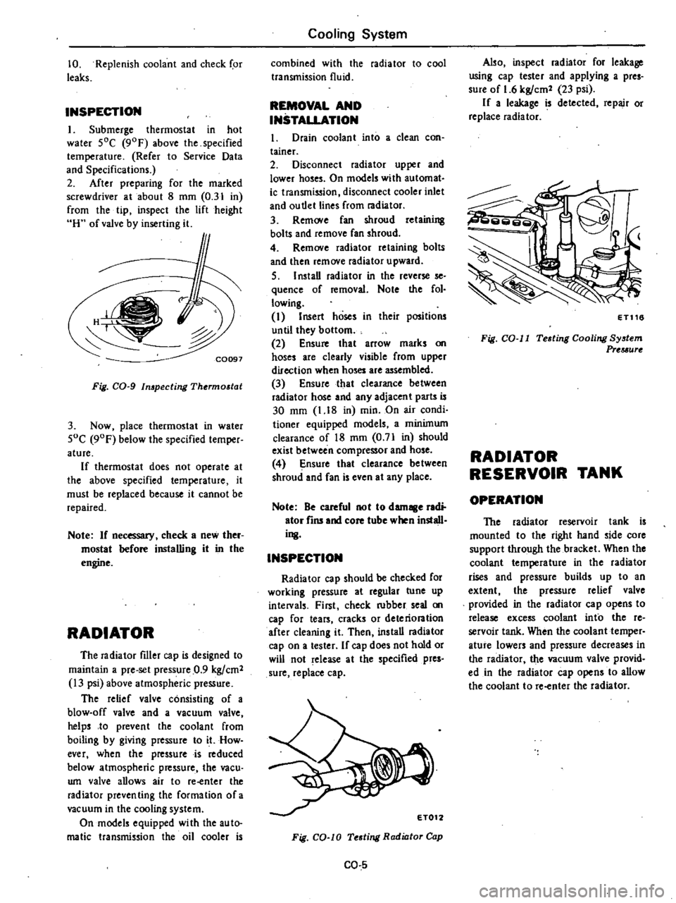
Radiator
cap
should
be
checked
for
working
pressure
at
regular
tune
up
intelVals
First
check
rubber
seal
on
cap
for
tears
cracks
or
deteriontion
after
cleaning
it
Then
ins
taD
radiator
cap
on
a
tester
If
cap
does
not
hold
or
will
not
release
at
the
specified
pres
sure
replace
cap
Fig
CO
lO
Testing
Radiator
Cap
CO
5
Also
inspect
radiator
for
leakage
using
cap
tester
and
applying
a
pres
sure
of
1
6
kgfcm2
23
psi
If
a
leakage
is
detected
repair
or
replace
radiator
ET116
Fig
CO
II
Testing
Cooling
System
Prtuurt
RADIATOR
RESERVOIR
TANK
OPERATION
The
radiator
reservoir
tank
is
mounted
to
the
right
hand
side
core
support
through
the
bracket
When
the
coolant
temperature
in
the
radiator
rises
and
pressure
builds
up
to
an
extent
the
pressure
relief
valve
provided
in
the
radiator
cap
opens
to
release
excess
coolant
into
the
re
servoir
tank
When
the
coolant
temper
ature
lowers
and
pressure
decreases
in
the
radiator
the
vacuum
valve
provid
ed
in
the
radiator
cap
opens
to
allow
the
coolant
to
re
enter
the
radiator
Page 84 of 548

u
V
O
I
MAX
Ii
1i
i
iT
1
I
I
11
1
i
MINij
o
f
G
p
rl
MAX
ii
i
p
It
ot
MINi
II
L
Cooling
System
l
CQ074
Pressure
relief
valve
opens
f
C007S
Vacuum
valve
opens
INSPECTION
1
Check
the
amount
of
coolant
in
the
reservoir
tank
If
the
coolant
level
is
below
the
MIN
level
remove
the
re
servoirtank
ruler
cap
and
add
enough
oolant
to
reach
MAX
level
If
the
reservoir
tank
is
empty
check
the
coolantlevel
in
the
radiator
If
the
coolant
in
the
radiator
is
insuf
ficient
pour
it
into
radiator
up
to
the
radiator
cap
and
also
pour
it
into
the
reservoir
tank
until
MAX
level
If
the
coolant
in
the
reservoir
tank
d
ecreases
abnormally
rapid
check
for
a
leak
in
the
cooling
system
REMOVAL
AND
INSTALLATION
1
Reservoir
tank
is
only
inserted
to
reservoir
tank
bracket
and
can
be
easily
removed
To
install
reservoir
tank
reverse
the
order
of
remova
Fig
CO
12
Opefation
of
ReserVoir
Tank
SERVICE
DATA
AND
SPECIFICATIONS
Thermostat
Valve
opening
temperature
Oc
OF
Maximum
valve
lift
mmjOC
in
oF
Radiator
Type
Manual
transmission
Automatic
tralUJ1lission
Cap
relief
pressure
kg
cm2
psi
Testing
pressure
kg
cm
2
psi
Fan
Fan
belt
deflection
mm
in
cO
6
Temperate
type
Frigid
type
Tropical
type
82
180
88
190
76
5
I
70
8
95
8
loo
8
90
0
3
I
203
0
31j2
i
2
0
31
194
Corrugated
fm
type
Corrugated
fm
type
equipped
with
oil
cooler
0
9
I
3
1
6
23
8
to
12
0
31
to
0
47