fuel type DATSUN 210 1979 Service Manual
[x] Cancel search | Manufacturer: DATSUN, Model Year: 1979, Model line: 210, Model: DATSUN 210 1979Pages: 548, PDF Size: 28.66 MB
Page 9 of 548
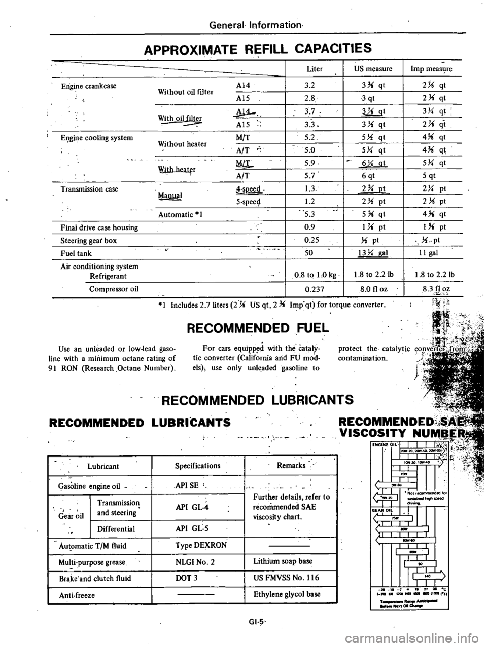
Erigine
crankcase
EI
gine
cooling
system
Transmission
case
Final
drive
case
housing
Steering
gear
box
Fuel
tank
Air
conditioning
system
Refrigerant
Compressor
oil
f
tl
It
J
4
i
1
protect
the
catalytic
cop
verter
froitr
contamination
t
n
General
Information
APPROXIMATE
REFILL
CAPACITIES
Without
oil
filter
AI4
Al5
w
Al5
M
T
AfT
MiL
A
T
Liter
US
measure
3
2
3
qt
2
8
3
qt
3
7
llLgt
33
3
qt
5
2
5
qt
5
0
5Y
qt
5
9
6
Y
at
57
6qt
1
3
2
Y
ot
1
2
2
pt
53
5
qt
0
9
1
pt
0
25
pt
50
13
Y
I
0
8
tol
Okg
1
8
to
2
2
1b
0
237
8
0
floz
Withoil
Without
heater
With
heatfr
MaDllal
soeed
5
spee
Automatic
1
1
Includes
2
7
liters
2
US
qt
2
Imp
qt
for
torque
converter
RECOMMENDED
FUEL
Use
an
unleaded
or
low
lead
gaso
line
with
a
minimum
octane
rating
of
91
RON
Research
Octane
Number
For
cars
equipp
d
with
the
Cataly
tic
converter
California
and
FU
mod
els
use
only
unleaded
gasoline
to
RECOMMENDED
Lubricant
GasOline
engine
oil
Gear
oil
Transmission
and
steering
Differential
Au
omatic
TIM
fluid
Multi
purpose
grease
Brake
and
clutch
fluid
Anti
freeze
L
NDED
LUBRICAN
COMMENDED
i
I
VISCOSITY
NUMBER
t1
NGON
0
L
J
I
j
H
I
IlL
I
t
l
I
lc
30
ItM
7
l
t
U
I
ItM
I
L
L
tJ
30
I
I
fu
JIl
inld
do
o
II
L
liOwl
1
I
I
1
10
I
I
I
I
t
I
I
j
r
I
I
J
1
21
l
1
I
71
c
DIUt
I2lItMOl
UGIIII
FI
R
NIl
I
01
a
Specifications
Remarks
APISE
API
GL4
Further
details
refer
to
recommended
SAE
viscosity
chart
API
GL
5
Type
DEXRON
NLGI
No
2
Lithium
soap
base
DOT
US
FMVSS
No
116
Ethylene
glycol
base
GI
5
Imp
meas4re
2
qt
2
qt
3Y
qt
2
it
4
qt
4
q
5Y
qt
5
qt
2Y
pt
2
pt
4
qt
I
pt
pt
II
gal
1
8
to
2
2
lb
83f1
oz
Ji
j
j
Page 16 of 548
f
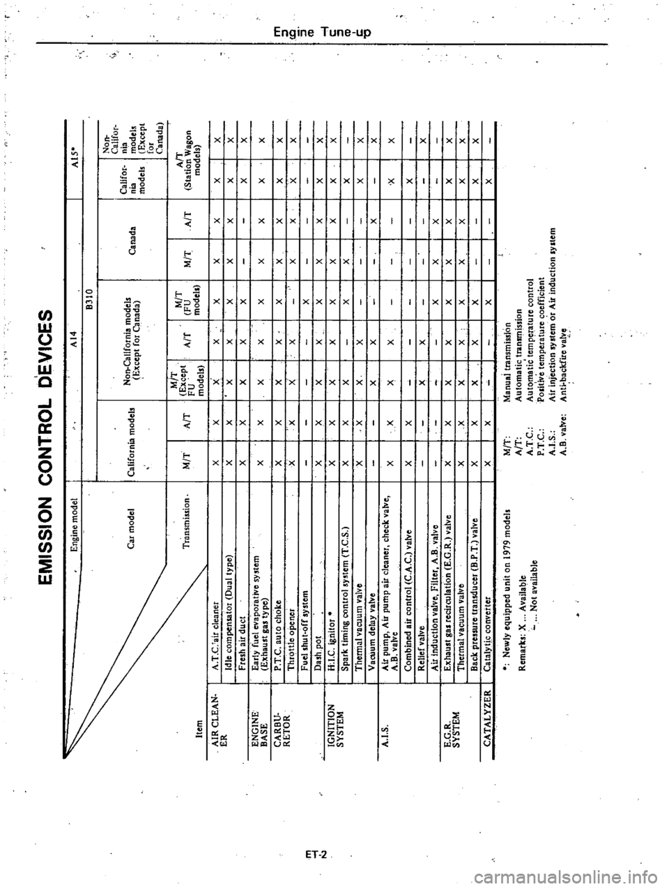
EMISSION
CONTROL
DEVICES
En
ine
model
I
AI4
I
A1S
B310
Non
CaliCor
Non
California
models
Califor
nia
Car
model
California
models
E
cept
for
C
nada
Canada
nia
modeb
models
Except
for
Canada
M
T
M
T
A
T
Ti
ansmiuion
M
T
A
T
Except
A
T
FU
M
T
A
T
Station
Wagon
FU
models
models
models
AIR
CLEAN
I
A
T
C
air
cleaner
I
X
I
X
X
I
X
I
X
I
X
I
X
I
X
X
ER
Idle
compensator
Dual
type
X
I
X
X
I
X
I
X
I
X
I
X
I
X
X
Fresh
air
duct
X
I
X
X
I
X
I
X
I
I
I
X
X
ENGINE
I
Early
fuel
evaporative
system
X
I
X
X
xl
X
I
X
I
X
I
X
X
BASE
Exhaust
gas
type
CARBV
I
P
T
C
auto
choke
X
I
X
X
X
I
X
I
X
I
X
I
X
X
m
RETOR
I
l
Thr
ttle
opener
X
X
X
X
I
I
X
I
X
I
X
X
Q
I
Fuel
shut
off
system
I
X
I
I
I
3
m
ll
i
Dash
po
t
X
X
X
X
I
X
I
X
I
X
I
X
X
N
l
IGNITION
I
H
I
C
ignitor
X
X
X
X
I
X
I
X
I
X
I
X
X
c
SYSTEM
Spark
timing
contra
system
T
e
S
X
X
X
I
I
I
I
l
X
X
I
X
ll
Thermal
vacuum
valve
X
X
X
I
X
I
I
I
I
X
X
c
Vacuum
delay
valve
X
I
X
I
I
I
X
I
0
X
A
I
S
I
Air
pump
Air
pump
air
cleaner
check
valve
I
X
X
I
X
I
X
I
I
I
I
x
X
A
B
valve
Combined
air
control
C
A
C
valve
I
X
X
I
I
I
I
I
I
X
Relief
valve
I
I
X
I
X
I
I
I
I
X
Air
induction
valve
Filter
A
B
valve
I
I
I
I
X
I
X
I
X
E
G
R
I
Exhaust
gas
recirculation
E
G
R
valve
I
X
I
X
I
X
I
X
I
X
I
X
I
X
I
X
X
SYSTEM
Thetmalvacuum
valve
I
X
I
X
I
X
I
X
I
X
I
X
I
X
I
X
X
Back
pressure
transducer
B
P
T
valve
I
X
I
X
I
X
I
X
I
X
I
I
I
X
X
CATALYZER
I
CatalytJc
converter
I
X
I
X
I
I
I
X
I
I
I
X
Newly
equipped
unit
on
1979
models
M
T
Manual
transmission
Remarks
X
Available
A
T
Automatic
transmission
Not
available
A
T
C
Aute
matic
tempeJ
ature
control
P
T
C
POlitive
temperature
coefficient
A
I
S
Air
injection
system
or
Air
induction
system
A
B
valve
Anti
backfire
valve
Page 24 of 548
make
sure
throttle
valve
operates
click
sound
is
heard
or
continuity
turns
to
OFF
when
engine
speed
decrease
to
idling
If
not
adjust
throttle
valve
switch
Fig
ET
19
AdjlUting
Throttle
V
ve
Switch
FU
models
If
throttle
valve
switch
g1f1not
be
adjusted
to
specification
replace
Engine
Tune
up
Note
If
it
is
difrlCUlt
to
judge
open
tion
of
throttle
valve
switch
by
hearing
Click
sound
caused
by
microswitch
check
as
follows
1
DiscollI
ecl
throttle
va1ve
switch
ronnector
and
connect
circuit
tester
to
throttle
va1ve
switch
2
Run
engine
under
no
load
Increase
engine
speed
slowly
and
make
sure
it
is
within
the
specified
range
when
throttle
valve
switch
is
turned
on
Then
decrease
engine
speed
slowly
and
make
sure
it
is
within
the
specified
range
when
throttle
va1ve
switch
is
turned
off
If
not
adjust
throttle
valve
switch
3
Make
sure
continuity
of
throttle
vaIve
switch
turns
to
OFF
in
the
operation
desaihed
in
step
6
Engine
operation
Engine
speed
when
throttle
valve
switch
operates
Throttle
valve
switch
continuity
When
engine
speed
increases
1
150
i200
rpm
1
000
1
200
rpm
When
engine
speed
decreases
REPLACING
FUEL
FILTER
I
Check
for
a
contaminated
filter
and
water
deposit
0
9
ET011
Fig
ET
20
Fuel
Filter
All
engines
use
a
replaceable
car
tridge
type
fuel
filter
as
an
assembly
2
Replace
fuel
filter
in
accordance
with
maintenance
schedule
OFF
ON
ON
OFF
CHECKING
FUEL
LINES
Hoses
piping
connections
etc
Check
fuel
lines
for
loose
connec
tions
cracks
and
deterioration
Re
tighten
loose
connections
and
replace
any
damaged
or
deformed
parts
REPLACING
AIR
CLEANER
FILTER
Viscous
paper
type
air
cleaner
filter
does
not
require
any
cleaning
opera
tion
until
it
is
replaced
periodically
Sushing
or
blasting
operation
will
cause
clogging
and
result
in
enrich
ment
of
carburetor
mixture
and
should
never
be
conducted
Replace
air
cleaner
filter
in
accord
ance
with
maintenance
schedule
ET
10
CHECKING
AUTOMATIC
TEMPERATURE
CONTROl
AiR
CLEANER
I
Check
that
vacuum
hoses
Intake
manifold
to
3
way
connector
3
way
connector
to
temperature
sensor
3
way
connector
to
idle
compensator
temperature
sensor
to
vacuum
motor
are
securely
connected
in
C9rrect
posi
tion
2
Check
each
hose
for
cracks
or
distortion
3
Check
A
T
C
system
for
function
by
proceeding
as
follows
ConfIrm
that
engine
is
cold
before
starting
test
With
engine
stopp
d
distonnect
fresh
air
duct
Place
a
mirror
at
the
end
of
air
c1eaner
inlet
pipe
as
shown
and
check
to
see
if
air
control
valve
is
in
correct
pOsition
2J
v
7
EF210
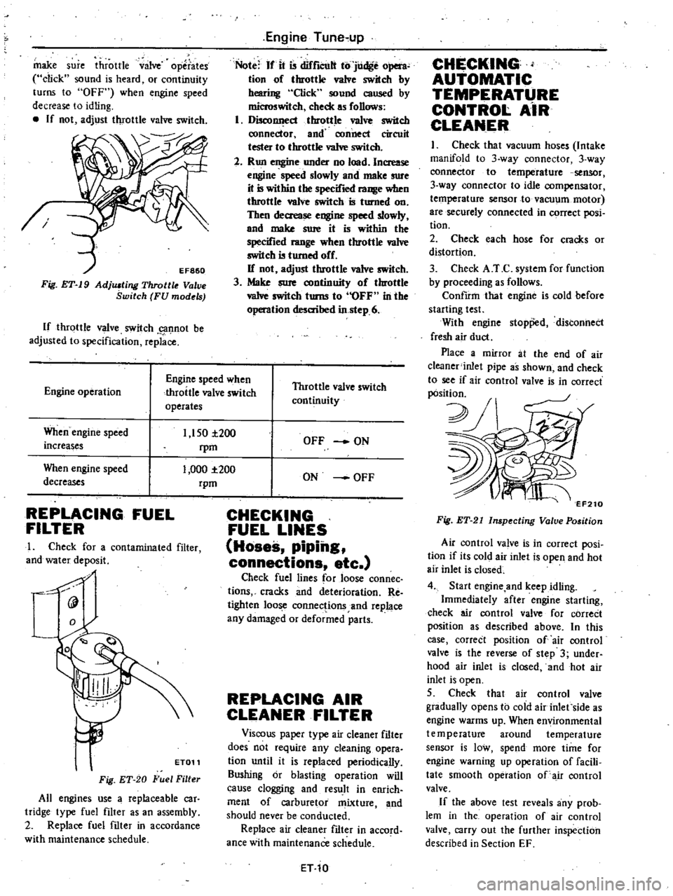
Fig
ET
21
Inspecting
Valve
Position
Air
control
va
ve
is
in
correct
posi
tion
if
its
cold
air
inlet
is
open
and
hot
air
inlet
is
closed
4
Start
engine
and
keep
idling
Immediately
after
engine
starting
check
air
control
valve
for
correCt
position
as
described
above
In
this
case
correct
position
of
air
control
valve
is
the
reverse
of
step
3
under
hood
air
inlet
is
closed
and
hot
air
inlet
is
open
5
Check
that
air
control
valve
gradually
opens
to
cold
air
inlet
side
as
engine
warms
up
When
environmental
temperature
around
temperature
sensor
is
low
spend
more
time
for
engine
warning
up
operation
of
facili
tate
smooth
operation
of
air
control
valve
If
the
above
test
reveals
any
prob
lem
in
the
operation
of
air
control
valve
carry
out
the
further
inspection
described
in
Section
EF
Page 89 of 548
TEMPERATURE
SENSOR
Removal
I
Using
pliers
flatten
clip
con
necting
vacuum
hose
to
sensor
vacuum
tube
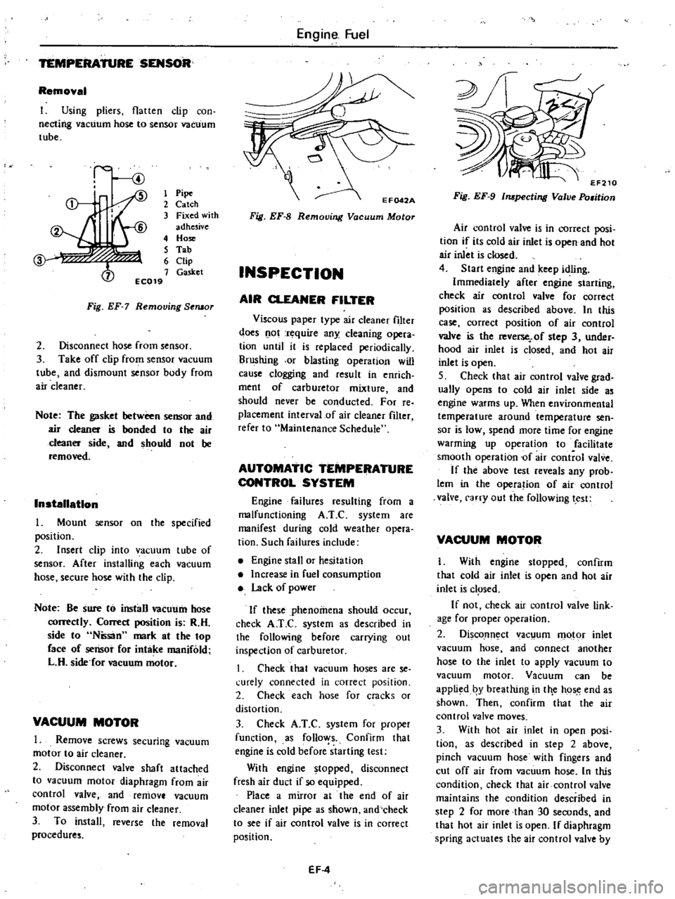
1
Pipe
2
Catch
3
Fixed
with
adhesive
4
Hose
5
Tab
6
Clip
7
Gasket
EC019
Fig
EF
7
Removing
Seruor
2
Disconnect
hose
from
sensor
3
Take
off
clip
from
sensor
vacuum
tube
and
dismount
sensor
body
from
air
cleaner
Note
The
gasket
between
sensor
and
air
cleaner
is
bonded
to
the
air
cleaner
side
and
should
not
be
removed
Installation
Mount
sensor
on
the
specified
position
2
Insert
clip
into
vacuum
tube
of
sensor
After
installing
each
vacuum
hose
secure
hose
with
the
clip
Note
Be
sure
to
install
vacUl
11n
hose
correctly
Correct
position
is
R
H
side
to
Ntisan
mark
at
the
top
face
of
sensor
for
intake
manifold
L
H
side
for
Deuum
motor
VACUUM
MOTOR
1
Remove
screws
securing
vacuum
motor
to
air
cleaner
2
Disconnect
valve
shaft
attached
to
vacuum
motor
diaphragm
from
air
control
valve
and
remove
vacuum
motor
assembly
from
air
cleaner
3
To
install
reverse
the
removal
procedures
Engine
Fuel
Fig
EF
8
Removing
Vacuum
Motor
INSPECTION
AIR
CLEANER
FILTER
Viscous
paper
type
air
cleaner
filter
does
o
ot
rt
quire
any
cleaning
opera
tion
until
it
is
replaced
periodically
Brushing
or
blasting
operation
will
cause
clogging
and
result
in
enrich
ment
of
carburetor
mixture
and
should
never
be
conducted
For
reo
placement
interval
of
air
cleaner
filter
refer
to
Maintenance
Schedule
AUTOMATIC
TEMPERATURE
CONTROL
SYSTEM
Engine
failures
resulting
from
a
malfunctioning
A
T
C
system
are
manifest
during
cold
weather
opera
tion
Such
failures
include
Engine
stall
or
hesitation
Increase
in
fuel
consumption
Lack
of
power
If
these
phenomena
should
occur
check
A
T
e
system
as
described
in
the
following
before
carrying
out
inspection
of
carburetor
I
Check
that
vacuum
hoses
are
se
l
urely
connected
in
correct
position
2
Check
each
hose
for
cracks
or
distortion
3
Check
A
T
C
system
for
proper
function
as
follo
ys
Confirm
that
engine
is
cold
before
starting
test
With
engine
topped
disconnect
fresh
air
duct
if
so
equipped
Place
a
mirror
at
the
end
of
air
cleaner
inlet
pipe
as
shown
and
check
to
see
if
air
control
valve
is
in
correct
position
EF
4
Fig
EF
9
Inspecting
Valve
Po
man
Air
control
valve
is
in
correct
posi
tion
if
its
cold
air
inlet
is
open
and
hot
air
inlet
is
closed
4
Start
engine
and
keep
idling
Immediately
after
engine
starting
check
air
control
valve
for
correct
position
as
described
above
In
this
case
correct
position
of
air
control
valve
is
the
reverse
of
step
3
under
hood
air
inlet
is
closed
and
hot
air
inlet
is
open
S
Check
that
air
control
valve
grad
ually
opens
to
cold
air
inlet
side
as
engine
warms
up
When
environmental
temperature
around
temperature
sen
sor
is
low
spend
more
time
for
engine
warming
up
operation
to
facilitate
smooth
operation
of
air
control
valve
If
the
above
test
reveals
any
prob
lem
in
the
opera
ion
of
air
control
valve
carry
out
the
following
test
VACUUM
MOTOR
I
With
engine
stopped
confirm
that
cold
air
inlet
is
open
and
hot
air
inlet
is
c1
Sed
If
not
check
air
control
valve
link
age
for
proper
operation
2
DiscoJln
ct
ac
um
motor
inlet
vacuum
hose
and
connect
another
hose
to
the
inlet
to
apply
vacuum
to
vacuum
motor
Vacuum
can
be
appli
d
by
breathing
in
tile
hos
e
end
as
shown
Then
confirm
that
the
air
control
valve
moves
3
With
hot
air
inlet
in
open
posi
tion
as
described
in
step
2
above
pinch
vacuum
hose
with
fingers
and
cut
off
air
from
vacuum
hose
In
this
condition
check
that
air
control
valve
maintains
the
condition
described
in
step
2
for
more
than
30
seconds
and
that
hot
air
inlet
is
open
If
diaphragm
spring
actuates
the
air
control
valve
by
Page 91 of 548
Engine
Fuel
S
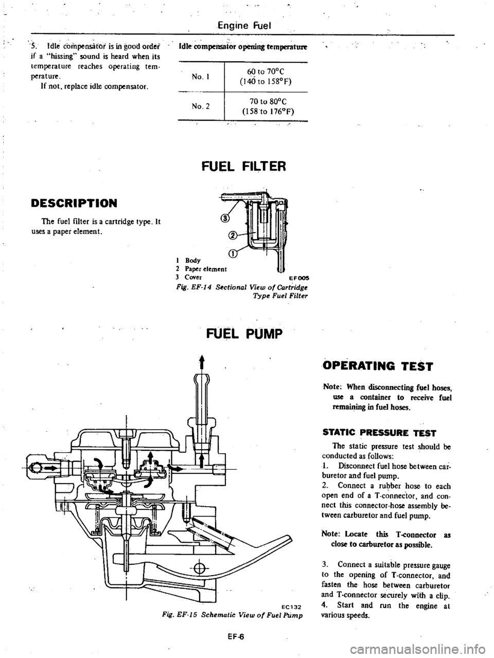
Idle
compensator
is
ill
good
order
if
a
hissing
sound
is
heard
when
its
temperature
reaches
operating
tern
perature
If
not
replace
idle
compensator
ldlerompensator
l
b
l
r
I
No
1
60
to
700C
140
to
15
Of
No
2
70
to
800C
158
to
1760F
FUEL
FILTER
DESCRIPTION
t
t
I
J
i
l
The
fuel
filter
is
a
cartridge
type
It
useS
a
paper
element
1
Body
2
Paper
element
3
Cover
EFOOS
Fig
EF
14
Sectional
View
of
Cartridge
Type
FuelFilte
FUEL
PUMP
t
j
f
EC132
Fig
EF
15
Schematic
View
of
Fuel
Pump
EF
6
OPERATING
TEST
Note
When
disconnecting
fuel
hoses
me
a
container
to
receive
fuel
remaining
in
fuel
hoses
STATIC
PRESSURE
TEST
The
static
pressure
test
should
be
conducted
as
follows
I
Disconnect
fuel
hose
between
car
buretor
and
fuel
pump
2
Connect
a
rubber
hose
to
each
open
end
of
aT
connector
and
con
nect
this
connector
hose
assembly
be
tween
carburetor
and
fuel
pump
Note
Locate
this
T
eonnector
as
close
to
carburetor
as
possible
3
Connect
a
suitable
pressure
gauge
to
the
opening
of
T
connector
and
fasten
the
hose
between
carburetor
and
T
connector
secUrely
with
a
clip
4
Start
and
run
the
engine
at
various
speeds
Page 93 of 548
DESCRIPTION
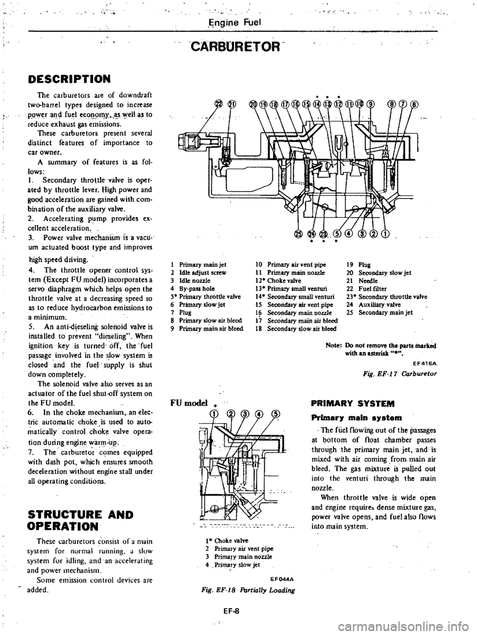
The
carburetors
are
of
downdraft
two
barrel
type
designed
to
increase
ppwe
r
a
fu
l
eC
l
Il
Y
t
3
ell
a
to
reduce
exhaust
gas
emissions
These
carburetors
present
several
distinct
features
of
importance
to
car
owner
A
summary
of
features
is
as
fol
lows
1
Secondary
throttle
valve
is
oper
ated
by
throttle
lever
High
power
and
good
acceleration
are
gained
with
com
bination
of
the
auxiliary
valve
2
Accelerating
pump
provide
ex
cellent
acceleration
3
Power
valve
mechanism
is
a
vacuo
urn
actuated
boost
type
and
improves
high
speed
driving
4
The
throttle
opener
control
sys
tem
Except
FU
model
incorporates
a
servo
diaphragm
which
helps
open
the
throttle
valve
at
a
decreasing
speed
so
as
to
reduce
hydrocarbon
emissions
to
a
minimum
5
An
anti
d
eseling
solenoid
valve
is
installed
to
prevent
dieseling
When
ignition
key
is
turned
off
the
fuel
passage
involved
in
the
ow
system
is
closed
and
the
fuel
supply
is
shut
down
completely
The
solenoid
valve
also
serves
as
an
actuator
of
the
fuel
shut
off
system
on
the
FU
model
6
In
the
choke
mechanism
an
elec
trie
automatic
choke
is
used
to
auto
maticaDy
control
chok
valve
opera
tion
during
engin
war
up
7
The
carburetor
comes
equipped
with
dash
pot
which
ensures
smooth
deceleration
without
engine
stall
under
aU
operating
conditions
STRUCTURE
AND
OPERATION
These
carburetors
consist
of
a
main
system
for
normal
running
a
slow
system
for
idling
and
an
accelerating
and
power
mechanisIll
Some
emission
control
devices
are
added
E
ngine
Fuel
CARBURETOR
I
J
1
Primary
main
jet
2
Idle
adjust
screw
3
hUe
nozzle
4
By
pass
hole
5
Primary
throttle
valve
6
Primary
slow
jet
7
ptug
8
Primary
5l
w
air
bleed
9
Primary
main
air
bleed
10
Primary
air
vent
pipe
11
Primuy
main
nozzle
12
Choke
valve
13
Primary
small
venturi
14
Secondary
small
venturi
15
Secondary
air
vent
pipe
16
Secondary
main
nozzle
17
Secondary
main
air
bleed
18
Secondary
slow
air
bleed
1
Oloke
valve
2
Primary
air
vent
pipe
3
Prima
y
main
nozzle
4
Primary
slow
jet
19
Plug
20
Secondary
slow
jet
21
Needte
22
Fuel
fLlter
23
Secondary
tIuottle
valve
24
Auxiliary
valve
25
Secondary
main
jet
Note
Do
not
remo
the
parts
inarbd
with
anuteriak
EF416A
Fig
EF
17
Carburetor
PRIMARY
SYSTEM
PrlinarJ
main
sJstam
The
fUel
flowing
out
of
the
passages
at
bottom
of
float
chamber
passes
through
the
primary
main
jet
and
is
mixed
with
air
coming
from
main
air
bleed
The
gas
mixture
is
pulled
out
into
the
venturi
through
the
main
nozzle
When
throttle
valve
is
wide
open
and
engine
require
dense
mixture
gas
power
valve
opens
and
fuel
also
flows
into
main
system
EF044A
Fig
EF
18
PtJrlially
Loading
EF
8
Page 94 of 548
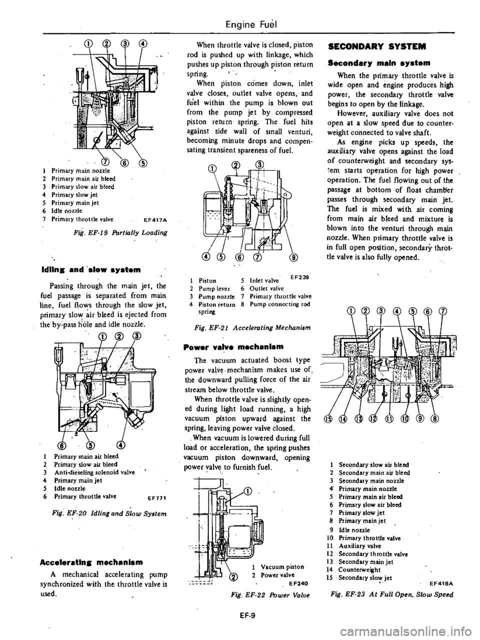
t
1
Primary
main
nozzle
2
Primary
main
air
bleed
3
Primary
slow
air
bleed
4
Primary
slow
jet
5
Primary
main
jet
6
Idle
nozzle
7
Primary
throttle
valve
EF417A
Fig
EF
I9
Portially
Loading
IdUns
nd
slow
system
Passing
through
the
main
jet
the
fuel
passage
is
separated
from
main
line
fuel
flows
through
the
slow
jet
primary
slow
air
bleed
is
ejected
from
the
by
pass
hole
and
idle
nozzle
cp
v
Ii
l
1
Primary
main
air
bleed
2
Primary
slow
air
bleed
3
Anti
fieseling
solenoid
valve
4
Primary
main
jet
5
Idle
nozzle
6
Primary
throttle
valve
EF711
Fig
EF
20
Idling
and
Slow
System
Aceeler
tlns
meeh
nlsm
A
mechanical
accelerating
pump
synchronized
with
the
throttle
valve
is
used
Engine
Fuel
When
throttle
valve
is
closed
piston
rod
is
pushed
up
wi
th
linkage
which
pushes
up
piston
through
piston
return
spring
When
piston
comes
down
inlet
valve
closes
outlet
valve
opens
and
fuel
within
the
pump
is
blown
out
from
the
pump
je
t
by
compressed
piston
return
spring
The
fuel
hits
against
side
wall
of
small
venturi
becoming
minute
drops
and
compen
sating
transient
spareness
of
fuel
1
r
@
CD
V
1
Piston
2
Pump
lever
3
Pump
nozzle
4
Piston
return
spring
5
Inlet
valve
EF239
6
Outlet
valve
7
Primary
throttle
valve
8
Pump
connecting
rod
Fig
EF
21
Accelerating
Mechani
m
Power
v
lve
meeh
nlsm
The
vacuum
actuated
boost
type
power
va
v
mechanism
makes
use
of
the
downward
pulling
force
of
the
air
stream
below
throttle
valve
When
throttle
valve
is
slightly
open
ed
during
light
load
running
a
high
vacuum
p
ston
upward
against
the
spring
leaving
power
valve
closed
When
vacuum
is
lowered
during
full
load
or
acceleration
the
spring
pushes
vacuum
piston
downward
opening
power
valve
to
furnish
fuel
I
t
f
i
1
Vacuum
piston
2
Power
valve
EF240
Fig
EF
22
Power
Valve
EF
9
SECONDARY
SYSTEM
Second
ry
m
ln
system
When
the
primary
throttle
valve
is
wide
open
and
engine
produces
high
power
the
secondary
throttle
valve
begins
to
open
by
the
linkage
However
auxiliary
valve
does
not
open
at
a
slow
speed
due
to
counter
weight
connected
to
valve
shaft
As
engine
picks
up
speeds
the
auxiliary
valve
opens
against
the
load
of
counterweight
and
secondary
sys
em
starts
operation
for
high
power
operation
The
fuel
flowing
out
of
the
passage
at
bottom
of
float
chamt
er
passes
through
secondary
main
jet
The
fuel
is
mixed
wi
th
air
coming
from
main
air
bleed
and
mixture
is
blown
in
to
the
venturi
through
main
nozzle
When
primary
throttle
valve
is
in
full
open
position
secondary
throt
tle
valve
is
also
fully
opened
I
Secl
ndary
slow
air
bleed
2
Secondary
main
air
bleed
3
Secondary
main
nozzle
4
Primary
main
nozzle
5
Primary
main
air
bleed
6
Primary
slow
air
bleed
7
Primary
slow
jet
8
Primary
main
jet
9
Idle
nozzle
10
Primary
throttle
valve
11
Auxiliary
valve
12
Secondary
throttle
valve
13
Secondary
main
jet
14
Counterweight
15
Secondary
slow
jet
EF418A
Fig
EF
23
At
Full
Open
Stow
Speed
Page 95 of 548
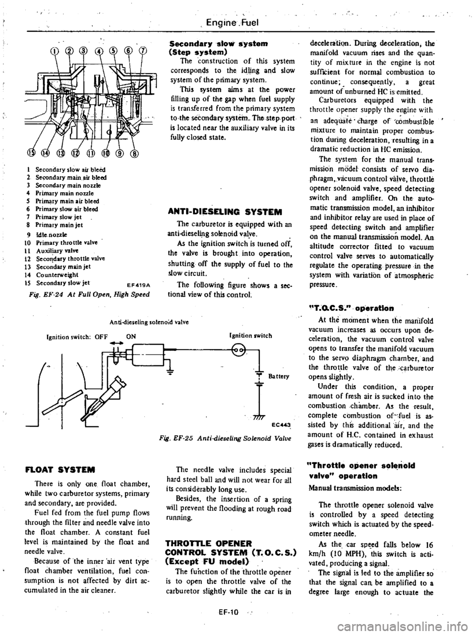
I
Secondary
slow
air
bleed
2
Secondary
main
air
bleed
3
Secondary
main
nozzle
4
Primary
main
nozzle
5
Primary
main
air
bleed
6
Primary
slow
air
bleed
7
Primary
slow
jet
8
Primary
main
jet
9
Idle
nozzle
10
Primary
throttle
valve
II
Auxiliary
valve
12
Seco
dary
throttle
valve
13
Secondary
main
jet
14
Counterweight
IS
Secondary
slow
jet
EF419A
Fig
EF
24
At
Full
Open
High
Speed
Engine
Fuel
Secondary
slow
system
Step
system
The
construction
of
this
system
corresponds
to
the
idling
and
slow
system
of
the
primary
system
This
system
aims
at
the
power
filling
up
of
the
gap
when
fuel
supply
is
transferred
from
the
primary
system
to
the
secondary
system
The
stepport
is
located
near
the
auxiliary
valve
in
its
fully
closed
state
ANTI
DIESELING
SYSTEM
The
carburetor
is
equipped
with
an
anti
liese1i
lg
solenoid
valye
As
the
ignition
switch
is
turned
off
the
valve
is
brought
into
operation
shutting
off
the
supply
of
fuel
to
the
slow
circuit
The
following
figure
shows
a
see
tional
view
of
this
control
An
ti
dies
eling
solenoid
valve
Ignition
switch
OFF
ON
t
L
li
FLOAT
SYSTEM
There
is
only
one
float
chamber
while
two
carburetor
systems
primary
and
secondary
are
provided
Fuel
fed
from
the
fuel
pump
flows
through
the
filter
and
needle
valve
into
the
float
chamber
A
constant
fuel
level
is
maintained
by
the
float
and
needle
valve
Because
of
the
inner
air
vent
type
float
chamber
ventilation
fuel
con
sumption
is
not
affected
by
dirt
ac
cumulated
in
the
air
cleaner
Ignition
switch
Q
1
T
Battery
niT
EC
3
Fig
EF
25
Anti
dieseling
Solenoid
Valve
The
needle
valve
includes
special
hard
steel
ball
and
wiD
not
wear
for
all
its
considerably
long
use
Besides
the
insertion
of
a
spring
will
prevent
the
flooding
at
rough
road
running
THROTTLE
OPENER
CONTROL
SYSTEM
T
O
C
S
Except
FU
model
The
function
of
the
throttle
opener
is
to
open
the
throttle
valve
of
the
carburetor
slightly
while
the
car
is
in
EF
10
deceleration
During
deceleration
the
manifold
vacuum
rises
and
the
quan
tity
of
mixture
in
the
engine
is
not
suffICient
for
normal
combustion
to
continue
4
consequently
a
great
amount
of
unburned
HC
is
emitted
Carburetors
equipped
with
the
throttle
opener
supply
the
engine
with
an
adequate
charge
of
combustible
mixture
to
maintain
proper
combus
tion
during
deceleration
resulting
in
a
dramatic
reduction
in
HC
emission
The
system
for
the
manual
trans
mission
model
consists
of
servo
dia
phragm
vlicuum
control
valve
throttle
opener
solenoid
valve
spee
l
detecting
switch
and
amplifier
On
the
auto
matic
transmission
model
an
inhibitor
and
inhibitor
relay
are
used
in
place
of
speed
detecting
switch
and
amplifier
on
the
manual
transmission
model
An
altitude
corrector
fitted
to
vacuum
control
valve
serves
to
automatically
regulate
the
operating
pressure
in
the
system
with
variation
of
atmospheric
pressure
T
o
C
S
n
operatIon
At
the
moment
when
the
manifold
vacuum
increases
as
occurs
upon
de
celeration
the
vacuum
control
valve
opens
to
transfer
the
manifold
vacuum
to
the
servo
diaphragm
chamber
and
the
throttle
valve
of
the
carburetor
opens
slightly
Under
this
condition
a
proper
amount
of
fresh
air
is
sucked
into
the
combustion
chamber
As
the
result
complete
combustion
of
fuel
is
as
sisted
by
this
additional
air
and
the
amount
of
H
C
contained
in
exhaust
gases
is
dramatically
reduced
Throttle
Clpener
sol
nold
valve
operation
Manual
transmission
models
The
throttle
opener
solenoid
valve
is
controlled
by
a
speed
detecting
switch
which
is
actuated
by
the
speed
ometer
needle
As
the
car
sp
ed
falls
below
16
km
h
10
MPH
this
switch
is
acti
vated
producing
a
signal
The
signal
is
led
to
the
amplifier
so
that
the
signal
can
be
amplified
to
a
degree
large
enough
to
actuate
the
Page 98 of 548
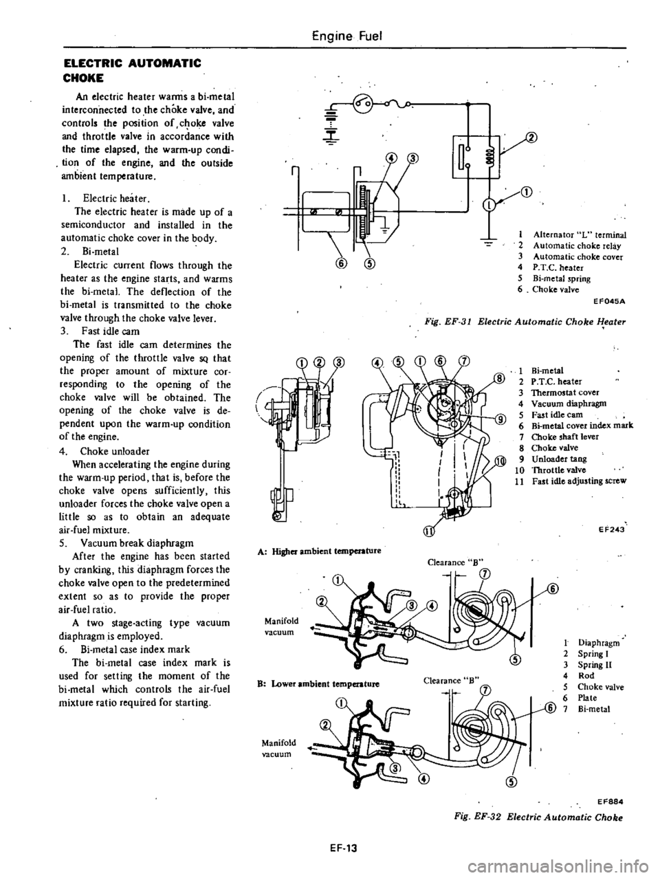
ELECTRIC
AUTOMATIC
CHOKE
An
electric
heater
warms
a
bi
metal
interconnected
to
the
choke
valve
and
controls
the
position
of
c
oke
valve
and
throttle
valve
in
accordance
with
the
time
elapsed
the
warm
up
condi
tion
of
the
engine
and
the
outside
ambient
temperature
Electric
heater
The
electric
heater
is
made
up
of
a
semiconductor
and
installed
in
the
automatic
choke
cover
in
the
body
2
Bi
metal
Electric
current
flows
through
the
heater
as
the
engine
starts
and
warms
the
bi
metal
The
deflection
of
the
bi
metal
is
transmitted
to
the
choke
valve
through
the
choke
valve
lever
3
Fast
idle
cam
The
fast
idle
cam
determines
the
opening
of
the
throttle
valve
SQ
that
the
proper
amount
of
mixture
cor
responding
to
the
opening
of
the
choke
valve
will
be
obtained
The
opening
of
the
choke
valve
is
de
pendent
upon
the
warm
up
condition
of
the
engine
4
Choke
unloader
When
accelerating
the
engine
during
the
warm
up
period
that
is
before
the
choke
valve
opens
sufficiently
this
unloader
forces
the
choke
valve
open
a
little
so
as
to
obtain
an
adequate
air
fuel
mixture
S
Vacuum
break
diaphragm
After
the
engine
has
been
started
by
cranking
this
diaphragm
forces
the
choke
valve
open
to
the
predetermined
extent
so
as
to
provide
the
proper
air
fuel
ratio
A
two
stage
acting
type
vacuum
diaphragm
is
employed
6
Si
metal
case
index
mark
The
bi
metal
case
index
mark
is
used
for
selling
the
moment
of
the
bi
metal
which
controls
the
air
fuel
mixture
ratio
required
for
starting
Engine
Fuel
r
m
2
3
4
5
6
r
3
1
@
@
Alternator
L
terminal
Automatic
choke
relay
Automatic
choke
cover
P
T
C
heater
Bi
metaJ
spring
Choke
valve
Fig
EF
31
Electric
Automatic
Choke
l
eater
EF045A
l
A
Higher
ambient
temperature
Manifold
vacuum
Clearance
B
B
Lower
ambient
temperature
Clearance
Manifold
vacuum
1
Hi
metal
2
P
T
e
heater
3
Thermostat
cover
4
Vacuum
diaphragm
5
Fast
idle
earn
6
Bi
metal
cover
index
mark
7
Choke
shaft
lever
8
Choke
valve
9
Unloader
tang
10
Throttle
valve
11
Fast
idle
adjusting
screw
EF243
t
Diaphragm
2
Spring
I
3
Spring
11
4
Rod
5
Choke
valve
6
Plate
@
7
Bi
metal
EF884
Fig
EF
32
Electric
Automatic
Choke
EF
13
Page 105 of 548
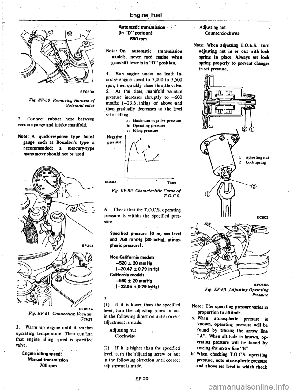
EF053A
Fig
EF
50
Removing
JWrneu
of
Solenoid
valve
2
Connect
rubber
hose
between
vacuum
gauge
and
intake
manifold
Note
A
quick
response
type
boost
gauge
such
as
Bourdon
s
type
is
recommended
a
mercury
type
manometer
should
not
be
used
3
Warm
up
engine
until
it
reaches
operating
temperature
Then
confirm
that
engine
idling
speed
is
specified
valve
Engine
idling
speed
Manual
transmission
700
rpm
Engine
Fuel
Automatic
transmission
in
0
position
650rpm
Note
On
automatic
transmission
models
never
race
engine
when
gearshift
lever
is
in
0
position
4
Run
engine
under
no
load
In
crease
engine
speed
to
3
000
to
3
500
rpm
then
quickly
close
throttle
valve
S
At
the
time
manifold
vacuum
pressure
increases
abruptly
to
600
rnmHg
23
6
inHg
or
above
and
then
gradually
decreases
to
the
level
set
at
idling
a
Maximum
negative
pressure
b
Operating
pressure
c
Idling
pressure
Nega
ive
pressure
EC502
Time
Fig
EF
52
Characteristic
Curve
of
T
O
C
S
6
Check
that
the
T
O
C
s
operating
pressure
is
within
the
specified
pres
sure
Specified
pressure
0
m
sea
level
end
760
mmHg
30
inHgl
atmOs
pheric
pressure
Non
Califomia
models
520
20
mmHg
20
47
0
79
inHg
California
models
560
20
mmHg
22
05
9
79
inHgl
7
I
If
it
is
lower
than
the
specified
level
turn
the
adjusting
screw
or
nut
in
the
following
direction
until
correct
adjustment
is
made
Adjusting
nut
Clockwise
2
If
it
is
higher
than
the
specified
levei
turn
the
adjusting
screw
or
nut
in
the
following
direction
until
correct
adjustment
is
made
EF
20
Adjusting
nut
Counterclockwise
Note
When
adjusting
T
O
C
S
turn
adjusting
nut
in
or
out
with
lock
spring
in
place
Always
set
lock
spring
properly
to
prevent
changes
in
set
pressure
Vo
1
Adjusting
nut
2
Lock
spring
n
EC802
EF055A
Fig
EF
53
Adjusting
Ope
llting
Pre
3ure
Note
The
operating
pressure
varies
in
proportion
to
altitude
a
When
atmospheric
pressure
is
known
operating
pressure
will
be
found
by
tracing
the
arrow
line
A
When
altitude
is
known
op
erating
pressure
will
be
found
by
tracing
the
arrow
line
B
b
When
checking
T
O
C
S
operating
pressure
note
atmospheric
pressure
and
above
sea
level
in
which
check