height DATSUN 210 1979 Service Manual
[x] Cancel search | Manufacturer: DATSUN, Model Year: 1979, Model line: 210, Model: DATSUN 210 1979Pages: 548, PDF Size: 28.66 MB
Page 26 of 548
R
EPIACING
AIR
PUMP
AIR
CLEANER
FILTER
Except
FU
models
and
Canada
models
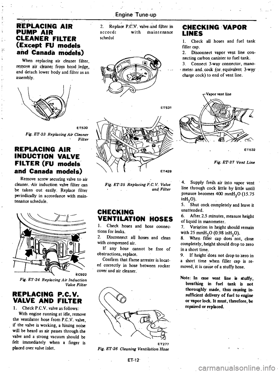
When
replacing
air
cleaner
filter
remove
ir
cleane
frO
ho
od
legge
and
detach
lower
body
and
filter
as
an
assembly
ET530
Fig
ET
23
Replacing
Air
Cleaner
Filter
REPI
ACINGAIR
INDUCTION
VALVE
FILTER
FU
models
and
Canada
models
Remove
screw
securirtg
valve
to
air
cleaner
Air
induction
valve
fIlter
can
be
taken
out
easily
Replace
fIlter
periodically
in
accordance
with
main
tenance
schedule
2
C
l
11
l
r
r
EC9
Fig
ET
24
R
pklcing
Air
Induction
Value
Filter
REPLACING
P
C
V
VALVEANb
FILTER
I
Check
P
C
V
valve
as
follows
With
engine
running
at
idle
remove
the
ventilator
hose
from
P
C
V
valve
if
the
valve
is
working
a
hissing
noise
will
be
heard
as
air
passes
through
the
valve
and
a
strong
vacuum
should
be
felt
inunediately
when
a
finger
is
placed
over
valve
inlet
Engine
Tune
up
2
Replace
P
C
V
Valve
and
filter
in
accord
with
maintenance
schedul
ET531
Fig
ET
25
Replacing
P
C
V
Value
and
Filter
CHECKING
VENTILATION
HOSES
I
Check
hoses
and
hose
connec
tions
for
leaks
2
Disconnect
all
hoses
and
clean
with
compressed
air
If
any
hose
cannot
be
free
of
obstructions
replace
Confirm
that
flame
arrester
is
locat
ed
correctly
in
hose
between
rocker
cover
and
air
cleaner
ET277
Fig
ET
26
Cleaning
Ventilation
Hose
ET
12
CHECKING
VAPOR
LINES
I
Check
all
hoses
and
fuel
tank
flller
cap
2
Disconnect
vapor
vent
line
con
necting
carbon
canister
to
fuel
tank
3
Connect
3
way
connector
mana
meter
and
cock
or
equivalent
3
w
y
charge
cock
to
end
of
vent
line
ET532
Fig
ET
27
Vent
Line
4
Supply
fresh
air
into
vapor
vent
line
through
cock
little
by
little
until
pressure
become
400
mmH20
is
75
inH20
5
Shut
cock
completely
and
leave
it
unatiended
6
After
2
5
minutes
measure
height
of
liquid
in
manometer
7
Varilllion
in
height
should
remain
with
25
mmHp
0
98
inH20
8
When
filler
cap
does
not
close
completely
height
should
drop
to
zero
ih
a
short
time
9
If
height
does
not
drop
to
zero
in
a
short
time
when
filler
cap
is
re
moved
it
is
cause
of
a
stuffy
hose
Note
In
case
vent
tine
B
stuffy
breathing
in
fuel
tank
is
not
thoroughly
made
thlis
caming
in
sufficient
delivery
of
fuel
to
engine
or
vapor
lock
It
must
tberefore
be
repaired
or
replaced
Page 51 of 548
9
Make
SUre
there
is
proper
end
play
at
crankshaft
Crankshaft
end
play
0
05toO
15mm
0
OO20
to
0
0059
in
laJlk
h
end
play
J
EM486
Fig
EM
63
Checking
Crank
luJft
End
Play
10
Install
rear
oil
seal
using
suitable
drift
Fig
EM
64
n
talling
Rear
Oil
Seal
II
Install
rear
plate
12
Install
flywh
el
secwely
and
tighten
bolts
to
specified
torque
dl
Tightening
torque
Flywheel
and
drive
plate
A
14
engine
fixing
bolts
8
0
to
9
0
kg
m
58
to
65
ft
Ib
Drive
plate
A
15
engine
fixing
bolts
8
5
to
9
5
kg
m
61
to
69
ft
b
Fig
EM
65
n
talling
Flywheel
13
Rotate
engine
quarter
turn
and
install
piston
rod
assembly
using
Pis
Engine
Mechanical
ton
Ring
Compressor
EM03470000
EM497
Fig
EM
66
tolling
Platon
Rod
Assem
bly
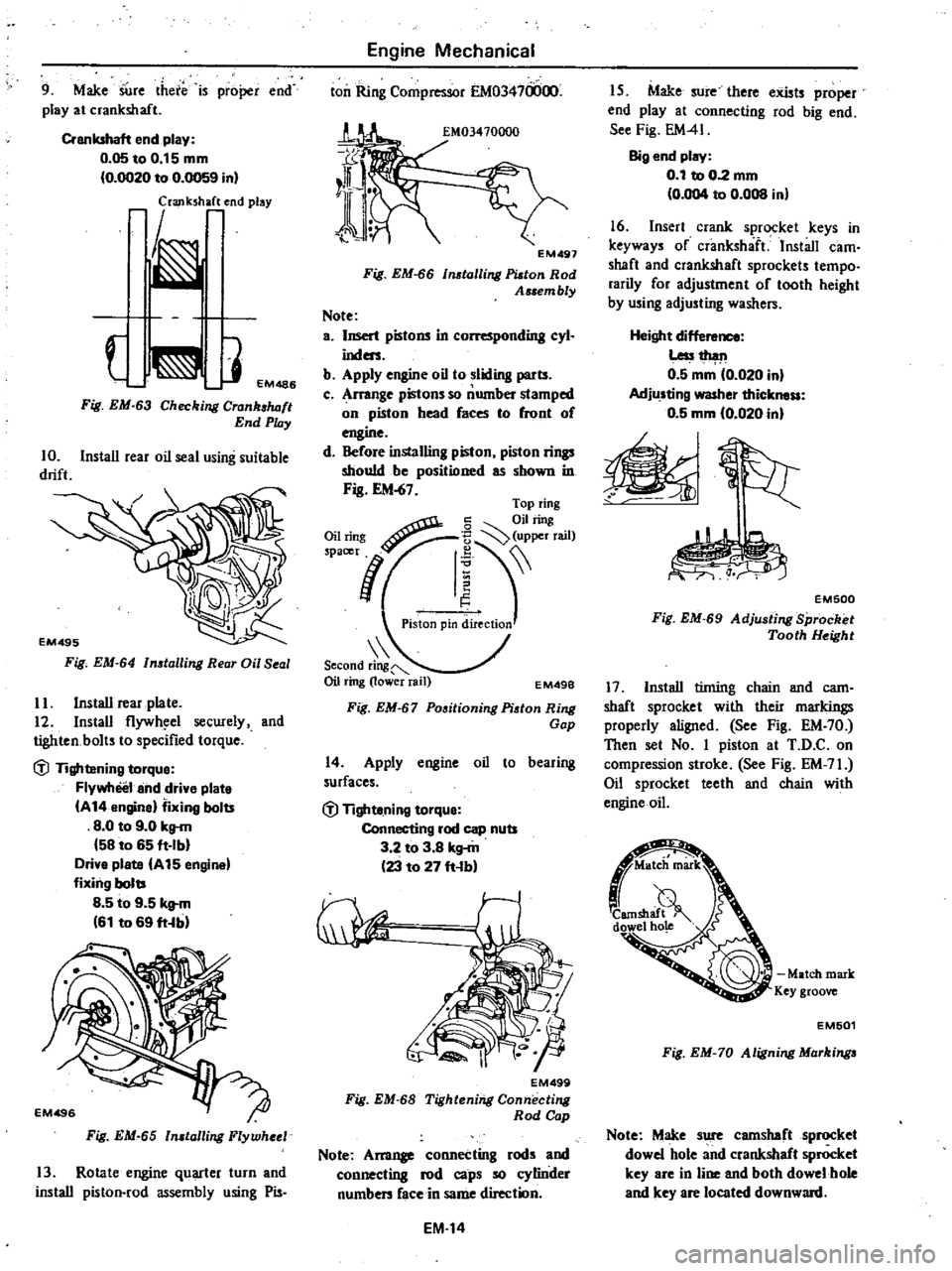
Note
a
Insert
pistons
in
L
r
nding
cyl
inders
b
Apply
engine
oil
to
sliding
parts
c
Arrange
pistons
so
number
stamped
on
piston
head
faces
to
front
of
engine
d
Before
installing
piston
piston
rings
should
be
positioned
as
shown
in
Fig
EM
67
Second
ring
Oil
ring
lower
rail
EM49B
Fig
EM
67
Positioning
Piston
Ring
Gap
14
Apply
engine
oil
to
bearing
surfaces
dl
Tighte
ning
torque
Connecting
rod
cap
nuts
3
2
to
3
8
kg
m
23
to
27
ft
b
EM499
Fig
EM
68
Tightening
Connecting
Rod
Cap
Note
Am11
connecting
rods
and
connecting
rod
caps
so
cylinder
numben
face
in
same
direction
EM
14
I
S
Make
sure
there
exists
proper
end
play
at
connecting
rod
big
end
See
Fig
EM41
Big
end
play
0
1
to
0
2
mm
0
004
to
0
008
in
16
Insert
crank
sprocket
keys
in
keyways
of
crankshaft
Install
cam
shaft
and
crankshaft
sprockets
tempo
rarily
for
adjustment
of
tooth
height
by
using
adjusting
washers
Height
dif
Less1
h
l11
0
5
mm
0
020
in
Adjusting
washer
thickness
0
5
mm
10
020
in
EM500
Fig
EM
69
Adju
ting
Sprocket
Tooth
Height
17
Install
tinting
chain
and
cam
shaft
sprocket
with
their
markings
properly
aligned
See
Fig
EM
70
Then
set
No
I
piston
at
T
D
C
on
compression
stroke
See
Fig
EM
71
Oil
sprocket
teeth
and
chain
with
engine
oil
Match
mark
Key
groove
EM501
Fig
EM
70
Aligning
Markinga
Note
Make
sure
camshaft
sprocket
dowel
hole
and
crankshaft
sprocket
key
are
in
line
and
both
dowel
hole
and
key
are
located
downward
Page 56 of 548
Engine
Mechanical
INSPECTION
AND
ADJUSTMENT
CYLINDER
HEAD
AND
VALVE
Cylinder
head
Unit
mm
in
Standard
Limit
Head
surface
flatness
Less
than
0
05
0
0020
0
1
0
004
Valve
Unit
mm
in
j
I
Hot
Valve
clearance
I
Cold
Intake
valve
Exhaust
valve
0
35
0
014
0
25
0
010
Valve
lift
7
91
0
3114
8
22
0
3236
H
37
0
to
37
2
1
457
to
1
465
30
0
to
30
2
1
181
to
1
189
D
L
Valve
head
diameter
a
H
Valve
length
L
103
6
to
104
0
4
079
to
4
094
D
7
970
to
7
985
0
3138
to
0
3144
7
945
to
7
960
0
3128
to
0
3134
Valve
stem
diameter
EM769
Valve
seat
angle
a
45030
Valve
spring
Free
height
mm
in
46
5
1
831
Compressed
height
mm
kg
in
lb
30
2
22
2
to
25
6
valve
open
1
189
49
0
to
56
4
Assembled
height
mm
kg
in
lh
38
7
544
to
62
6
valve
closed
1
524
120
0
to
138
0
Out
of
square
S
mm
in
Less
than
1
6
0
063
EM
19
Page 62 of 548

Engine
Mechanical
Camshaft
specifications
Valve
timing
Standard
Camshaft
bend
Less
than
oms
0
0006
Intake
36
200
to
36
250
I
4252
to
I
4272
Carn
height
Exhaust
36
930
to
36
980
I
4539
to
I
4559
5
65
0
2224
Intake
Cam
lobe
lift
I
Exhaust
5
92
0
2331
Difference
in
diameter
max
worn
and
min
worn
parts
of
camshaft
journal
0
03
to
0
07
0
0012
to
0
0028
Camshaft
end
play
om
to
0
05
0
0004
to
0
0020
ff
fif
ff
s
D
C
EM120
Unit
degree
a
b
248
d
e
c
14
54
20
256
EM
25
Unit
mm
in
Wear
repair
limit
0
05
0
0020
35
700
I
4055
36
430
1
4342
0
10
0
0039
0
10
0
0039
f
56
Page 83 of 548
10
Replenish
coolant
and
check
for
leaks
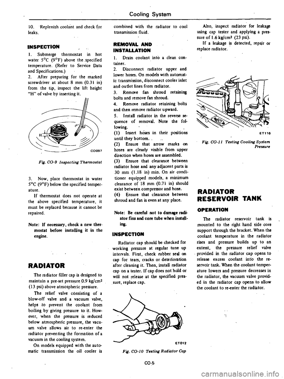
INSPECTION
I
Submerge
thermostat
in
hot
water
SOC
90F
above
the
specified
temperature
Refer
to
Service
Data
and
Specifications
2
After
preparing
for
the
marked
screwdriver
at
about
8
mm
0
31
in
from
the
tip
inspect
the
lift
height
H
of
valve
by
inserting
it
f
C0097
Fig
CO
g
In
pecting
Thermostat
3
Now
place
thermostat
in
water
SoC
90F
below
the
specified
temper
ature
If
thermostat
does
not
operate
at
the
above
specified
temperature
it
must
be
replaced
because
it
cannot
be
repaired
Note
If
necessary
check
a
new
ther
mostat
before
installing
it
in
the
engine
RADIATOR
The
radiator
filler
cap
is
designed
to
maintain
a
pre
set
pressure
0
9
kgfcm2
13
psi
above
atmospheric
pressure
The
relief
valve
consisting
of
a
blow
off
valve
and
a
vacuum
valve
helps
to
prevent
the
coolant
from
boiling
by
giving
pressure
to
it
How
ever
when
the
pressure
is
reduced
below
atmospheric
pressure
the
vacu
wn
valve
allows
air
to
re
enter
the
radiator
preventing
the
formation
ofa
vacuum
in
the
cooling
system
On
models
equipped
wi
th
the
au
to
malic
transmission
the
oil
cooler
is
Cooling
System
combined
with
the
radiator
to
cool
transmission
fluid
REMOVAL
AND
INSTALLATION
1
Drain
coolant
into
a
clean
con
tainer
2
Disconnect
radiator
upper
and
lower
hoses
On
models
with
automat
ic
transmission
disconnect
cooler
inlet
and
ou
tlet
lines
from
radiator
3
Rem
Ne
fan
shroud
retaining
bolts
and
remove
fan
shroud
4
Remove
radiator
retaining
bolts
and
then
remove
radiator
upward
S
I
nstaD
radiator
in
the
reverse
se
quence
of
removal
Note
the
fol
lowing
I
Insert
hoses
in
their
positions
until
they
bottom
2
Ensure
that
arrow
marks
on
hoses
are
clearly
visible
from
upper
direction
when
hoses
are
assembled
3
Ensure
that
clearance
between
radiator
hose
and
any
adjacent
parts
is
30
mm
1
18
in
min
On
air
condi
tioner
equipped
models
a
minimum
clearance
of
18
mm
0
71
in
should
exist
between
compressor
and
hose
4
Ensure
that
clearance
be
tween
shroud
and
fan
is
even
at
any
place
Note
Be
careful
not
to
damage
radi
ator
fins
and
core
tube
when
install
ing
INSPECTION
Radiator
cap
should
be
checked
for
working
pressure
at
regular
tune
up
intelVals
First
check
rubber
seal
on
cap
for
tears
cracks
or
deteriontion
after
cleaning
it
Then
ins
taD
radiator
cap
on
a
tester
If
cap
does
not
hold
or
will
not
release
at
the
specified
pres
sure
replace
cap
Fig
CO
lO
Testing
Radiator
Cap
CO
5
Also
inspect
radiator
for
leakage
using
cap
tester
and
applying
a
pres
sure
of
1
6
kgfcm2
23
psi
If
a
leakage
is
detected
repair
or
replace
radiator
ET116
Fig
CO
II
Testing
Cooling
System
Prtuurt
RADIATOR
RESERVOIR
TANK
OPERATION
The
radiator
reservoir
tank
is
mounted
to
the
right
hand
side
core
support
through
the
bracket
When
the
coolant
temperature
in
the
radiator
rises
and
pressure
builds
up
to
an
extent
the
pressure
relief
valve
provided
in
the
radiator
cap
opens
to
release
excess
coolant
into
the
re
servoir
tank
When
the
coolant
temper
ature
lowers
and
pressure
decreases
in
the
radiator
the
vacuum
valve
provid
ed
in
the
radiator
cap
opens
to
allow
the
coolant
to
re
enter
the
radiator
Page 155 of 548

OPERATION
Fuel
vapors
from
the
sealed
fuel
tank
are
led
into
the
carbon
canister
The
canister
is
filled
with
activated
charcoals
to
absorb
the
fuel
vapors
when
the
engine
is
at
rest
or
at
idling
t
Fuel
tank
2
Fuel
filler
cap
with
vacuum
re1ief
va1ve
3
Fuel
check
vslve
4
Vapor
t
line
5
Vacuum
signal
line
6
Canister
purge
line
Emission
Control
System
As
the
throttle
Valve
opens
and
car
speed
increases
vacuum
pressure
in
the
vacuum
signajline
forces
the
purge
control
valve
to
open
and
admits
an
orifice
to
intake
manifold
and
fuel
vapor
is
then
drawn
into
the
intake
manifold
through
the
canister
purge
line
Fuel
vapor
7
Throttle
valve
IZ
Filter
8
Engine
13
Purge
control
valve
9
Carbon
cani5t
14
DiaphraP
spring
10
Activated
carbon
IS
Diaphngm
II
Screen
16
Fixed
orifice
EC785
Fig
EC
JOS
Evaporative
Emiuion
Control
System
Fuel
vapor
flow
when
ngine
is
at
rest
or
running
REMOVAL
AND
INSTALLAtiON
CARBON
CANISTER
FILTER
Check
for
a
contantinated
element
Elemenl
can
be
removed
at
the
bottom
of
canister
installed
on
car
body
EF201
Fig
EC
I06
Replacing
Carbon
Canilttr
Filter
CHECK
VALVE
The
check
valve
is
located
behind
the
luggage
compartment
board
on
the
fuel
tank
Remove
the
luggage
compartment
board
and
disconnect
the
vapor
tube
The
check
valve
can
then
be
taken
out
EC315A
Fig
EC
I07
Removing
Check
Volve
EC
36
INSPECTION
FUEL
TANK
AND
VAPOR
VENT
LINE
1
Check
all
hoses
and
fuel
tank
filler
cap
2
Disconnect
the
vapor
vent
line
connecting
carbon
canister
to
check
valve
3
Connect
a
3
w
y
connector
a
manometer
and
a
cock
or
an
equi
valent
3
way
charge
cock
to
the
end
of
the
vent
line
EC183A
Fig
EC
IOB
Vent
Line
4
Supply
fresh
air
into
the
vapor
vent
line
through
the
cock
little
by
little
until
pressure
becomes
368
mmHZO
14
5
inHZO
S
Shut
the
cock
completely
and
leave
it
unattended
6
After
2
5
minutes
measure
the
height
of
the
liquid
in
the
manometer
7
Variation
in
height
should
remain
with
25
mmHZO
0
98
inH20
8
When
filler
cap
does
not
close
completely
the
height
should
drop
to
zero
in
a
short
time
9
If
the
height
does
not
drop
to
zero
in
a
short
time
when
ruler
cap
is
d
it
is
the
cause
of
a
stuffy
hose
Note
In
case
the
vent
line
is
stuffy
the
breathing
in
fuel
tank
is
not
thoroughly
IIIIIde
thus
causing
in
sufficient
delivery
of
feul
to
engine
or
vapor
lock
It
must
therefore
be
repaired
or
replaced
Page 167 of 548
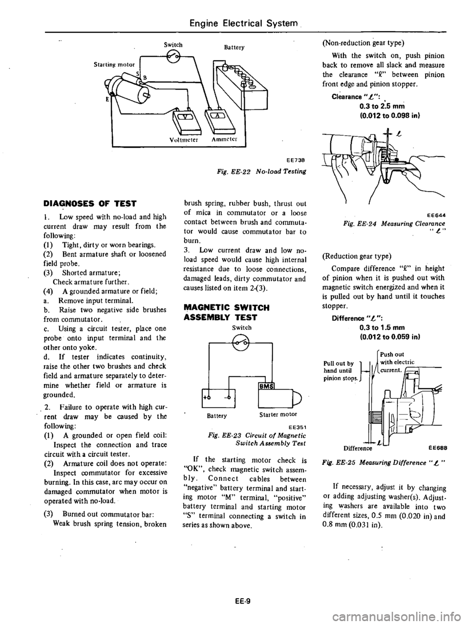
Starting
motor
S
DIAGNOSES
OF
TEST
I
Low
speed
with
no
load
and
high
current
draw
may
result
from
the
following
I
Tight
dirty
or
worn
bearings
2
Bent
armature
shaft
or
loosened
field
probe
3
Shorted
armature
Check
armature
further
4
A
grounded
armature
or
field
a
Remove
input
terminal
b
Raise
two
negative
side
brushes
from
commutator
c
Using
a
circuit
tester
place
one
probe
onto
input
terminal
and
the
other
onto
yoke
d
If
tester
indicates
continuity
raise
the
other
two
brushes
and
check
field
and
armature
separately
to
deter
mine
whether
field
or
armature
is
grounded
2
Failure
to
operate
with
high
cur
rent
draw
may
be
caused
by
the
following
I
A
grounded
or
open
field
coil
Inspect
the
connection
and
trace
circuit
with
a
circuit
tester
2
Armature
coil
does
not
operate
Inspect
commutator
for
excessive
burning
In
this
case
arc
may
occur
on
damaged
commutator
when
motor
is
operated
with
no
load
3
Burned
out
commutator
bar
Weak
brush
spring
tension
broken
Engine
Electrical
System
Switch
Battery
Vultmeter
Ammeter
EE738
Fig
EE
22
No
load
Testing
brush
spring
rubber
bush
thrust
out
of
mica
in
commuta
tor
or
a
loose
contact
between
brush
and
conunuta
tor
would
cause
commutator
bar
to
burn
3
Low
current
draw
and
low
no
load
speed
would
cause
high
internal
resistance
due
to
loose
connections
damaged
leads
dirty
commutator
and
causes
listed
on
item
2
3
MAGNETIC
SWITCH
ASSEMBLY
TEST
Switch
2
1
6
11
p
IB
b
I
Battery
Starter
motor
EE351
Fig
EE
23
Circuit
of
Magnetic
Switch
Assembly
Test
If
the
starting
motor
check
is
OK
check
magnetic
switch
assem
bly
Connect
cables
between
negative
battery
terminal
and
start
ing
motor
M
terminal
positive
battery
terminal
and
starting
motor
8
terminal
connecting
a
switch
in
series
as
shown
above
EE
9
Non
reduction
gear
type
With
the
switch
on
push
pinion
back
to
remove
all
slack
and
measure
the
clearance
between
pinion
front
edge
and
pinion
stopper
Clearance
L
0
3
to
2
5
mm
0
012
to
0
098
in
EE644
Fig
EE
24
Measuring
Clearance
l
Reduction
gear
type
Compare
difference
2
in
height
of
pinion
when
it
is
pushed
out
with
magnetic
switch
energized
and
when
it
is
pulled
out
by
hand
until
it
touches
stopper
Difference
L
0
3
to
1
5
mm
0
012
to
0
059
in
Pull
out
by
hand
until
pinion
stops
Push
out
1
1
n
11
r
L
Difference
EE688
Fig
EE
25
Measuri
g
Difference
L
If
necessary
adjust
it
by
changing
or
adding
adjusting
washer
s
Adjust
ing
washers
are
available
into
two
different
sizes
0
5
mm
0
020
in
and
0
8
mm
0
031
in
Page 190 of 548

Engine
Electrical
System
STARTING
MOTOR
Type
S1I4
160B
I
Sl14
163E
S114
253
Outer
diameter
of
commutator
mm
in
More
than
32
1
26
More
than
29
L14
Minimum
length
of
brush
mm
in
12
0
47
II
0
43
Brush
spring
tension
kg
Ib
1
4
to
1
8
3
1
to
4
0
1
6to
2
0
3
5
to
4
4
Clearance
between
bearing
metal
and
armature
shaft
mm
in
Less
than
0
2
0
008
Clearance
R
between
pinion
front
edge
and
pinioIl
stopper
mm
in
0
3
to
2
5
0
012
to
0
098
Difference
T
in
height
of
pinion
nun
in
0
3
to
1
5
0
012
to
0
059
ALTERNATOR
Type
LRI5049
Minimum
length
of
brush
mm
in
More
than
7
5
0
295
Brush
spring
pressure
gr
oz
255
to
345
8
99
to
12
17
Slip
ring
outer
diameter
nun
in
More
than
30
1
18
DISTRIBUTOR
Air
gap
mm
in
D4K8
19
I
D4K8
l3
I
D4K8
18
I
D4K8
02
D4K8
15
I
D4K8
16
0
3
to
0
5
0
012
to
0
020
Type
Cap
il1s
ation
resistance
M
1
More
than
50
Rotor
head
insulation
resistance
Mil
More
than
50
Cap
carbon
point
length
mm
in
10
0
39
Vacuum
advance
0
105
4
13
0
170
6
69
0
80
3
15
0
105
4
13
0
70
2
76
0
170
6
69
Distributor
degree
distributor
9
250
3
225
12
265
9
300
15
300
6
5
300
mmHg
inHg
9
84
8
86
10
43
11
81
11
81
11
81
Centrifugal
advance
0
550
6
550
0
550
0
550
0
750
0
750
Distributor
degree
distributor
14
2
300
14
2
300
13
5
2
400
13
5
2
400
10
2
400
10
2
400
rpm
EE
32
Page 203 of 548
DATSUN
210
Model
8310
Series
SECTIONCL
CLUTCH
CONTENTS
ADJUSTMENT
CLUTCH
PEDAL
HEIGHT
CLUTCH
PEDAL
FREE
TRAVEL
BLEEDING
CLUTCH
SYSTEM
CLUTCH
CONTROL
CLUTCH
PEDAL
CLUTCH
MASTER
CYLINDER
OPERATING
CYLINDER
CLUTCH
LINE
CLUTCH
UNIT
CLUTCH
DISC
AND
COVER
CL
2
CL
2
CL
2
CL
2
CL
3
CL
3
CL
4
CL
5
CL
6
CL
7
CL
7
RELEASE
BEARING
PILOT
BUSHING
SERVICE
DATA
AND
SPECIFICATIONS
GENERAL
SPECIFICATIONS
INSPEctiON
AND
ADJUSTMENT
TIGHTENING
TORQUE
TROUBLE
DIAGNOSES
AND
I
ECTIONS
SPECIAL
SERVICE
TOOLS
CL
8
CL
9
CL
10
CL
10
CL10
CL
11
CL
12
CL
14
Page 204 of 548
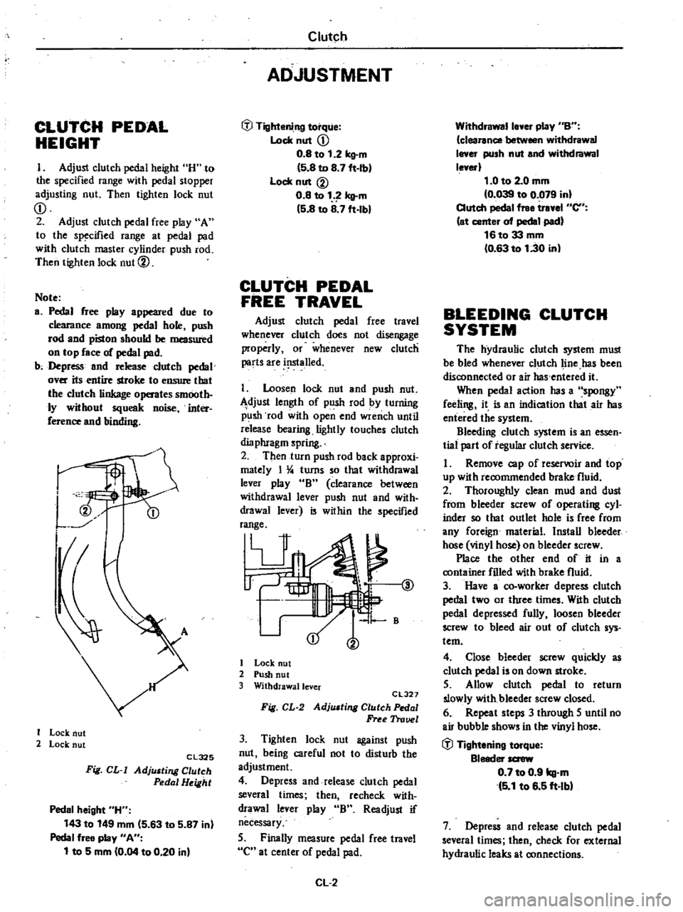
CLUTCH
PEDAL
HEIGHT
I
Adjust
clutch
pedal
height
H
to
the
specified
range
with
pedal
stopper
adjusting
nut
Then
tighten
lock
nut
CD
2
Adjust
clutch
pedal
free
play
A
to
the
specified
range
at
pedal
pad
with
clutch
master
cylinder
push
rod
Then
tighten
lock
nut
@
Note
a
Pedal
free
play
appeared
due
to
clearance
among
pedal
hole
push
rod
and
piston
should
be
measured
on
top
face
of
pedal
pad
b
Depress
and
release
clutch
pedal
over
its
entire
stroke
to
ensure
that
the
clutch
linkage
operates
smooth
ly
without
squeak
noise
inter
ference
and
binding
I
I
Lock
nut
2
Lock
nut
Cl325
Fig
CL
I
AdjlUting
Clutch
Pedal
Height
Pedal
height
H
143
to
149
mm
5
63
to
5
87
in
Pedal
free
play
An
1
to
5
mm
0
04
to
0
20
in
Clutch
ADJUSTMENT
tfl
Tightening
torque
Lock
nut
CD
0
8
to
1
2
kg
m
5
8
to
8
7
ft
Ib
Lock
nut
@
0
8
to
1
Icll
m
5
8
to
8
7
ft
lbl
CLUTCH
PEDAL
FREE
TRAVEL
Adjust
clutch
pedal
free
travel
whenever
clutch
does
not
disengage
properly
or
whenever
new
clutch
parts
are
i
lslalled
I
Loosen
lock
nut
and
push
nut
djust
length
of
push
rod
by
turning
p
lsh
rod
with
open
end
wrench
until
release
bearing
lightly
touches
clutch
dia
phragm
spring
2
Then
turn
push
rod
back
approxi
mately
I
4
turns
so
that
withdrawal
lever
play
B
clearance
between
withdrawal
lever
push
nut
and
with
drawal
lever
is
within
the
specified
range
V
@
1
B
I
Lock
nut
2
Push
nut
3
Withdrawallcver
CL327
Fig
CL
2
AdjlUting
Clutch
Pedal
Free
Trauel
3
Tighten
lock
nut
against
push
nut
being
careful
not
to
disturb
the
adjustment
4
Depress
and
release
clutch
pedal
several
times
then
recheck
with
drawal
lever
play
B
Readjust
if
necessary
5
Finally
measure
pedal
free
travel
C
at
center
of
pedal
pad
CL
2
Withdrawalle
er
play
nBn
clearance
between
withdrawal
I
er
push
nut
and
withdrawal
le
erl
1
0
to
2
0
mm
0
039
to
0
079
in
Clutch
pedal
free
tr
el
en
at
center
of
pedal
pad
16to33
mm
0
63
to
1
30
in
BLEEDING
CLUTCH
SYSTEM
The
hydraulic
clutch
system
must
be
bled
whenever
clutch
line
has
been
disconnected
or
air
has
entered
it
When
pedal
action
has
a
spongy
feeling
it
is
an
indication
that
air
has
entered
the
system
Bleeding
clutch
system
is
an
essen
tial
part
of
regular
clutch
service
I
Remove
cap
of
reservoir
and
top
up
with
recommended
brake
fluid
2
Thoroughly
clean
mud
and
dust
from
bleeder
screw
of
operating
cyl
inder
so
that
outlet
hole
is
free
from
any
foreign
material
Install
bleeder
hose
vinyl
hose
on
bleeder
screw
Place
the
other
end
of
it
in
a
container
filled
with
brake
fluid
3
Have
a
co
worker
depress
clutch
pedal
two
or
three
times
With
clutch
pedal
depressed
fully
loosen
bleeder
screw
to
bleed
air
out
of
clutch
sys
tem
4
Close
bleeder
screw
quickly
as
clutch
pedal
is
on
down
stroke
5
Allow
clutch
pedal
to
return
slowly
with
bleeder
screw
closed
6
Repeat
steps
3
through
5
until
no
air
bubble
shows
in
the
vinyl
hose
tfl
Tightening
torque
Bleeder
screw
0
7
to
0
9
kg
m
5
1
to
6
5
ft
lbl
7
Depress
and
release
clutch
pedal
several
times
then
check
for
external
hydraulic
leaks
at
connections