glove box DATSUN 210 1979 Service Manual
[x] Cancel search | Manufacturer: DATSUN, Model Year: 1979, Model line: 210, Model: DATSUN 210 1979Pages: 548, PDF Size: 28.66 MB
Page 441 of 548

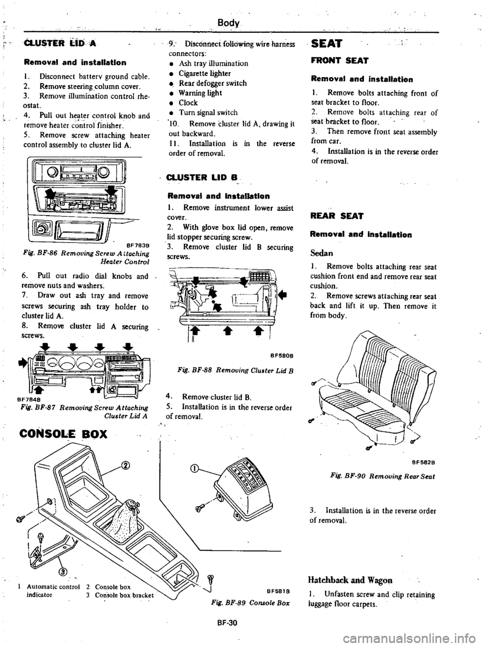
CLUSTER
I
IDA
Removal
and
installation
I
Disconnect
batterv
ground
cable
2
Remove
steering
column
cover
3
Remove
illumination
control
rhe
ostat
4
Pull
out
heater
control
knob
and
remove
heater
c
ntrol
finisher
5
Remove
screw
attaching
heater
control
assembly
to
cluster
lid
A
nQ
lQ
Ii
tl
rffmfLu
O
r
BF783B
Fig
BF
86
Removing
Screw
A
Uoching
Heater
Control
6
Pull
out
radio
dial
knobs
and
remove
nuts
and
washers
7
Draw
out
ash
tray
and
remove
screws
securing
ash
tray
holder
to
cluster
lid
A
B
Remove
cluster
lid
A
securing
screws
1
G808
iS
Ill
1
CJy
BF7848
Fig
BF
87
Remooing
Screw
Attaching
Cluster
Lid
A
CONSOLE
BOX
@
01
Automatic
control
2
Console
box
indicator
3
Console
box
bracket
Body
9
Disconnect
following
wire
harness
connectors
Ash
tray
illumination
Cigarette
lighter
Rear
defogger
switch
Warning
light
Clock
Turn
signal
switch
10
Remove
cluster
lid
A
drawing
it
out
backward
11
Installation
is
in
the
reverse
order
of
removal
CLUSTER
LID
B
Removal
and
Installation
I
Remove
instrument
lower
assist
cover
2
With
glove
box
lid
open
remove
lid
stopper
securing
screw
3
Remove
cluster
lid
B
securing
screws
i
i
ll
r
II
I
BF580B
Fig
BF
88
Removing
Cluster
Lid
B
4
Remove
cluster
lid
B
5
Installation
is
in
the
reverse
order
of
removal
J
BF581
B
Fig
BF
89
Console
Bo
SF
30
SEAT
FRONT
SEAT
Removal
and
installation
I
Remove
bolts
attaching
front
of
seat
bracket
to
floor
2
Remove
bolts
attaching
rear
of
seat
bracket
to
floor
3
Then
remove
front
seat
assembly
from
car
4
Installation
is
in
the
reverse
order
of
removal
REAR
SEAT
Removal
and
Installation
Sedan
I
Remove
bolts
attaching
rear
seat
cushion
front
end
and
remove
rear
seat
cushion
2
Remove
screws
attaching
rear
seat
back
and
lift
it
up
Then
remove
it
from
body
f
I
8F5828
Fig
BF
90
Removing
Rear
Seat
3
Installation
is
in
the
reverse
order
of
removaL
Hatchback
and
Wagon
I
Unfasten
screw
and
clip
retaining
luggage
floor
carpets
Page 522 of 548

REFRIGERANT
LINES
Air
Conditioning
@
I
J
L
S
r
Z
S
t
@
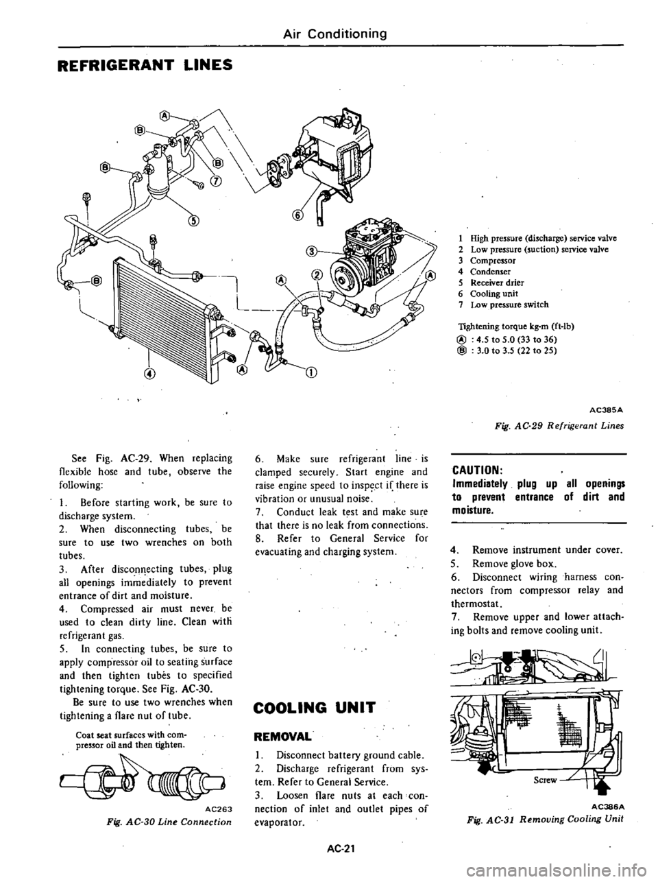
See
Fig
AC
29
When
replacing
flexible
hose
and
tube
observe
the
following
1
Before
starting
work
be
sure
to
discharge
system
2
When
disconnecting
tubes
be
sure
to
use
two
wrenches
on
both
tubes
3
After
discon
ecting
tubes
plug
all
openings
immediately
to
prevent
entrance
of
dirt
and
moisture
4
Compressed
air
must
never
be
used
to
clean
dirty
line
Clean
with
refrigerant
gas
5
In
connecting
tubes
be
sure
to
apply
compressor
oil
to
seating
surface
and
then
tighten
tubes
to
specified
tightening
torque
See
Fig
AC
30
Be
sure
to
use
two
wrenches
when
tightening
a
flare
nut
of
tube
Coat
seat
surfaces
with
com
pressor
oil
and
then
tighten
AC263
Fig
AC
30
Line
Connection
CD
6
Make
sure
refrigerant
line
is
clamped
securely
Start
engine
and
raise
engine
speed
to
inspect
if
there
is
vibration
or
unusual
noise
7
Conduct
leak
t
st
and
make
su
e
that
there
is
no
leak
from
connections
8
Refer
to
General
Service
for
evacuating
and
charging
system
COOLING
UNIT
REMOVAL
I
Disconnect
battery
ground
cable
2
Discharge
refrigerant
from
sys
tern
Refer
to
General
Service
3
Loosen
flare
nuts
at
each
con
nection
of
inlet
and
outlet
pipes
of
evaporator
AC
21
1
High
pressure
discharge
service
valve
2
Low
pressure
suction
service
valve
3
Compressor
4
Condenser
5
Receiver
drier
6
Cooling
unit
7
Low
pressure
switch
lightening
torque
kg
m
ft
lb
@
4
5
to
5
0
33
to
36
@
3
0
to
3
5
22
to
25
AC385A
Fig
AC
29
Refrigerant
Lines
CAUTION
Immediatelv
plug
up
all
openings
to
prevent
entrance
of
dirt
and
moisture
4
Remove
instrument
under
cover
5
Remove
glove
box
6
Disconnect
wiring
harness
con
nectors
from
compressor
relay
and
thermostat
7
Remove
upper
and
lower
attach
ing
bolts
and
remove
cooling
unit
AC386A
Fig
AC
31
Removing
Cooling
Unit
Page 524 of 548

Note
When
installing
thermostat
in
sert
capillary
tube
in
same
place
as
it
was
before
removal
Be
sure
to
insert
capillary
tube
end
about
SO
em
19
7
in
from
evaporator
core
INSPECTION
1
Test
continuity
between
two
switch
terminals
with
test
lamp
or
ohmmerter
Continuity
should
exist
2
With
capillary
tube
end
dipped
into
ice
salt
water
maintained
to
I
oc
300
F
test
continuity
between
two
switch
terminals
Continuity
should
not
exist
3
If
switch
is
found
damaged
re
place
MAIN
RELAY
REMOVAL
AND
INSTALLATION
I
Disconnect
battery
ground
cable
2
Remove
glove
box
3
Disconnect
connector
from
main
relay
4
Remove
screw
retaining
main
relay
to
cooling
unit
then
remove
main
relay
5
Installation
is
in
the
reverse
order
of
removal
INSPECTION
Test
continuity
of
relay
with
ohm
meter
or
test
lamp
In
testing
main
relay
there
must
be
continuity
be
tween
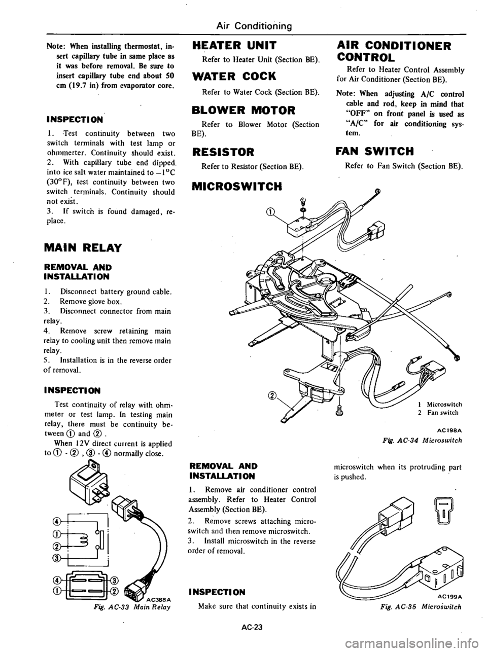
CD
and
CV
When
l2Y
direct
current
is
applied
to
CD
CV
CID
@
normally
close
ti
I
I
6
i
i
f
i
f
Fig
AC
33
Air
Conditioning
HEATER
UNIT
Refer
to
Heater
Unit
Section
BE
WATER
COCK
Refer
to
Water
Cock
Section
BE
BLOWER
MOTOR
Refer
to
Blower
Motor
Section
BE
RESISTOR
Refer
to
Resistor
Section
BE
MICROSWITCH
CV
REMOVAL
AND
INSTALLATION
1
Remove
air
conditioner
control
assembly
Refer
to
Heater
Control
Assembly
Section
BE
2
Remove
screws
attaching
micro
switch
and
then
remove
rnicroswitch
3
Install
rnicroswitch
in
the
reverse
order
of
removal
I
NSPECTI
ON
Make
sure
that
continuity
exists
in
AC
23
AIR
CONDITIONER
CONTROL
Refer
to
Heater
Control
Assembly
for
Air
Conditioner
Section
BE
Note
When
adjusting
AIC
control
cable
and
rod
keep
in
mind
that
OFF
on
front
panel
is
used
as
A
C
for
air
conditioning
sys
tem
FAN
SWITCH
Refer
to
Fan
Switch
Section
BE
1
Microswitch
2
Fan
switch
AC19SA
Fig
AC
34
Microswitch
rnicroswitch
when
its
protruding
part
is
pushed
w
AC199A
Fig
AC
35
Microswitch
Page 525 of 548

LOW
PRESSURE
SWITCH
REMOVAL
AND
INSTALLATION
I
Disconnect
battery
ground
cable
2
Discharge
refrigerant
from
sys
tem
Refer
to
General
Service
3
Disconnect
connector
to
low
pressure
switch
4
Remove
low
pressure
switch
by
turning
the
switch
5
Installation
is
in
the
reverse
order
of
removal
INSPECTION
Using
a
circuit
tester
make
sure
that
low
pressure
switch
exhibits
con
tinuity
when
gas
pressure
of
refriger
ant
in
system
is
normal
and
that
low
pressure
switch
does
not
exhibit
con
tinuity
when
gas
pressure
drops
below
2
2
kg
cm2
31
p
i
MAGNET
VALVE
REMOVAL
AND
INSTALLATION
I
Disconnect
battery
ground
cable
2
Disconnect
magnet
valve
lead
wires
and
vacuum
hoses
3
Remove
magnet
valve
securing
screws
and
then
remove
magnet
valve
i
i
WrE
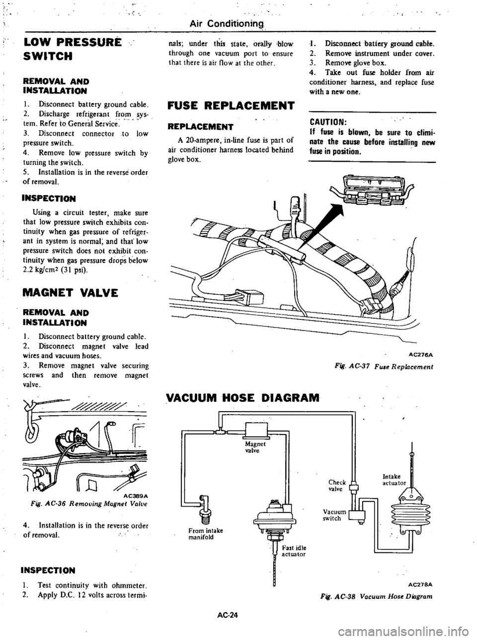
AC389A
Fig
AC
36
Removjng
Magnet
Valve
4
Installation
is
in
the
reverse
order
of
removal
INSPECTION
I
rest
continuity
with
ohmmeter
2
Apply
D
C
12
volts
across
termi
Air
Conditioning
031
under
this
state
orally
blow
through
one
vacuum
port
to
ensure
that
there
is
air
flow
at
the
other
FUSE
REPLACEMENT
REPLACEMENT
A
20
ampere
in
line
fuse
is
part
of
air
conditioner
harness
located
behind
glove
box
J
Disconnect
batiery
ground
cable
2
Remove
instrument
under
cover
3
Remove
glove
box
4
Take
out
fuse
holder
from
air
conditioner
harness
and
replace
fuse
with
a
new
one
CAUTION
If
fuse
is
blown
be
sure
to
climi
nate
the
cause
befure
installing
new
fuse
in
position
r
AC276A
Fig
AC
37
Fu
e
Replacement
VACUUM
HOSE
DIAGRAM
u
CJ
Magnet
valve
Al
1
From
intake
manifold
AC
24
Fast
idle
actuator
Check
valve
Vacuum
switch
Intake
actuator
I
0
0
2
S
1l
AC27BA
Fig
AC
38
Vacuum
Hose
Diagram