key DATSUN 210 1979 Service Manual
[x] Cancel search | Manufacturer: DATSUN, Model Year: 1979, Model line: 210, Model: DATSUN 210 1979Pages: 548, PDF Size: 28.66 MB
Page 14 of 548
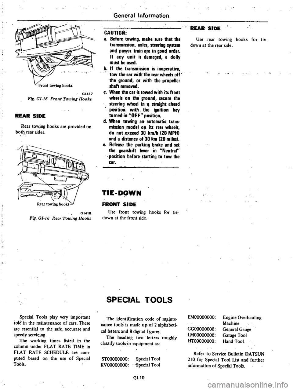
GI417
Fig
GI
15
Front
Towing
Hook
REAR
SIDE
Rear
towing
hooks
are
provided
on
bot
rear
sides
GI418
Fig
GI
16
Rear
Towing
Hooks
Special
Tools
play
very
important
role
in
the
maintenance
of
cars
These
are
essential
to
the
safe
accurate
and
speedy
servicing
The
working
times
listed
in
the
column
under
FLAT
RATE
TIME
in
FLAT
RATE
SCHEDULE
are
com
puted
based
on
the
use
of
Special
Tools
General
Information
CAUTION
a
Before
towing
make
sure
that
the
transmission
axles
steering
system
and
p
r
train
are
in
good
order
If
any
unit
is
damaged
a
dolly
must
be
used
If
the
transmission
is
inoperative
tow
the
car
with
the
rear
wheels
off
the
ground
or
with
the
propeller
shaft
removed
c
When
the
car
is
towed
with
its
front
wheels
on
the
ground
secure
the
steering
wheel
in
a
straight
ahead
position
with
the
ignition
key
turnedin
OFF
position
d
When
towing
an
automatic
trans
mission
model
on
its
rear
wheels
do
not
exceed
30
km
h
20
MPH
and
a
distance
of30
km
20
miles
e
Release
the
parking
brake
and
set
the
gearshift
lever
in
Neutral
position
before
starting
to
tow
the
car
TIE
DOWN
FRONT
51
DE
Use
front
towing
hooks
for
tie
down
at
the
front
side
SPECIAL
TOOLS
The
identification
code
of
ffi
linte
nance
tools
is
made
up
of
2
alphabeti
calletters
and
8
digital
figures
The
heading
two
letters
roughly
classify
tools
c
equipment
as
STOOOOOOOO
KVOOOOOOOO
Special
Tool
Special
Tool
GI
l0
REAR
SIDE
Use
rear
towing
hooks
for
tie
down
at
the
rear
side
EMOOOOOOOO
GGOOOOOOOO
lMOOOOOOOO
HTOOOOOOOO
Engine
Overhauling
Machine
General
Gauge
Garage
Tool
Hand
Tool
Refer
to
Service
Bulletin
DATSUN
210
fOJ
Special
Tool
List
and
further
information
of
Special
Tools
Page 51 of 548
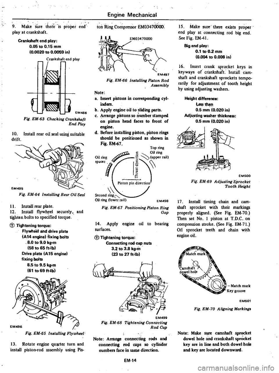
9
Make
SUre
there
is
proper
end
play
at
crankshaft
Crankshaft
end
play
0
05toO
15mm
0
OO20
to
0
0059
in
laJlk
h
end
play
J
EM486
Fig
EM
63
Checking
Crank
luJft
End
Play
10
Install
rear
oil
seal
using
suitable
drift
Fig
EM
64
n
talling
Rear
Oil
Seal
II
Install
rear
plate
12
Install
flywh
el
secwely
and
tighten
bolts
to
specified
torque
dl
Tightening
torque
Flywheel
and
drive
plate
A
14
engine
fixing
bolts
8
0
to
9
0
kg
m
58
to
65
ft
Ib
Drive
plate
A
15
engine
fixing
bolts
8
5
to
9
5
kg
m
61
to
69
ft
b
Fig
EM
65
n
talling
Flywheel
13
Rotate
engine
quarter
turn
and
install
piston
rod
assembly
using
Pis
Engine
Mechanical
ton
Ring
Compressor
EM03470000
EM497
Fig
EM
66
tolling
Platon
Rod
Assem
bly
Note
a
Insert
pistons
in
L
r
nding
cyl
inders
b
Apply
engine
oil
to
sliding
parts
c
Arrange
pistons
so
number
stamped
on
piston
head
faces
to
front
of
engine
d
Before
installing
piston
piston
rings
should
be
positioned
as
shown
in
Fig
EM
67
Second
ring
Oil
ring
lower
rail
EM49B
Fig
EM
67
Positioning
Piston
Ring
Gap
14
Apply
engine
oil
to
bearing
surfaces
dl
Tighte
ning
torque
Connecting
rod
cap
nuts
3
2
to
3
8
kg
m
23
to
27
ft
b
EM499
Fig
EM
68
Tightening
Connecting
Rod
Cap
Note
Am11
connecting
rods
and
connecting
rod
caps
so
cylinder
numben
face
in
same
direction
EM
14
I
S
Make
sure
there
exists
proper
end
play
at
connecting
rod
big
end
See
Fig
EM41
Big
end
play
0
1
to
0
2
mm
0
004
to
0
008
in
16
Insert
crank
sprocket
keys
in
keyways
of
crankshaft
Install
cam
shaft
and
crankshaft
sprockets
tempo
rarily
for
adjustment
of
tooth
height
by
using
adjusting
washers
Height
dif
Less1
h
l11
0
5
mm
0
020
in
Adjusting
washer
thickness
0
5
mm
10
020
in
EM500
Fig
EM
69
Adju
ting
Sprocket
Tooth
Height
17
Install
tinting
chain
and
cam
shaft
sprocket
with
their
markings
properly
aligned
See
Fig
EM
70
Then
set
No
I
piston
at
T
D
C
on
compression
stroke
See
Fig
EM
71
Oil
sprocket
teeth
and
chain
with
engine
oil
Match
mark
Key
groove
EM501
Fig
EM
70
Aligning
Markinga
Note
Make
sure
camshaft
sprocket
dowel
hole
and
crankshaft
sprocket
key
are
in
line
and
both
dowel
hole
and
key
are
located
downward
Page 52 of 548
m
k
camSM9tJ
down
hole
Key
groove
EM767
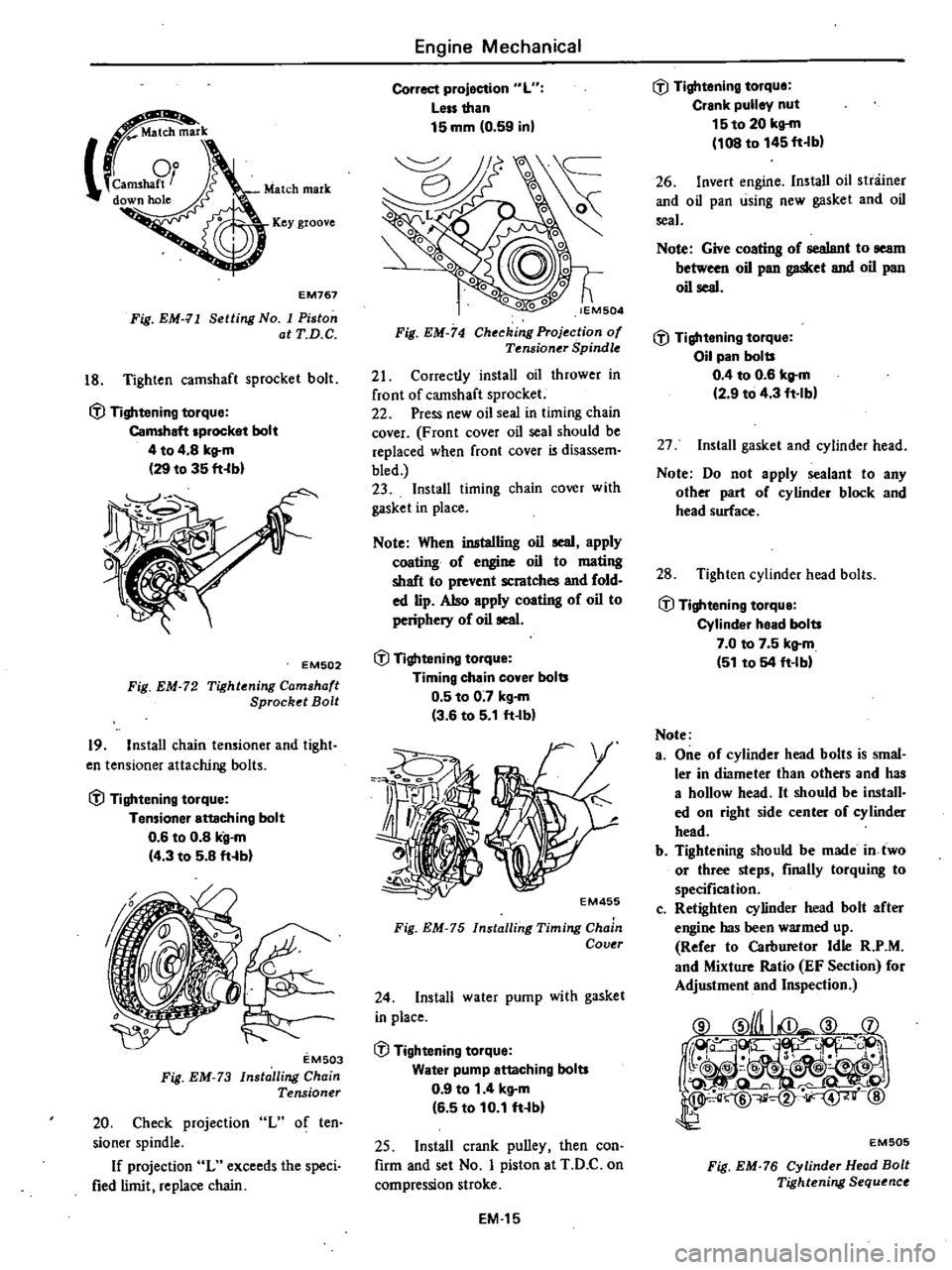
Fig
EM
11
Setting
No
I
Piston
atT
D
C
18
Tighten
camshaft
sprocket
bolt
ifl
Tightening
torque
Camshaft
sprocket
bolt
4
to
4
8
kg
m
29
to
35
fHbl
EM502
Fig
EM
72
Tightening
Camshaft
Sprocket
Bolt
19
Install
chain
tensioner
and
tight
en
tensioner
attaching
bolts
ifl
Tightening
torque
Tensioner
enaching
bolt
0
6
to
0
8
kg
m
14
3
to
5
8
ft
b
EM503
Fig
EM
73
Installing
Chain
Tensioner
20
Check
projection
L
of
ten
sioner
spindle
If
projection
L
exceeds
the
speci
fied
limit
replace
chain
Engine
Mechanical
Correct
projection
L
Less
than
15
mm
0
59
inl
lEM504
Fig
EM
74
Checking
Projection
of
Tf
nsioner
Spindle
21
Correctly
install
oil
thrower
in
front
of
camshaft
sprocket
22
Press
new
oil
seal
in
timing
chain
cover
F
ran
t
cover
oil
seal
should
be
replaced
when
front
cover
is
disassem
bled
23
Install
timing
chain
cover
with
gasket
in
place
Note
When
inatalling
oil
seal
apply
coating
of
engine
oil
to
mating
shaft
to
prevent
scratches
and
fold
ed
lip
Also
apply
coating
of
oil
to
periphery
of
oil
seal
ifl
Tightening
torque
Timing
chain
cover
bolts
0
5
to
0
7
kg
m
3
6
to
5
1
ft
Ib
Z5
1
o
j
I
t
f
4
EM455
Fig
EM
75
Installing
Timing
Chain
Covtr
24
Install
water
pump
with
gasket
in
place
ifl
Tightening
torque
Water
pump
attaching
bolts
0
9
to
1
4
kg
m
16
5
to
10
1
ft
bl
25
Install
crank
pulley
then
con
firm
and
set
No
I
piston
at
T
D
C
on
compression
stroke
EM
15
ifl
Tightening
torque
Crank
pulley
nut
15to
20
kg
m
108
to
145
ft
b
26
Invert
engine
Install
oil
stniiner
and
oil
pan
using
new
gasket
and
oil
seal
Note
Give
coating
of
sealant
to
seam
between
oil
pan
gasket
and
oil
pan
oil
seal
ifl
Tightening
torque
Oil
pan
bolts
0
4
to
0
6
kg
m
12
9
to
4
3
ft
lb
27
Install
gasket
and
cylinder
head
Note
Do
not
apply
sealant
to
any
other
part
of
cylinder
block
and
head
surface
28
Tighten
cylinder
head
bolts
ifl
Tightening
torque
Cylinder
head
bolts
7
0
to
7
5
kg
m
51
to
54
ft
IM
Note
a
One
of
cylinder
head
bolts
is
smal
ler
in
diameter
than
others
and
has
a
hollow
head
It
should
be
install
ed
on
right
side
center
of
cylinder
head
b
Tightening
should
be
made
in
two
or
three
steps
finally
torquing
to
specification
c
Retighten
cylinder
head
bolt
after
engine
has
been
warmed
up
Refer
to
Carburetor
Idle
R
P
M
and
Mixture
Ratio
EF
Section
for
Adjustment
and
Inspection
EM505
Fig
EM
76
Cylinder
Head
Bolt
Tightening
Sequence
Page 93 of 548
DESCRIPTION
The
carburetors
are
of
downdraft
two
barrel
type
designed
to
increase
ppwe
r
a
fu
l
eC
l
Il
Y
t
3
ell
a
to
reduce
exhaust
gas
emissions
These
carburetors
present
several
distinct
features
of
importance
to
car
owner
A
summary
of
features
is
as
fol
lows
1
Secondary
throttle
valve
is
oper
ated
by
throttle
lever
High
power
and
good
acceleration
are
gained
with
com
bination
of
the
auxiliary
valve
2
Accelerating
pump
provide
ex
cellent
acceleration
3
Power
valve
mechanism
is
a
vacuo
urn
actuated
boost
type
and
improves
high
speed
driving
4
The
throttle
opener
control
sys
tem
Except
FU
model
incorporates
a
servo
diaphragm
which
helps
open
the
throttle
valve
at
a
decreasing
speed
so
as
to
reduce
hydrocarbon
emissions
to
a
minimum
5
An
anti
d
eseling
solenoid
valve
is
installed
to
prevent
dieseling
When
ignition
key
is
turned
off
the
fuel
passage
involved
in
the
ow
system
is
closed
and
the
fuel
supply
is
shut
down
completely
The
solenoid
valve
also
serves
as
an
actuator
of
the
fuel
shut
off
system
on
the
FU
model
6
In
the
choke
mechanism
an
elec
trie
automatic
choke
is
used
to
auto
maticaDy
control
chok
valve
opera
tion
during
engin
war
up
7
The
carburetor
comes
equipped
with
dash
pot
which
ensures
smooth
deceleration
without
engine
stall
under
aU
operating
conditions
STRUCTURE
AND
OPERATION
These
carburetors
consist
of
a
main
system
for
normal
running
a
slow
system
for
idling
and
an
accelerating
and
power
mechanisIll
Some
emission
control
devices
are
added
E
ngine
Fuel
CARBURETOR
I
J
1
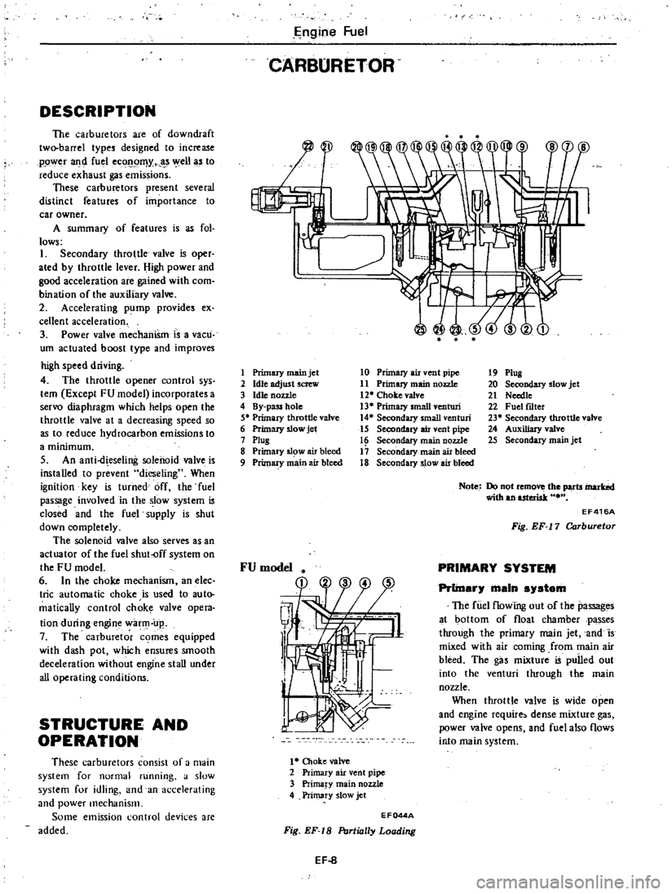
Primary
main
jet
2
Idle
adjust
screw
3
hUe
nozzle
4
By
pass
hole
5
Primary
throttle
valve
6
Primary
slow
jet
7
ptug
8
Primary
5l
w
air
bleed
9
Primary
main
air
bleed
10
Primary
air
vent
pipe
11
Primuy
main
nozzle
12
Choke
valve
13
Primary
small
venturi
14
Secondary
small
venturi
15
Secondary
air
vent
pipe
16
Secondary
main
nozzle
17
Secondary
main
air
bleed
18
Secondary
slow
air
bleed
1
Oloke
valve
2
Primary
air
vent
pipe
3
Prima
y
main
nozzle
4
Primary
slow
jet
19
Plug
20
Secondary
slow
jet
21
Needte
22
Fuel
fLlter
23
Secondary
tIuottle
valve
24
Auxiliary
valve
25
Secondary
main
jet
Note
Do
not
remo
the
parts
inarbd
with
anuteriak
EF416A
Fig
EF
17
Carburetor
PRIMARY
SYSTEM
PrlinarJ
main
sJstam
The
fUel
flowing
out
of
the
passages
at
bottom
of
float
chamber
passes
through
the
primary
main
jet
and
is
mixed
with
air
coming
from
main
air
bleed
The
gas
mixture
is
pulled
out
into
the
venturi
through
the
main
nozzle
When
throttle
valve
is
wide
open
and
engine
require
dense
mixture
gas
power
valve
opens
and
fuel
also
flows
into
main
system
EF044A
Fig
EF
18
PtJrlially
Loading
EF
8
Page 127 of 548
Emission
Control
System
EARLY
FUEL
EVAPORATIVE
E
FE
SYSTEM
DESCRIPTION
@
jl
D
W
o
0
0
UL
@
1
Intake
manifold
9
Screw
2
Stove
gasket
10
Thermostat
spring
3
Mar
fold
stove
11
Heat
control
valve
4
Heat
shield
plate
12
Control
valve
shaft
5
Snap
ring
13
Exhaust
manifold
6
Countczwcight
14
Cap
7
Key
15
Bushing
8
Stopper
pin
16
Coil
spring
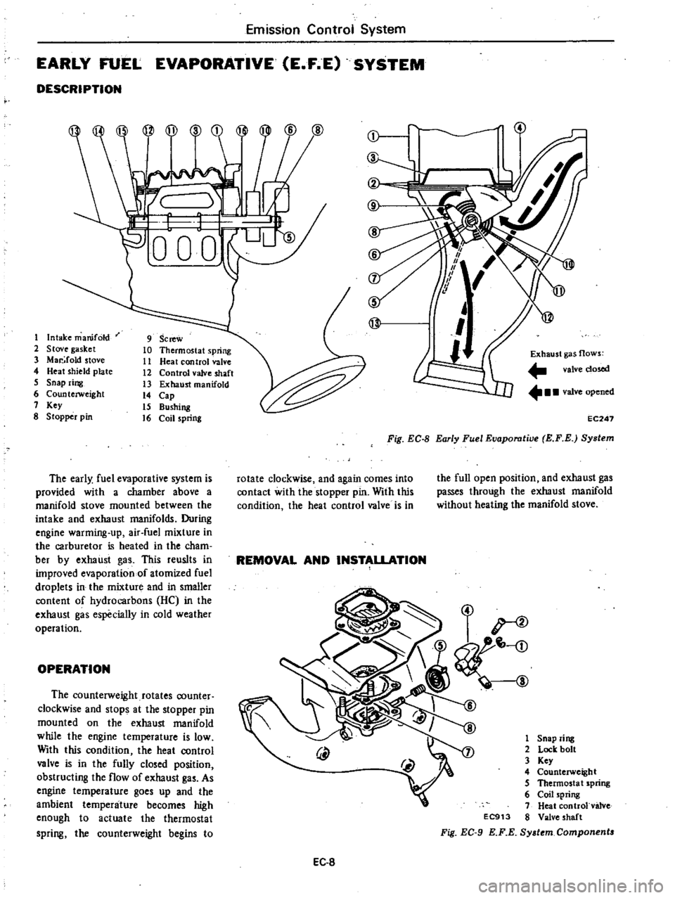
The
early
fuel
evaporative
system
is
provided
with
a
chamber
above
a
manifold
stove
mounted
between
the
intake
and
exhaust
manifolds
During
engine
warming
up
air
fuel
mixture
in
the
carburetor
is
heated
in
the
cham
ber
by
exhaust
gas
This
reuslts
in
improved
evaporation
of
atomized
fuel
droplets
in
the
mixture
and
in
smaller
content
of
hydrocarbons
HC
in
the
exhaust
gas
especially
in
cold
weather
operation
OPERATION
The
counterweight
rotates
counter
clockwise
and
stops
at
the
stopper
pin
mounted
on
the
exhaust
manifold
while
the
engine
temperature
is
low
With
this
condition
the
heat
control
valve
is
in
the
fully
closed
position
obstructing
the
flow
of
exhaust
gas
As
engine
temperature
goes
up
and
the
ambient
temperature
becomes
high
enough
to
actuate
the
thermostat
spring
the
counterweight
begins
to
j
@
l
7
1
1
5
If
@
I
Exhaust
gas
flows
valve
dosed
valve
opened
EC247
Fig
EC
8
Early
Fuel
Eaaporatiae
E
F
E
System
rotate
clockwise
and
again
comes
into
contact
with
the
stopper
pin
With
this
condition
the
heat
control
valve
is
in
the
full
open
position
and
exhaust
gas
passes
through
the
exhaust
manifold
without
heating
the
manifold
stove
REMOVAL
AND
INSTALLATION
1
Snap
ring
2
Lock
bolt
3
Key
4
Counterweight
5
Thermosta
t
spring
6
Coil
spring
7
Heat
controlvalve
EC913
8
Valve
shaft
Fig
EC
9
KF
E
Sy
tem
Component
EC
8
Page 128 of 548
Remove
snap
ring
CD
and
lock
bolt
@
and
the
following
parts
can
be
detached
from
heat
control
valve
shaft
Key
ID
Counterweight
@
Thermostat
spring
@
Coil
spring
@
Note
As
previously
descnbed
heat
control
valve
j
is
welded
to
valve
shaft
@
at
exhaust
manifold
and
cannot
be
disassembled
To
install
reverse
the
removal
procedure
INSPECTION
1
With
engine
stopped
visually
check
the
quick
heat
manifold
system
for
the
following
items
I
Check
heat
control
valve
for
malfunction
due
to
break
of
key
that
locates
counterweight
to
valve
shaft
2
Rotate
heat
control
valve
shaft
with
fingers
and
check
for
binding
between
shaft
and
bushing
in
closing
and
opening
operation
of
heat
control
valve
If
any
binding
is
felt
in
rotating
operation
move
valve
shaft
in
the
rotation
direction
several
times
If
this
operation
does
not
correct
binding
condition
it
is
due
to
seizure
between
shaft
and
bushing
and
exhaust
mani
fold
should
be
replaced
as
an
assem
bly
Emission
Control
System
Counterweight
Heat
control
valve
Stopper
pin
EC249
Fig
EC
IO
Checking
Heat
Control
Valve
Movement
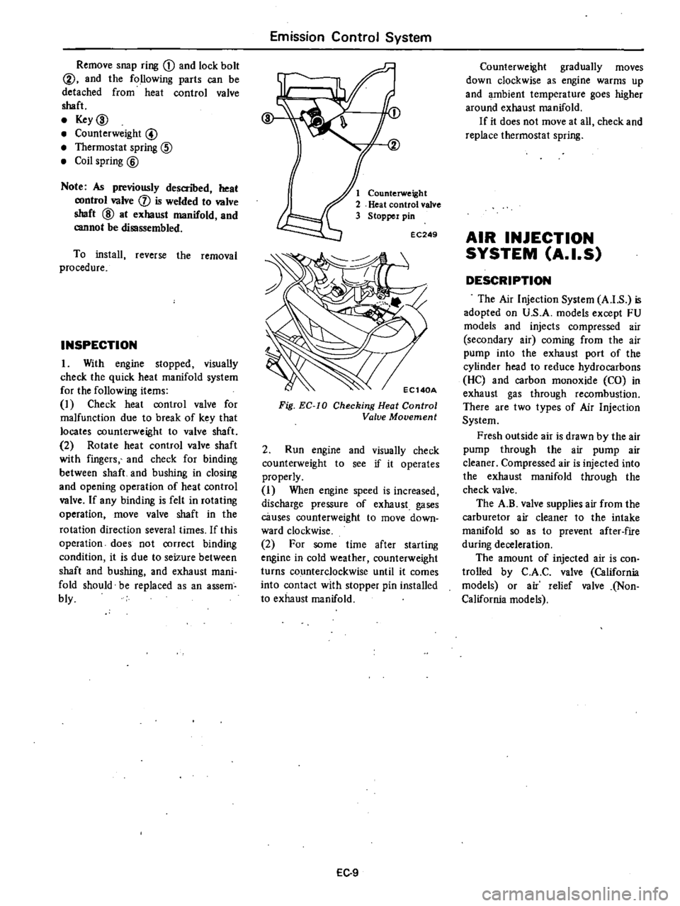
2
Run
engine
and
visually
check
counterweight
to
see
if
it
operates
properly
I
When
engine
speed
is
increased
discharge
pressure
of
exhaust
gases
causes
counterweight
to
move
down
ward
clockwise
2
For
some
time
after
starting
engine
in
cold
weather
counterweight
turns
counterclockwise
until
it
comes
into
contact
with
stopper
pin
installed
to
exhaust
manifold
EC
9
Counterweight
gradually
moves
down
clockwise
as
engine
warms
up
and
ambient
temperature
goes
higher
around
exhaust
manifold
If
it
does
not
move
at
all
check
and
replace
thermostat
spring
AIR
INJECTION
SYSTEM
A
I
S
DESCRIPTION
The
Air
Injection
System
A
I
S
is
adopted
on
U
S
A
models
except
FU
models
and
injects
compressed
air
secondary
air
coming
from
the
air
pump
into
the
exhaust
port
of
the
cylinder
head
to
reduce
hydrocarbons
He
and
carbon
monoxide
CO
in
exhaust
gas
through
recombustion
There
are
two
types
of
Air
Injection
System
Fresh
outside
air
is
drawn
by
the
air
pump
through
the
air
pump
air
cleaner
Compressed
air
is
injected
into
the
exhaust
manifold
through
the
check
valve
The
A
B
valve
supplies
air
from
the
carburetor
air
cleaner
to
the
intake
manifold
so
as
to
prevent
after
fire
during
deceleration
The
amount
of
injected
air
is
con
trolled
by
C
A
C
valve
California
models
or
air
relief
valve
Non
California
models
Page 301 of 548

Automatic
Transmission
TROUBLE
SHOOTING
GUIDE
FOR
3N71B
AUTOMATIC
TRANSMISSION
Ordel
Test
item
Checking
Oil
level
gauge
j
Downshift
solenoid
3
Manual
linkage
4
Inhibitor
switch
5
Engine
idling
rpm
6
Vacuum
pressure
of
vacuum
pipe
7
Operation
in
each
range
g
Creep
of
vehicle
Stall
test
1
Oil
pressure
before
t
sting
2
Stall
test
3
Oil
pressure
after
teSling
Road
test
L
Slow
acceleration
Ist
2nd
2nd
3rd
2
Quick
acceleration
Ist
2nd
2nd
3rd
3
Kick
down
operation
3rd
2nd
or
2nd
1st
Procedure
Check
gauge
for
oil
level
and
leakage
before
and
after
each
test
Check
for
sound
of
operating
solenoid
when
depressing
accelerator
pedal
fully
with
ignition
key
ON
Check
by
shifting
into
P
R
N
0
2
and
ranges
with
selector
lever
Check
whether
starter
operates
in
N
and
p
ranges
only
and
whether
reverse
lamp
operates
in
R
range
only
Check
whether
idling
rpm
meet
slandard
Check
whether
vacuum
pressure
is
more
than
450
mmHg
17
72
inHg
in
idling
and
whether
it
decreases
with
increasing
rpm
Check
whether
transmission
engages
positively
by
shifting
N
0
N
2
N
to
I
and
N
R
range
while
idling
with
brake
applied
Check
whether
there
is
any
creep
in
0
2
and
R
ranges
Measure
line
pressures
in
D
2
I
and
R
range
while
idling
Measure
engine
rpm
and
line
pressure
in
0
2
t
and
R
ranges
during
full
throttle
operation
Note
Temperature
of
torque
con
erter
oil
used
in
test
should
be
from
6
to
lOO
C
140
to
2120F
i
e
suf
ficiently
1
up
but
not
o
heeted
CAUTION
To
cool
oil
between
IIch
mil
test
for
OH
ZH
1
H
Ind
RH
nnges
idle
engine
i
e
rpm
It
Ibout
1
200
rpm
for
more
thin
1
minutll
in
P
nnge
MeeRlr
ment
time
mUlt
not
be
more
then
5
seconds
Same
as
item
1
Check
vehicle
speeds
and
engine
rpm
in
shifting
up
1
st
2nd
range
and
2nd
3rd
range
while
running
with
lever
in
D
range
and
engine
vacuum
pressure
of
about
200
mmHg
7
87
inHg
Same
as
item
1
above
except
with
engine
vacuum
pressure
of
o
mrnHg
0
inHg
i
e
in
position
just
before
kickdown
Check
whether
the
kickdown
operates
and
measure
the
time
delays
while
running
at
30
40
50
60
70
km
h
19
25
31
37
43
MPH
in
OJ
range
AT
49
Page 528 of 548
PRELIMINARY
CLEANING
Before
starting
work
remove
dirt
from
outside
the
detached
compressor
Clean
the
workbench
tool
and
your
hands
COMPRESSOR
CLUTCH
The
most
likely
source
of
problem
is
clutch
slippage
Factors
are
listed
here
Exercise
ample
care
1
Clearance
between
clutch
hub
and
pulley
should
be
0
4
to
0
6
mm
0
016
to
0
024
in
at
aU
peripheral
points
2
Make
sure
that
there
is
no
oil
or
dirt
on
friction
surfaces
of
clutch
disc
clutch
hub
and
pulley
Remove
oil
or
dirt
with
clean
lint
free
cloth
3
Make
sure
that
terminal
voltage
at
magnetic
coil
is
above
10
5V
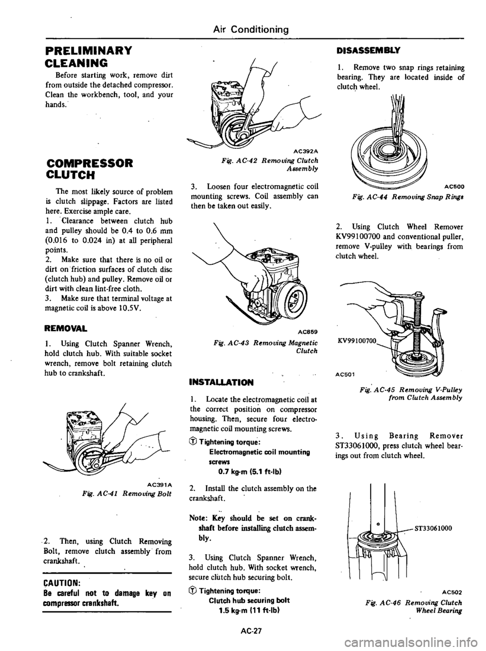
REMOVAL
I
Using
Clutch
Spanner
Wrench
hold
clutch
hub
With
suitable
socket
wrench
remove
bolt
retaining
clutch
hub
to
crankshaft
AC391A
Fig
AC
41
Removing
Bolt
2
Then
using
Clutch
Removing
Bolt
remove
clutch
assembly
from
crankshaft
CAUTION
Be
careful
not
to
demage
key
on
compressor
crankshaft
Air
Conditioning
AC392A
Fig
AC
42
Removing
Clutch
Assembly
3
Loosen
four
electromagnetic
coil
mounting
screws
Coil
assembly
can
then
be
taken
out
easily
AC869
Fig
AC
43
R
mouing
Magnetic
Clutch
INSTALLATION
Locate
the
electromagnetic
coil
at
the
correct
position
on
compressor
housing
Then
secure
four
electro
magnetic
coil
mounting
screws
@
Tightening
torque
Electromagnetic
coil
mounting
screws
0
7
kltm
5
1
ft
Ibl
2
InstaU
the
clutch
assembly
on
the
crankshaft
Note
Key
should
be
set
on
crank
shaft
before
installing
clutch
assem
bly
3
Using
Clutch
Spanner
Wrench
hold
clutch
hub
With
socket
wrench
secure
clutch
hub
securing
bolt
iJJ
Tightening
torque
Clutch
hub
securing
bolt
1
5
kg
m
11
ft
Ib
AC
27
DISASSEMBLY
1
Remove
two
snap
rings
retaining
bearing
They
are
located
inside
of
clutch
wheel
I
AC500
Fig
AC
44
Removing
Snap
Ring
2
Using
Clutch
Wheel
Remover
KV99100700
and
conventional
puller
remove
V
pulley
with
bearings
from
clutch
wheel
KV99100100
AC501
Fig
AC
45
Removing
V
Pulley
from
Clutch
Assembly
3
Us
i
n
g
Bearing
Remover
ST33061000
press
clutch
wheel
bear
ings
out
from
clutch
wheel
ST33061000
I
Jiffi
I
ACSD2
Fig
AC
46
Removing
Clutch
Wheel
Bearing
Page 529 of 548
rt
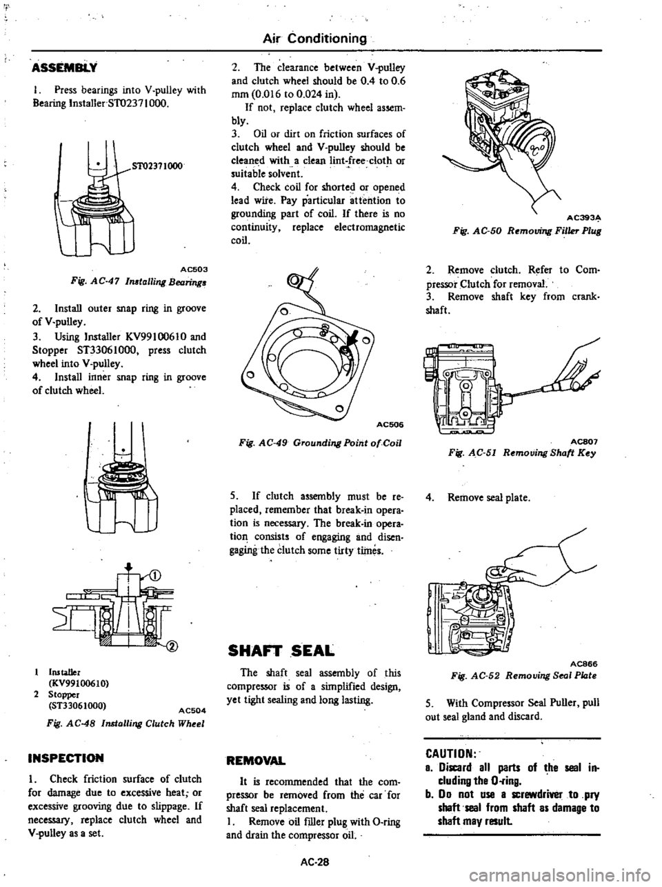
ASSEMBLY
1
Press
bearings
into
V
pulley
with
Bearing
Installer
5T0237
1000
51
02371000
AC503
Fig
AC
47
In
talling
Bearing
2
Install
outer
snap
ring
in
groove
of
V
pulley
3
Using
Installer
KV99l
0061
0
and
Stopper
ST33061000
press
clutch
wheel
into
V
pulley
4
Install
inner
snap
ring
in
groove
of
clutch
wheel
u
Installer
KV99100610
2
Stopper
ST33061000
AC504
Fig
AC
48
Installing
Clutch
Wheel
INSPECTION
I
Check
friction
surface
of
clutch
for
damage
due
to
excessive
heat
or
excessive
grooving
due
to
slippage
If
neceSS3I
replace
clutch
wheel
and
V
pulley
as
a
set
Air
Conditioning
2
The
clearance
between
V
pulley
and
clutch
wheel
should
be
0
4
to
0
6
mm
0
016
to
0
024
in
If
not
replace
clutch
wheel
assem
bly
3
Oil
or
dirt
on
friction
surfaces
of
clutch
wheel
and
V
pulley
should
be
cleaned
with
a
clean
Iint
free
clot
or
suitable
solvent
4
Check
coil
for
shorted
or
opened
lead
wire
Pay
particular
attention
to
grounding
part
of
coil
If
there
is
no
continuity
replace
electromagnetic
coil
Fig
AC
49
Grounding
Point
01
Coil
S
If
clutch
assembly
must
be
re
placed
remember
that
break
in
opera
tion
is
neceSS3I
The
break
in
opera
tion
consists
of
engaging
and
disen
gagingthe
clutch
some
tirty
tlines
SHAFT
SEAL
The
shaft
seal
assembly
of
this
compressor
is
of
a
simplified
design
yet
tight
sealing
and
long
lasting
REMOVAL
It
is
recommended
that
the
com
pressor
be
removed
from
the
car
for
shaft
seal
replacement
I
Remove
oil
filler
plug
with
O
ring
and
drain
the
compressor
oil
AC
28
AC393
Fig
AC
50
Removing
Filler
Plug
2
Remove
clutch
Refer
to
Com
pressor
Clutch
for
removal
3
Remove
shaft
key
from
crank
shaft
L
IJ
C
I
0
ACS07
Fig
AC
51
Removing
Shott
Key
4
Remove
seal
plate
J
e
I
@
IR
n
1
j
AC866
Fig
AC
52
Removing
Seal
Plote
5
With
Compressor
Seal
Puller
pull
out
seal
gland
and
discard
CAUTION
a
iscard
all
parts
of
he
seal
in
cluding
tha
O
ring
b
00
not
use
a
screwdrivel
to
pry
shaft
seal
from
shaft
as
damage
to
shaft
may
result
Page 547 of 548
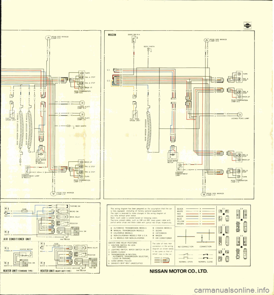
C
E3J
i
I
u
r
o
alNATIO
1
9
fl
l
w
tif
S
lATr
u
N
T
i
0
lf
5f
lAH
8
g
llOOY
AIITI
0
BI
b
RWIPER
IoOODELS
a
RW
LUGGAGf
aD
B
iO
b
n
rNr
lAMP
1
FUSE
1
AIR
CONDnION
R
UNIT
1
lii
I
I
N
UNITCSlAMD
UOTYPEl
I
LAMP
lH
ARKER
Th
ng
diagram
ha
been
fullyeqU1pped
nclod
p
wredontheas
The
ght
IS
e
erv
l
og
all
factory
optIonal
SUmQtron
tllat
the
car
BLACK
any
tme
II
1aut
to
make
chang
s
In
the
eQU
Omefll
Note
EaCh
cao
ro
notICe
l
d
g
am
at
WHITE
D
CI
r
olon
colO
E
d
Ca
Iore
l
ba
ed
on
1011010
ffi
El3
C4
pa
l
a
wh
te
Sl
l
bles
Suel
as
GW
n
8R
g
colors
GREEN
1m
o11Id
blaCk
cao
th
pa
l
I
n
5
at
l@
Il
BLUE
C
AUTOMATIC
fRAN
pe
l
tely
YlilOW
I
MANUAL
TRAN
M
MISSION
MODUS
BROWN
1
CALIFORNIA
MOD
ION
MODELS
A
MODELS
w
w
B
j
NONCAUroRNIA
I
HATCHBACK
It
it
FU
MODEtS
FOR
tS
FOR
USA
WAGON
AllFORN
A
t
AIR
CONDITIONER
SWITCH
AND
RE
J
IGNITION
SWI
Y
POSITIONS
KEY
REMOVEO
IN
lOCII
n
co
o
011
@
1
1
LIGHTING
SWITCH
W
P
con
10
lhe
w
n
g
DOORS
CtoSlO
ER
SWITCH
IN
OFF
TRANSMISSION
m
hown
be
w
NO
CONNECTION
CONNECTION
AUtOMATIC
T
EUTRAl
I
me
th
of
lEVER
IN
PAIU
IN
SSIDN
SlLECfORi
oKlualhne
nthec
HANOBRAIIEPUllEO
t
ffi
III
fi
ORIVEWS
SEAT
BELT
UNOCCUPIED
@
C
JiOR
lOPEN
NORMAL
CLOSE
NISSAN
MOTOR
tl
J
w
iJ
j
II
C
TA
l
SfOP
t
o
L
SlOP
fUPN
lj
ro
elNA
TI
N
JbtJ
1
G
J
W
1
J
ITHERMO
sw
B
H
IMICRO
sw
1
l
n
MA
IN
RELA
V
c
1W231
rAN
SW
I
A
NMOTOR
of
l
I
rr
I
I
I
c
1m231
i
11
II
i
HEATER
UNIT
Mun
DUT
FA
N
J
WAGON
t
o
a
ijE
c
r
g
E3J
FUEl
Tjl
NII
GA
LJGE
UNIT
JL
OODfi
11
tl
DJ
H
t
ow
J
TA
l
BA
CII
UP
rI
O
BlNjl
TIOf
l
J
9
111
fi
l
JID
l
6
o
o
c
II
LICENSE
PLA
TE
LAMP
ijf
I
LUGGAGE
R
r2
ARTMENI
C
ow
Tjl
ll
STOP
IIA
CIIUP
t
C
co
STOP
fURN
n
ro
fBINA
TION
I
J
CO
LTD