remove seats DATSUN 210 1979 Service Manual
[x] Cancel search | Manufacturer: DATSUN, Model Year: 1979, Model line: 210, Model: DATSUN 210 1979Pages: 548, PDF Size: 28.66 MB
Page 44 of 548
5
Fit
insert
ensuring
that
it
seats
on
bottom
face
of
its
recess
6
Newly
fitted
valve
seat
should
be
cut
or
ground
with
suitable
seat
cutter
or
grinding
stone
7
Apply
smalliunount
of
fine
grind
ing
compound
to
valve
contacting
face
and
put
valve
into
guide
Lap
valve
against
its
seat
ntil
proper
valve
seat
ing
is
obtained
Remove
valve
and
clean
valve
and
valve
seat
VALVE
ROCKER
ARM
1
AND
SHAFT
I
Check
rocker
arm
bore
and
shaft
for
scores
or
scuffs
2
Check
clearance
between
each
rocker
arm
and
shaft
by
measuring
inner
diameter
of
rocker
arm
bore
and
outer
diameter
of
shaft
If
either
clearance
is
not
within
spec
ification
replace
rocker
arm
and
or
shaft
3
Check
valve
end
contact
surface
of
rocker
arm
for
abnormal
wear
or
scuffs
VALVE
LIFTER
AND
PUSH
ROD
I
Check
valve
lifter
for
wear
or
scuffs
Check
bottom
end
of
valve
lifter
to
make
sure
it
has
a
slight
convex
Replace
valve
lifters
that
are
scored
worn
or
have
unsmooth
bot
tom
2
Check
clearance
between
lifter
hole
on
cylinder
block
and
valve
lifter
Replace
valve
lifter
if
clearance
ex
ceeds
wear
limit
3
Check
push
rod
for
bending
and
damage
Check
end
of
push
rod
for
rough
ness
or
excessive
wear
CAMSHAFT
AND
CAMSHAFT
BEARING
CAMSHAFT
BEARING
CLEARANCE
Journal
diameters
should
be
check
ed
with
a
micrometer
and
bearings
with
an
inside
dial
gauge
Measure
ments
should
then
be
compared
to
Engine
Mechanical
determine
whether
bearings
are
worn
If
worn
beyond
0
15
mm
0
0059
in
replace
using
Camshaft
Bearing
Drift
STl6Il0000
In
press
fitting
a
new
bearing
make
certain
that
oil
holes
in
block
and
bearing
are
properly
aligned
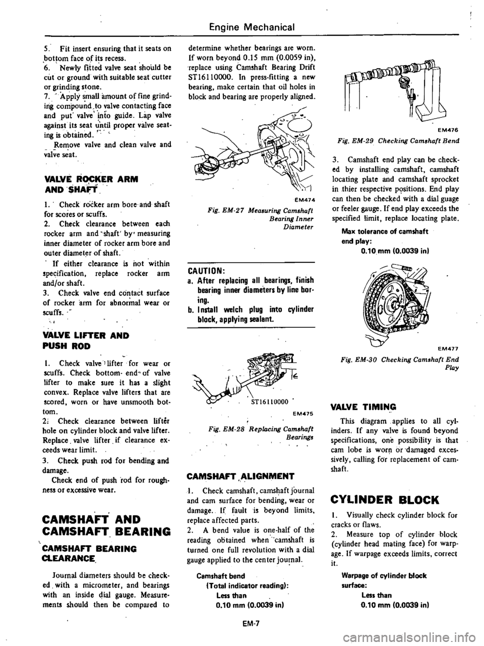
EM474
Fig
EM
27
Measuring
Camshaft
Bearing
Inner
Diameter
CAUTION
a
After
replacing
all
bearings
finish
bearing
inner
diameters
by
line
bor
ing
b
I
nstall
welch
plug
into
cylinder
block
applying
sealant
EM475
Fig
EM
28
Replacing
Cam
haft
Bearings
CAMSHAFT
ALIGNMENT
I
Check
camshaft
camshaft
journal
and
earn
surface
for
bending
wear
or
damage
If
fault
is
beyond
limits
replace
affected
parts
2
A
bend
value
is
one
half
of
the
reading
obtained
when
camshaft
is
turned
one
full
revolution
with
a
dial
gauge
applied
to
the
cen
ter
journal
Camshaft
bend
Total
indicator
reading
Less
than
0
10
mm
0
0039
in
EM
7
s
EM476
Fig
EM
29
Checking
Cam
haft
Bend
3
Camshaft
end
play
can
be
check
ed
by
installing
camshaft
camshaft
locating
plate
and
camshaft
sprocket
in
thier
respective
p
sitions
End
play
can
then
be
checked
with
a
dial
guage
or
feeler
gauge
If
end
play
exceeds
the
specified
limit
replace
locating
plate
Max
tolerance
of
camshaft
end
pley
0
10
mm
0
0039
in
EM477
Fig
EM
3D
Checking
Cam
haft
End
Play
VALVE
TIMING
This
diagram
applies
to
all
cyl
inders
If
any
valve
is
found
beyond
specifications
one
possibility
is
that
earn
lobe
is
worJ
1
or
damaged
exces
sively
calling
for
replacement
of
cam
shaft
CYLINDER
BLOCK
I
Visually
check
cylinder
block
for
cracks
or
flaws
2
Measure
top
of
cylinder
block
cylinder
head
mating
face
for
warp
age
If
warpage
exceeds
limits
correct
it
Warpage
of
cylinder
block
surface
Less
than
0
10
mm
0
0039
in
Page 49 of 548
PRECAUTION
Before
assembling
engine
observe
following
precautions
I
Clean
all
disass
mbled
parts
with
clean
solvent
All
611
holes
in
crank
shaft
camshaft
valve
rocker
shaft
etc
should
be
thoroughly
cleaned
to
re
move
all
traces
of
grinding
chips
or
lint
Always
use
clean
solvent
2
In
general
used
gaskets
packings
and
oil
seals
should
be
replaced
3
Under
no
circumstances
should
lockwashers
be
reuse
d
4
Place
bolts
nuts
and
woshers
back
in
their
original
parts
or
from
which
they
were
removed
5
MOst
packing
Serve
best
when
liquid
packing
is
applied
to
sealing
surfaces
When
desigiiated
use
suitable
liquid
packing
to
eliminate
possibility
of
water
oil
and
gas
leak
6
Prior
to
assemQling
all
sliding
surfaces
should
be
lioerally
oiled
7
Proper
tightening
is
essential
to
successful
performanCe
of
all
car
re
pairs
It
is
also
important
to
follow
correct
tightenig
sequence
in
pulling
up
cylinder
head
Be
on
alert
at
all
times
to
amount
of
clearance
per
mitted
8
Cleanliness
of
tools
or
parts
such
as
work
bench
used
jn
making
a
repai
is
essential
When
setting
up
a
job
every
precaution
should
be
taken
that
tools
or
parts
are
free
of
dirt
mud
and
oil
Do
not
work
in
dust
and
grit
for
they
are
primary
cause
of
wear
in
any
engine
CYLINDER
HEAD
I
Install
valve
spring
seat
Install
valve
oil
seal
by
lightly
tapping
its
head
with
a
plastic
hammer
through
Valve
Lip
Seal
Drift
KVI0104800
Engine
Mechanical
ENGINE
ASSEMBLY
m
f
if
@
@
4
1
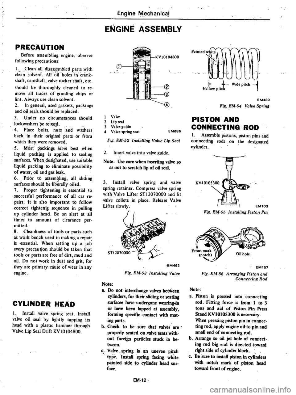
Valve
2
Lip
seal
3
Valve
guide
4
Valve
spring
seat
EM688
Fig
EM
52
tailing
Valve
Lip
Seal
2
Insert
valve
into
valve
guide
Note
Use
care
when
inserting
valve
so
as
not
to
scratch
lip
of
oil
seal
3
Install
valve
spring
and
valve
spring
retainer
Compress
valve
pring
with
Valve
Lifter
STl2070000
and
fit
valve
collets
in
place
Release
Valve
Lifter
slowly
EM462
Fig
EM
53
Inatalling
Valve
Note
8
Do
not
interchange
valves
between
cylinders
for
their
sliding
or
seating
surfaces
have
undergone
wearing
in
or
have
been
lapped
at
assembly
forming
specific
contact
with
mat
ing
parts
b
Check
to
be
sure
that
valves
are
properly
seated
on
valve
seats
with
out
foreign
particles
stuck
in
be
tween
c
Valve
spring
is
an
uneven
pitch
type
Install
spring
facing
Wte
painted
side
to
cylinder
head
sur
face
EM
12
p
lOted
l
rJF
t
A
J
il
j
j
Wide
pilCh
l
Nallow
pitch
I
EM489
Fig
EM
54
Valve
Spring
PISTON
AND
CONNECTING
ROD
I
Assemble
pistons
piston
pins
and
connecting
rods
on
the
designated
cylinder
EM103
Fig
EM
55
Installing
Piston
Pin
EM157
Fig
EM
56
Arranging
Piaton
and
Connecting
Rod
Note
3
Piston
is
pressed
into
connecting
rod
Fitting
force
is
from
1
to
3
tons
and
aid
of
Piston
Pin
Press
Stand
KVI
01
05300
is
necessary
When
pressing
piston
pin
in
connec
ting
rod
apply
engine
oil
to
pin
and
small
end
of
connecti
8
rod
b
Arrange
so
oil
jet
hole
of
connect
ing
rod
big
end
is
directed
toward
right
side
of
cylinder
block
c
Be
Sure
to
install
piston
in
cylinders
with
notch
mark
of
piston
head
toward
front
of
engine
Page 331 of 548
FA070
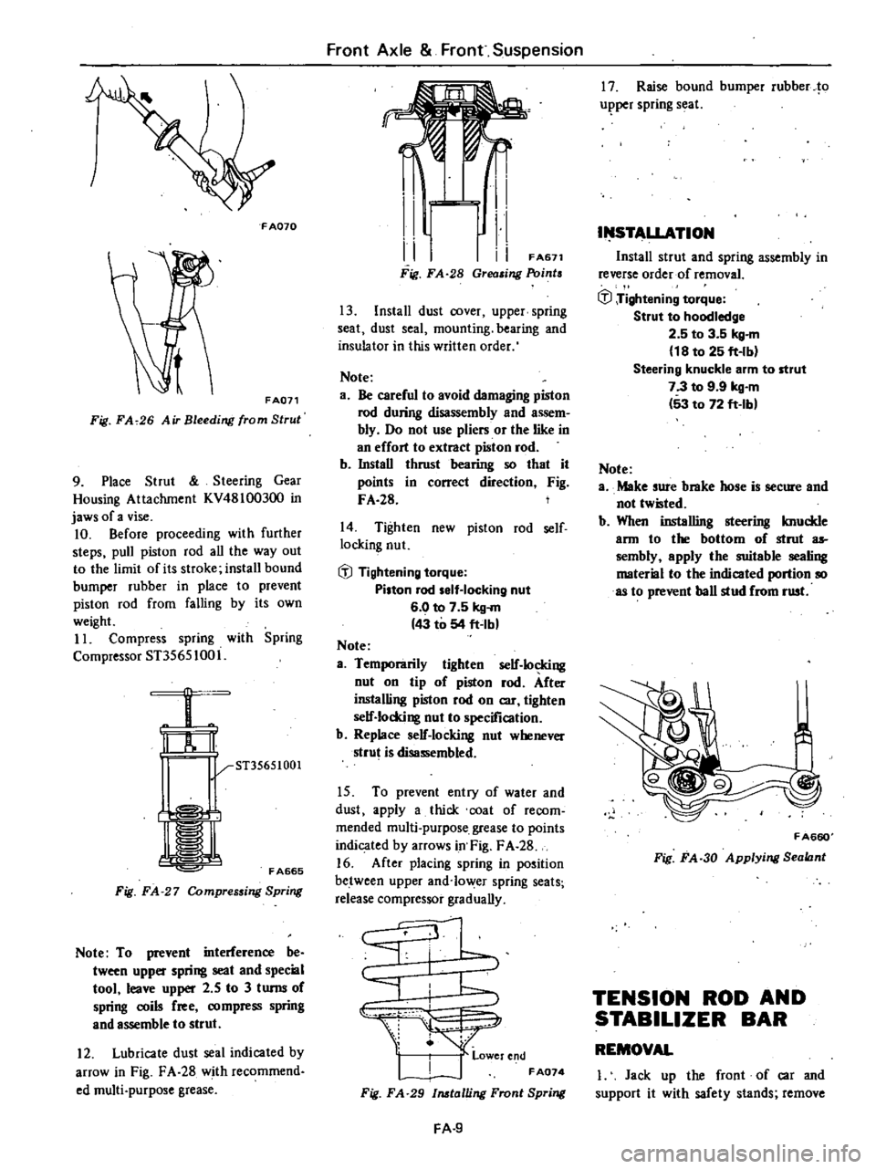
FA071
Fig
FA
26
Air
Bleeding
from
Strul
9
Place
Strut
Steering
Gear
Housing
Attachment
KV48100300
in
jaws
of
a
vise
10
Before
proceeding
with
further
steps
pull
piston
rod
all
the
way
out
to
the
limit
of
its
stroke
install
bound
bumper
rubber
in
place
to
prevent
piston
rod
from
falling
by
its
own
weight
11
Compress
spring
with
Spring
Compressor
ST35651001
ST35651001
r
l
I
FA665
Fig
FA
27
Compressing
Spring
Note
To
prevent
interference
be
tween
upper
spring
seat
and
special
tool
leave
upper
2
5
to
3
turns
of
spring
coils
free
compress
spring
and
assemble
to
strut
12
Lubricate
dust
seal
indicated
by
arrow
in
Fig
FA
28
with
recommend
ed
multi
purpose
grease
Front
Axle
Front
Suspension
I
1
i
I
FA671
Fig
FA
28
Grea
ing
Point
13
Install
dust
cover
upper
spring
seat
dust
seal
mounting
bearing
and
insulator
in
this
written
order
Note
a
Be
careful
to
avoid
damaging
piston
rod
during
disassembly
and
assem
bly
Do
not
use
pliers
or
the
like
in
an
effort
to
extract
piston
rod
b
InstaU
thrust
bearing
so
that
it
points
in
correct
direction
Fig
FA
28
14
Tighten
new
piston
rod
self
locking
nut
fil
Tightening
torque
Pi
ton
rod
elf
Iocking
nut
6
0
to
7
5
kg
m
43
to
54
ft
lbl
Note
a
Temporarily
tighten
self
locking
nut
on
tip
of
piston
rod
After
installing
piston
rod
on
car
tighten
self
locking
nut
to
specification
b
Replace
self
locking
nut
whenever
strut
is
disassembled
15
To
prevent
entry
of
water
and
dust
apply
a
thick
coat
of
recom
mended
multi
purpose
grease
to
points
indicated
by
arrows
in
Fig
F
A
28
16
After
placing
spring
in
position
between
upper
and
lo
er
spring
seats
release
compressor
graduaUy
I
J
k
1
jt
r
end
FA074
Fig
FA
29
talling
Front
Spring
FA
9
17
Raise
bound
bumper
rubber
10
u
per
spring
seal
I
STALLATION
Install
strut
and
spring
assembly
in
reverse
order
of
removaL
fil
Tightening
torque
Strut
to
hoodledge
2
5
to
3
5
kg
m
18
to
25
ft
Ib
Steering
knuckle
arm
to
strut
7
3
to
9
9
kg
m
53
to
72
ft
lb
Note
a
Make
sure
brake
hose
is
secure
and
not
tw
ted
b
When
installing
steering
knuckle
ann
to
the
bottom
of
strut
as
sembly
epply
the
suitable
sealing
material
to
the
indicated
portion
so
as
to
prevent
ball
stud
from
rust
FA660
Fig
FA
30
Applying
Sealant
TENSION
ROD
AND
STABILIZER
BAR
REMOVAL
I
Jack
up
the
front
of
car
and
support
it
with
safety
stands
remove
Page 380 of 548
The
symptom
of
unbalance
appears
as
tramps
car
shake
and
steering
mal
function
To
correct
unbalance
use
proper
wheel
balancer
Maximum
allowable
unbalance
at
rim
flange
10
gr
10
35
ozl
Balance
weight
10
to
60
gr
10
35
to
2
12
ozl
at
10
gr
10
35
ozl
interval
Note
a
Be
sure
to
place
correct
balance
weights
on
inner
edge
of
rim
See
Fig
wr
6
b
Do
not
put
mOle
than
two
weights
on
each
side
c
Two
types
of
balance
weights
are
used
one
is
designed
for
use
with
steel
wheel
and
the
other
for
use
with
aluminum
wheel
Do
not
mix
different
types
of
balance
weights
WHEEL
In
order
to
ensure
satisfactory
steering
condition
as
well
as
maximum
tire
life
proceed
follows
Check
wheel
rim
especially
rim
flange
and
bead
seat
for
rust
distor
tion
cracks
or
other
faults
which
might
cause
air
leaks
Function
of
tubeless
tire
depends
on
a
good
seal
between
tire
bead
and
wheel
rim
Thoroughly
remove
rust
dust
oxi
dized
rubber
or
sa
nd
from
wheel
rim
Note
Rim
bead
seats
should
be
clean
ed
with
the
following
Steel
wheel
Wile
brush
coone
steel
wool
etc
Aluminum
wheel
Neutral
detergent
cloth
etc
Use
dial
gauge
to
examine
wheel
rim
for
lateral
and
radial
runout
Wheel
and
Tire
Lateral
and
radial
runout
Steel
wheel
less
than
1
2
mm
0
047
in
Aluminumwlte
1
lass
than
0
5
mm
10
020
in
Difference
right
and
left
lateral
runout
Steel
wheel
leu
than
0
5
mm
10
020
in
Aluminum
wheel
less
than
0
2
mm
0
008
in
C
JeCk
points
l
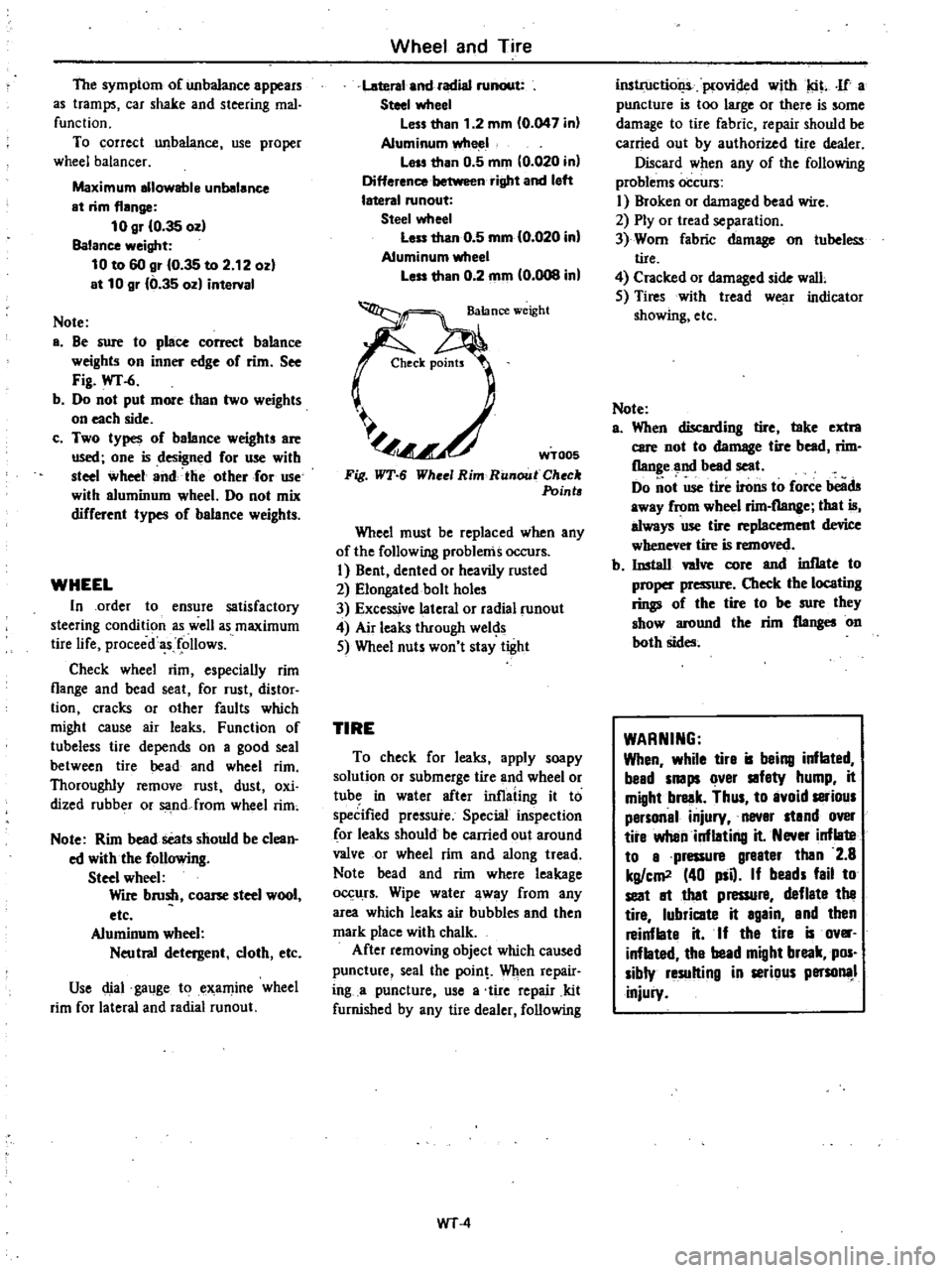
Fig
WT
6
WT005
Whee
Rim
RUllout
Check
Points
Wheel
must
be
replaced
when
any
of
the
following
problems
occurs
I
Bent
dented
or
heavily
rusted
2
Elongated
bolt
holes
3
Excessive
lateral
or
radial
runout
4
Air
leaks
through
wel
s
5
Wheel
nuts
won
t
stay
tight
TIRE
To
check
for
leaks
apply
soapy
solution
or
submerge
tire
and
wheel
or
tub
in
water
after
inflating
it
to
speCified
pressure
Special
inspection
for
leaks
should
be
carried
out
around
valve
or
wheel
rim
and
along
tread
Note
bead
and
rim
where
leakage
0
11rs
Wipe
water
away
from
any
area
which
leaks
air
bubbles
and
then
mark
place
with
chalk
After
removing
object
which
caused
puncture
seal
the
pain
Wilen
repair
ing
a
puncture
use
a
tire
repair
kit
furnished
by
any
tire
dealer
following
WT
4
inslrt1ctiol
iplovided
with
tit
If
a
puncture
is
too
large
or
there
is
some
damage
to
tire
fabric
repair
should
be
carried
out
by
authorized
tire
dealer
Discard
when
any
of
the
following
problems
occurs
I
Broken
or
damaged
bead
wire
2
Ply
or
tread
separation
3
Worn
fabric
damage
on
tubeless
tire
4
Cracked
or
damaged
side
wall
5
Tires
with
tread
wear
indicator
showing
etc
Note
a
When
discarding
tire
take
extra
care
not
to
damage
tire
bead
rim
flange
and
bead
seat
Do
ot
use
tire
irons
to
foree
beads
away
from
wbeel
rim
flange
that
is
always
use
tire
replacement
device
whenever
tire
is
removed
b
Install
wive
core
and
inflate
to
proper
pressure
Check
the
locating
rings
of
the
tire
to
be
sure
they
show
around
the
rim
flanges
on
both
sides
WARNING
When
while
tire
is
being
inflated
bead
snaps
over
safety
hump
it
might
break
Thus
to
avoid
satious
personal
injury
never
stand
over
tire
when
inflating
it
Never
inflate
to
a
pressure
greater
then
2
8
kg
em
40
psQ
If
beads
fail
to
seat
It
that
pressure
deflate
the
tire
lubricate
it
again
and
then
reinflate
it
If
the
tire
is
ov
inflated
the
bead
might
break
pos
sibly
resulting
in
serious
persona
injury
Page 432 of 548
Body
WINDSHIELD
AND
WINDOW
GLASS
WINDSHIELD
GLASS
00
REMOVAL
I
Place
a
protective
cover
over
hood
front
fenders
instrument
panel
and
front
seats
2
Remove
windshield
wiper
arm
as
semblies
3
Remove
windshield
moldings
4
On
inside
of
body
loosen
lip
of
weatherstrip
from
body
flange
along
top
and
sides
of
windshield
opening
Use
a
conventional
screwdriver
and
carefully
put
weatherstrip
over
body
flange
BF5618
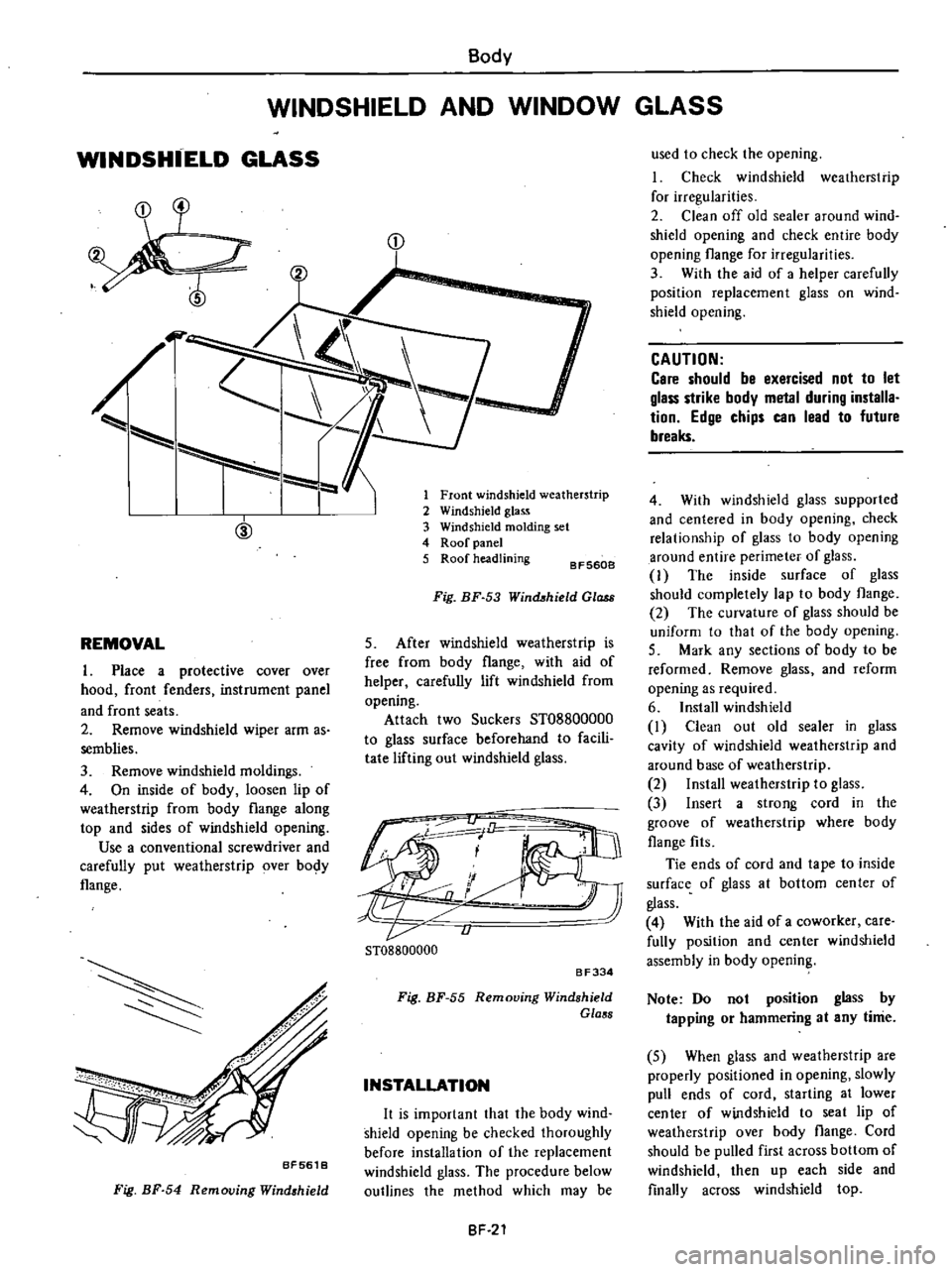
Fig
BF
54
Removing
Wind
hield
D
1
Front
windshield
weatherstrip
2
Windshield
glass
3
Windshield
molding
set
4
Roof
panel
5
Roof
headlining
BF5608
Fig
BF
53
Winct
hield
Ol
5
After
windshield
weatherstrip
is
free
from
body
flange
with
aid
of
helper
carefully
lift
windshield
from
opening
Attach
two
Suckers
ST08800000
to
glass
surface
beforehand
to
facili
tate
lifting
out
windshield
glass
Li
ST08800000
BF334
Fig
BF
55
Removing
Windshield
Glass
INSTALLATION
It
is
important
that
the
body
wind
shield
opening
be
checked
thoroughly
before
installation
of
the
replacement
windshield
glass
The
procedure
below
outlines
the
method
which
may
be
BF
21
used
to
check
the
opening
I
Check
windshield
weatherstrip
for
irregularities
2
Clean
off
old
sealer
around
wind
shield
opening
and
check
entire
body
opening
flange
for
irregularities
3
With
the
aid
of
a
helper
carefully
position
replacement
glass
on
wind
shield
opening
CAUTION
Care
should
be
exercised
not
to
let
glass
strike
body
metal
during
installa
tion
Edge
chips
can
lead
to
future
breaks
4
With
windshield
glass
supported
and
centered
in
body
opening
check
relationship
of
glass
to
body
opening
around
entire
perimeter
of
glass
I
The
inside
surface
of
glass
should
completely
lap
to
body
flange
2
The
curvature
of
glass
should
be
uniform
to
that
of
the
body
opening
5
Mark
any
sections
of
body
to
be
reformed
Remove
glass
and
reform
opening
as
required
6
Install
windshield
I
Clean
out
old
sealer
in
glass
cavity
of
windshield
weatherstrip
and
around
base
of
weatherstrip
2
Install
weatherstrip
to
glass
3
Insert
a
strong
cord
in
the
groove
of
weatherstrip
where
body
flange
fits
Tie
ends
of
cord
and
tape
to
inside
surface
of
glass
at
bottom
center
of
glass
4
With
the
aid
of
a
coworker
care
fully
position
and
center
windshield
assembly
in
body
opening
Note
Do
not
position
glass
by
tapping
or
hammering
at
any
time
5
When
glass
and
weatherstrip
are
properly
positioned
in
opening
slowly
pull
ends
of
cord
starting
at
lower
center
of
windshield
to
seat
lip
of
weatherstrip
over
body
flange
Cord
should
be
pulled
first
across
bottom
of
windshield
then
up
each
side
and
finally
across
windshield
top