engine coolant DATSUN 210 1979 Service Manual
[x] Cancel search | Manufacturer: DATSUN, Model Year: 1979, Model line: 210, Model: DATSUN 210 1979Pages: 548, PDF Size: 28.66 MB
Page 15 of 548
DATSUN
210
Model
8310
Series
SECTIONET
ET
ENGINE
TUNE
UP
CONTENTS
EMISSION
CONTROL
DEVICES
BASIC
MECHANICAL
SYSTEM
ADJUSTING
INTAKE
AND
EXHAUST
VALVE
CLEARANCE
CHECKING
AND
ADJUSTING
DRIVE
BELTS
CHANGING
ENGINE
OIL
REPLACING
01
L
FI
L
TER
CHANGING
ENGINE
COOLANT
CHECKING
COOLING
SYSTEM
HOSES
AND
CONNECTIONS
CHECKING
ENGINE
COMPRESSION
IGNITION
AND
FUEL
SYSTEM
CHECKING
BATTERY
CHECKING
AND
ADJUSTING
IGNITION
TIMING
CHECKING
IGNITION
WIRING
CHECKING
AND
REPLACING
SPARK
PLUGS
CHECKING
AND
ADJUSTING
CARBURETOR
IDLE
RPM
AND
MIXTURE
RATIO
CHECKING
CHOKE
MECHANISM
Choke
plate
and
linkage
CHECKING
FUEL
SHUT
OFF
SYSTEM
FU
models
ET
2
ET
3
ET
3
ET
3
ET
3
ET
3
ET
4
ET
4
ET
4
ET
5
ET
5
ET
5
ET
6
ET
6
ET
7
ET
9
ET
9
REPLACING
FUEL
FILTER
ET
10
CHECKING
FUEL
LINES
Hoses
piping
connections
etc
ET
10
REPLACING
AIR
CLEANER
FILTER
ETlO
CHECKING
AUTOMATIC
TEMPERATURE
CONTROL
AIR
CLEANER
ET
10
EMISSION
CONTROL
SYSTEM
ET
11
CHECKING
VACUUM
FITTING
HOSES
AND
CONNECTIONS
ET
11
REPLACING
AIR
PUMP
AIR
CLEANER
FILTER
Except
FU
models
and
Canada
models
E
1122i
REPLACING
AIR
INDUCTION
VALVE
FILTER
FU
models
and
Canada
models
E
tlil1r2
C
REPLACING
PCV
VALVE
AND
FILTER
ETf
CHECKING
VENTI
LATION
HOSES
E1P12
CHECKING
VAPOR
LINES
Eli
J2
CHECKING
FUEL
TANK
VACUUM
RELIEF
I
f
III
VALVE
ET
13
REPLACING
CARBON
CANISTER
W
FILTER
ET
d
SERVICE
DATA
AND
SPECIFICATIONS
ET
14
TROUBLE
DIAGNOSES
AND
CORRECTIONS
ET
16
SPECIAL
SERVICE
TOOL
ET
23
Page 18 of 548
pl
ice
mter
as
an
assembly
2
When
installing
oil
mter
tighten
by
hand
Note
Do
not
overtighten
oil
filter
lest
leakage
shoUld
occur
CHANGING
ENGINE
COOLANT
PERMANENT
ANTI
FREEZE
COOLANT
Note
The
permanent
anti
freeze
coolant
is
an
ethylene
glya
l
base
product
containing
chemical
in
hibitors
to
protect
the
cooling
system
from
rusting
and
corrosion
The
anti
freeze
does
not
cOntain
any
glycerine
or
ethyl
alcohol
It
will
not
evaporate
or
boil
a
ay
and
can
be
ilsed
with
either
high
or
low
temperature
thermostats
It
flows
freely
transfers
heat
efficiently
and
will
not
clog
the
passages
in
the
cooling
system
The
anti
freeze
must
not
be
mixed
with
other
product
This
coolant
can
be
used
throughout
the
seasons
of
the
year
Whenever
coolant
is
changed
the
cooling
system
must
be
flushed
and
refilled
with
a
new
coolant
Check
the
coolant
level
See
instructions
attached
to
the
anti
freeze
container
for
mixing
ratio
of
anti
freeze
to
water
CHECKING
COOLING
SYSTEM
HOSES
AND
CONNECTIONS
Check
hoses
and
fittings
for
loose
connections
or
deterioration
Re
tighten
or
replace
if
necessary
INSPECTION
OF
RADIATOR
CAP
Apply
reference
pressure
0
9
kgj
cm2
13
psi
to
radiator
cap
by
means
of
a
cap
tester
to
see
if
it
is
satisfactory
Replace
cap
assembly
if
necessary
I
j
ngine
Tune
up
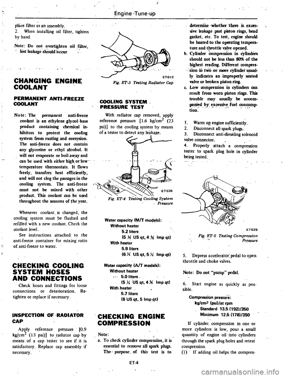
ET012
Fig
ET
3
Testing
Radiator
Cap
COOLING
SYSTEM
PRESSURE
TEST
Witli
radiator
cap
removed
apply
reference
pressure
1
6
kgfcm2
23
psi
to
the
cooling
system
by
means
0
no
Fig
ET
4
Water
capacity
M
Tmodelsl
Without
heater
5
2
liten
5
1f
US
qt
4
Imp
qt
With
heeter
5
9
Iiten
6
4
US
qt
5
Y
Imp
qt
Water
capacity
AfT
modelsl
Without
heater
5
0
liters
5
y
US
qt
4
Imp
qt
With
heater
5
7
liten
6
US
qt
5
Imp
ill
CHECKING
ENGINE
COMPRESSION
Note
a
To
check
cylinder
compression
it
is
essential
to
remove
all
spark
plugs
The
purpose
of
this
test
is
to
ET
4
determine
whether
there
is
exces
sive
leakage
past
piston
rings
head
gasket
etc
To
test
engine
should
be
heated
to
the
operating
t
M
ture
and
throttle
valve
opened
b
Cylinder
compre
on
in
Cylinders
should
not
be
less
than
llO
of
the
highest
reading
Different
compres
sion
in
two
ore
more
cYlinder
usual
ly
indicates
an
improperly
seated
valve
or
broken
piston
ring
c
Low
compression
in
cylinders
am
result
from
worn
piston
rings
This
trouble
may
usuaDy
be
accom
panied
by
ex
ssive
fuel
consump
tion
I
Warm
up
engine
sufficiently
2
Disconnect
aU
spark
plugs
3
Disconnect
anti
dieseling
solenoid
valve
connector
4
Properly
attach
a
compression
tester
to
spark
plug
hole
in
cylinder
being
tested
FiI
ET
S
ET529
Testing
Compre
sion
Pr
s8ure
5
Depress
accelenit6r
pedal
to
open
throttle
and
choke
valves
Note
Do
not
pump
pedal
6
Start
engine
as
quickly
as
pos
sible
Compression
pressllre
kg
cm2
ii
at
rpm
Standard
13
5
192
350
Minimum
12
5
1781
350
If
cylinder
compression
in
o
e
or
more
cylinders
is
low
pour
a
small
quantity
of
engine
oil
into
cylinders
through
the
spark
plug
holes
and
retest
compression
I
If
addingoil
helps
the
compres
Page 33 of 548
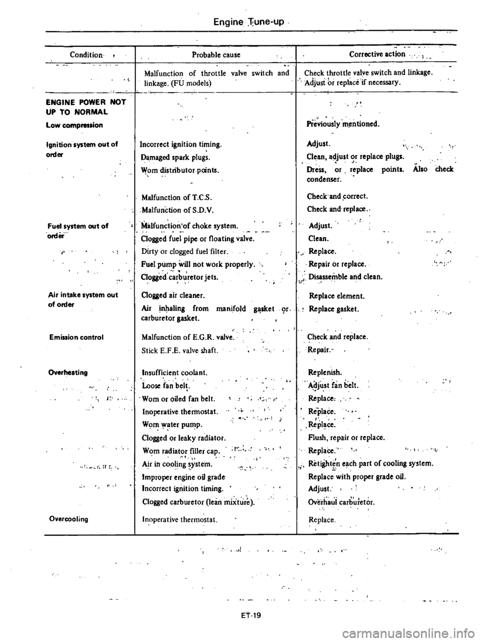
Condition
ENGINE
POWER
NOT
UP
TO
NORMAL
Low
compmsion
Ignition
system
out
of
order
Fuel
system
out
of
order
Air
intake
system
out
of
order
Emission
control
Overheating
J
f
H
r
Overcooling
Engine
liune
up
Probable
cause
Malfunction
of
throttle
valve
switch
and
linkage
FU
models
Incorrect
ignition
timing
Damaged
spark
plugs
Wom
distributor
points
Malfunction
of
T
C
S
cMalfunction
of
S
D
V
Milfunction
of
choke
system
Clogged
fuel
pipe
or
floating
valve
Dirty
or
clogged
fuel
filter
Fuel
pump
will
not
work
properly
Clogged
carb
retor
jets
Clogged
air
cleaner
Air
aling
from
manifold
g
sket
r
carburetor
gasket
Malfunction
of
E
G
R
valve
Stick
E
F
E
valve
shaft
Insufficient
coolant
Loose
fan
bel
Wom
or
oiled
fan
belt
Inoperative
therinostat
Wom
ater
pu
p
Clogged
or
leaky
radiator
Wom
radiator
filler
ca
Air
in
cooling
ystein
Improper
engine
oil
grade
Incorrect
ignition
timing
Clogged
carburetor
lean
miiture
Inoperative
thermostat
1
ET
19
Corrective
action
Check
throttle
valve
switch
and
linkage
Adjusi
i
r
replace
if
necessary
Previously
m
entioned
Adjust
Clean
adjust
or
replace
plugs
Dress
or
replace
points
Also
check
condenser
Check
and
correct
Check
and
replace
Adjust
Clean
Replace
Repair
or
replace
t
J
Disassemble
and
clean
Replace
element
Replace
gasket
Check
and
replace
Repair
Replenish
Adjust
fan
belt
Replace
Replace
Repl
ce
Flush
repair
or
replace
ReplaCe
Retightin
e
ch
part
of
cooling
system
Replace
with
proper
grade
oil
Adjust
Overhaui
carburetor
Replace
Page 80 of 548
DESCRIPTION
The
cooling
system
is
of
the
con
ventional
pressure
type
A
centrifugal
1P
a
COOLANT
LEVEL
Pour
coolant
into
the
radiator
up
to
the
cap
and
also
into
the
reservoir
up
to
the
MAX
level
CAUTION
To
avoid
serious
personal
injury
never
remove
radiator
cap
quickly
when
engine
is
hot
Sudden
release
of
cool
ing
system
pressure
is
very
dangerous
If
it
is
necessary
to
remove
radiator
cap
when
radiator
is
hot
turn
cap
slowly
counterclockwise
to
the
first
step
After
all
pressure
in
the
cool
ing
system
is
released
turn
cap
passing
the
stop
and
remove
it
DRAINING
AND
FLUSHING
THE
COOLING
SYSTEM
To
drain
the
cooling
system
re
move
radiator
cap
release
drain
cock
C09ling
System
COOLING
SYSTEM
pump
installed
on
the
timing
chain
cover
serves
to
circulate
the
coolant
The
pressure
t
pe
radiator
filler
cap
at
the
bottom
of
radiator
and
drain
plug
on
the
left
side
of
cylinder
block
If
the
heater
system
is
instaDed
set
heater
control
valve
to
open
position
Mter
the
coolant
is
drained
complete
ly
close
drain
cock
and
plug
and
refdl
the
system
with
clean
soft
water
WATER
PUMP
The
water
pump
is
of
a
centrifugal
type
which
is
mounted
on
the
engine
front
cover
TJ
te
pump
shaft
is
sup
ported
by
a
double
row
of
baD
bear
ings
press
fit
in
an
aluminum
die
cast
pump
body
The
bearings
are
per
manently
lubricated
and
sealed
to
pre
vent
loss
of
lubricant
and
entry
of
dirt
CO
2
installed
on
the
radiator
operates
the
cooling
system
at
higher
than
atmos
pheric
pressure
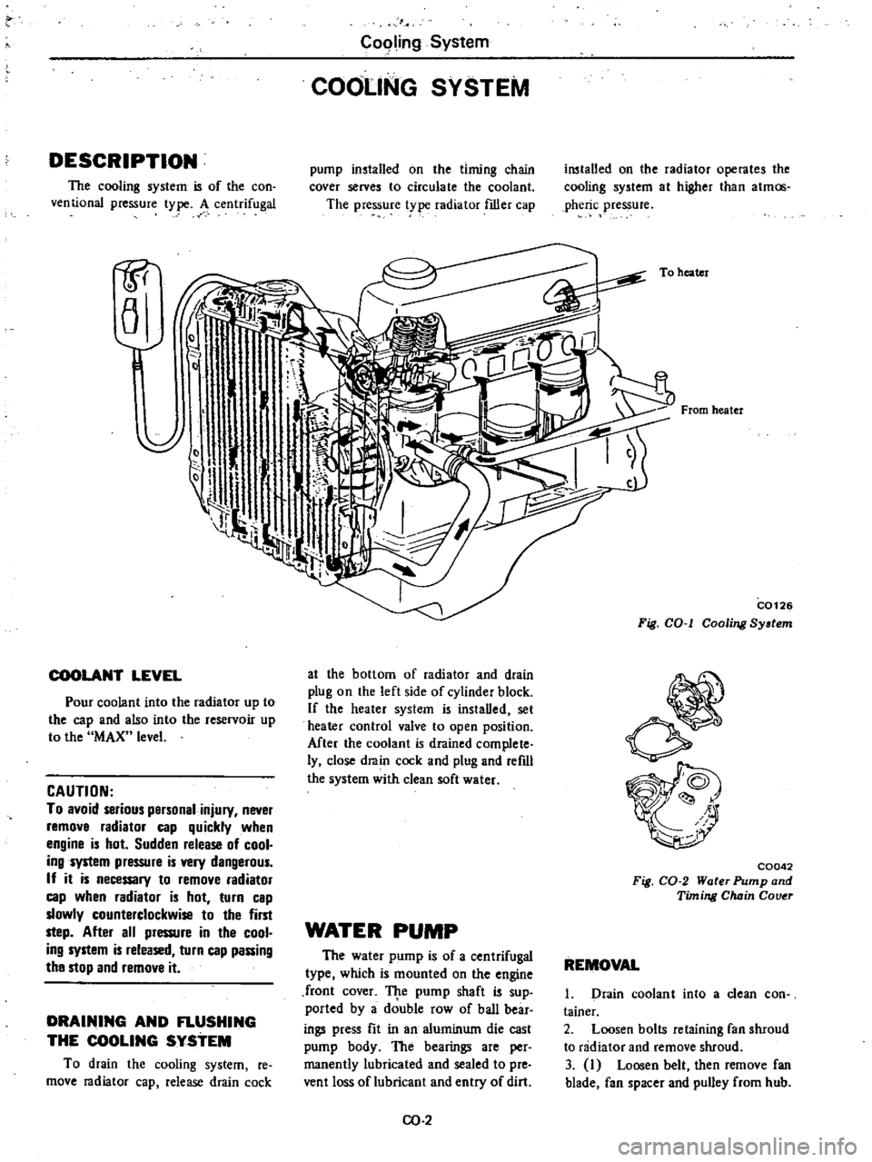
To
heater
From
heater
C0126
Fig
COol
Cooling
System
C0042
Fig
CO
2
Water
Pump
and
Timing
Chain
Couer
REMOVAL
1
Drain
coolant
into
a
clean
con
tainer
2
Loosen
bolts
retaining
fan
shroud
to
radiator
and
remove
shroud
3
I
Loosen
belt
then
remove
fan
blade
fan
spacer
and
pulley
from
hub
Page 82 of 548
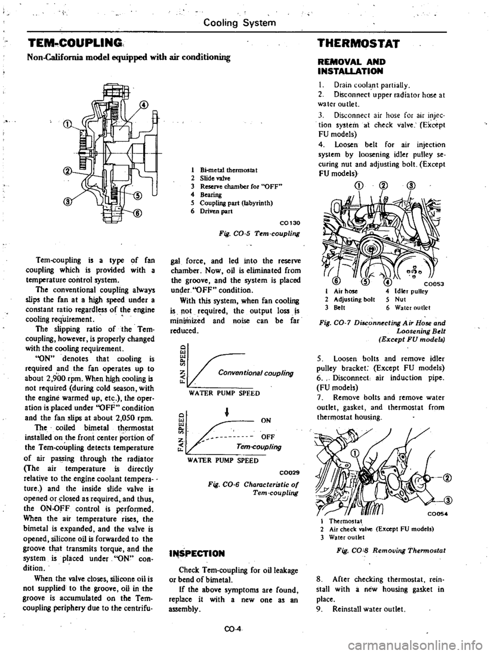
Cooling
System
TEM
COUPLlNG
Non
Califomia
model
equipped
with
air
conditioning
Tem
coupling
is
a
type
of
fan
coupling
which
is
provided
with
a
temperature
control
system
The
conventional
coupling
always
slips
the
fan
at
a
high
speed
under
a
constant
ratio
regardless
of
the
engine
cooling
requirement
The
slipping
ratio
of
the
Tem
coupling
however
is
properly
changed
with
the
cooling
requirement
ON
denotes
that
cooling
is
required
and
the
fan
operates
up
to
about
2
900rpm
When
high
cooling
is
not
required
during
cold
season
with
the
engine
warmed
up
etc
the
oper
ation
is
placed
under
OFF
condition
and
the
fan
slips
at
about
2
050
rpm
The
coiled
bimetal
thermostat
installed
on
the
front
center
portion
of
the
Tem
coupling
detects
temperature
of
air
passing
through
the
radiator
The
air
temperature
is
directly
relative
to
the
engine
coolant
tempera
ture
and
the
inside
slide
valve
is
opened
or
closed
as
required
and
thus
the
ON
OFF
control
is
performed
When
the
air
temperature
rises
the
bimetal
is
expanded
and
the
valve
is
opened
silicone
oil
is
forwarded
to
the
groove
that
transmits
torque
and
the
system
is
placed
under
ON
con
dition
When
the
valve
closes
silicone
oil
is
not
supplied
to
the
groove
oil
in
the
groove
is
accumulated
on
the
Tem
coupling
periphery
due
to
the
centrifu
1
Bi
metal
thermostat
2
Slide
valve
3
Reserve
chamber
fOl
OFF
4
Bearing
5
Coupling
part
labyrinth
6
Driven
part
C0130
Fig
CO
5
Tem
coupling
gal
force
and
led
into
the
reserve
chamber
Now
oil
is
eliminated
from
the
groove
and
the
system
is
placed
under
OFF
condition
With
this
system
when
fan
cooling
is
not
required
the
output
loss
IS
miniinized
and
noise
can
be
far
reduced
Q
i
tionalCOUPling
WATER
PUMP
SPEED
Q
ON
OFF
Tem
coupling
WATER
PUMP
SPEED
C0029
Fig
CO
6
Characteristic
of
Tern
coupling
I
SPECTION
Check
Tem
coupling
for
oil
leakage
or
bend
of
bimetaL
If
the
above
symptoms
are
found
replace
it
with
a
new
one
as
an
assembly
CO
4
THERMOSTAT
REMOVAL
AND
INSTALLATION
I
Drain
cool
nt
partiaUy
2
Disconnect
upper
radiator
hose
at
water
outlet
3
Disconnect
air
hose
for
air
injec
tion
systein
at
check
valve
Fxcept
FU
models
4
Loosen
belt
for
air
injechon
system
by
loosening
idler
pulley
se
curing
nut
and
adjusting
bolt
Except
FU
models
CD
@
ID
I
2
3
C0053
Idler
pulley
Nut
Water
outlet
Fig
CO
7
Disconnecting
Air
Hose
and
Loosening
Belt
Except
FU
models
5
Loosen
bolts
and
remove
idler
pulley
bracket
Except
FU
models
6
Disconnect
air
induction
pipe
FU
models
7
Remove
bolts
and
remove
water
outlet
gasket
and
thermostat
from
thermostat
housing
I
Thermostat
2
Air
check
valve
Except
FU
models
3
Water
outlet
Fig
CO
Removing
Thennostat
8
After
checking
thermostat
rein
stall
with
a
new
housing
gasket
in
place
9
Reinstall
water
outlet
Page 83 of 548
10
Replenish
coolant
and
check
for
leaks
INSPECTION
I
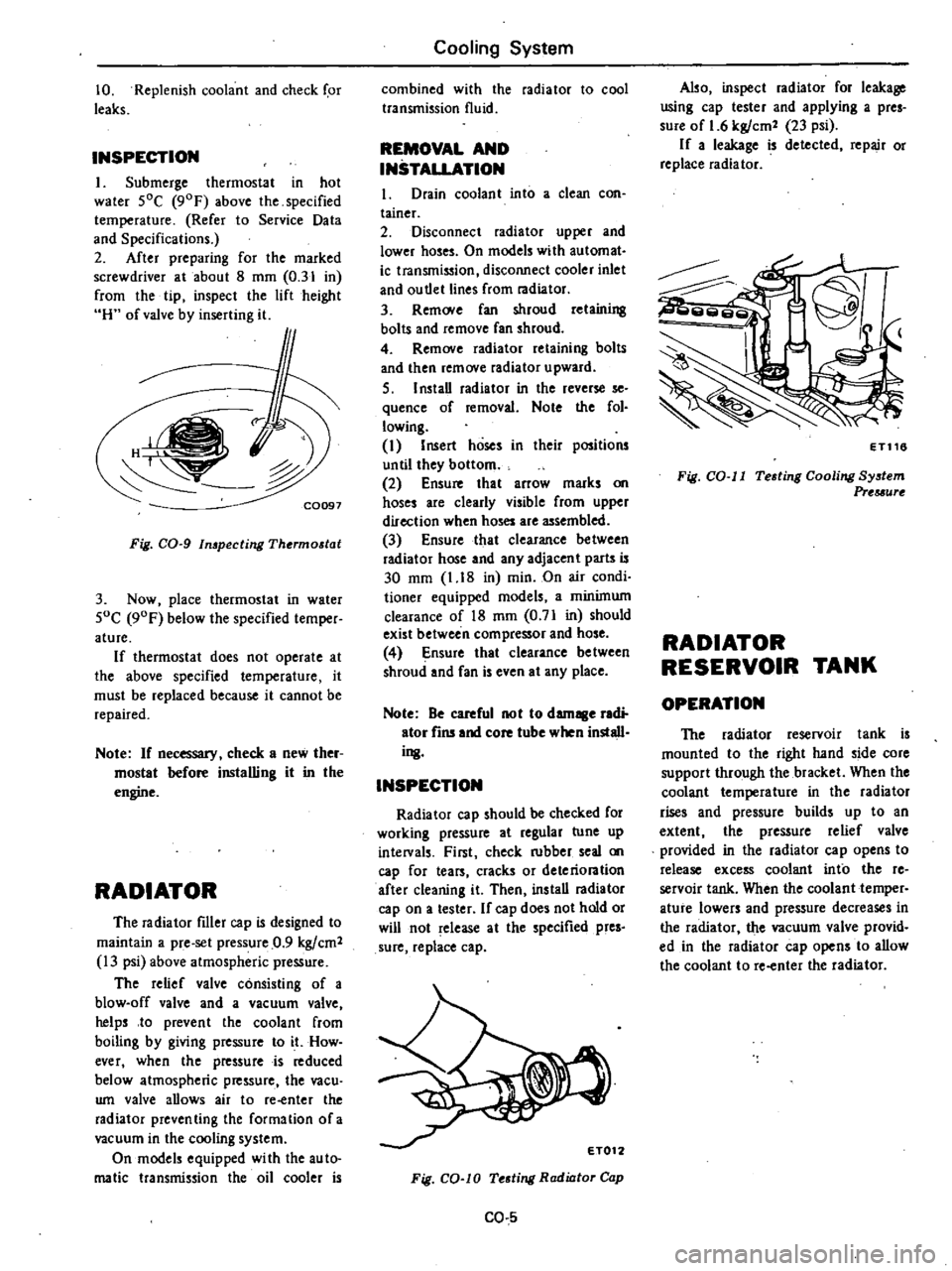
Submerge
thermostat
in
hot
water
SOC
90F
above
the
specified
temperature
Refer
to
Service
Data
and
Specifications
2
After
preparing
for
the
marked
screwdriver
at
about
8
mm
0
31
in
from
the
tip
inspect
the
lift
height
H
of
valve
by
inserting
it
f
C0097
Fig
CO
g
In
pecting
Thermostat
3
Now
place
thermostat
in
water
SoC
90F
below
the
specified
temper
ature
If
thermostat
does
not
operate
at
the
above
specified
temperature
it
must
be
replaced
because
it
cannot
be
repaired
Note
If
necessary
check
a
new
ther
mostat
before
installing
it
in
the
engine
RADIATOR
The
radiator
filler
cap
is
designed
to
maintain
a
pre
set
pressure
0
9
kgfcm2
13
psi
above
atmospheric
pressure
The
relief
valve
consisting
of
a
blow
off
valve
and
a
vacuum
valve
helps
to
prevent
the
coolant
from
boiling
by
giving
pressure
to
it
How
ever
when
the
pressure
is
reduced
below
atmospheric
pressure
the
vacu
wn
valve
allows
air
to
re
enter
the
radiator
preventing
the
formation
ofa
vacuum
in
the
cooling
system
On
models
equipped
wi
th
the
au
to
malic
transmission
the
oil
cooler
is
Cooling
System
combined
with
the
radiator
to
cool
transmission
fluid
REMOVAL
AND
INSTALLATION
1
Drain
coolant
into
a
clean
con
tainer
2
Disconnect
radiator
upper
and
lower
hoses
On
models
with
automat
ic
transmission
disconnect
cooler
inlet
and
ou
tlet
lines
from
radiator
3
Rem
Ne
fan
shroud
retaining
bolts
and
remove
fan
shroud
4
Remove
radiator
retaining
bolts
and
then
remove
radiator
upward
S
I
nstaD
radiator
in
the
reverse
se
quence
of
removal
Note
the
fol
lowing
I
Insert
hoses
in
their
positions
until
they
bottom
2
Ensure
that
arrow
marks
on
hoses
are
clearly
visible
from
upper
direction
when
hoses
are
assembled
3
Ensure
that
clearance
between
radiator
hose
and
any
adjacent
parts
is
30
mm
1
18
in
min
On
air
condi
tioner
equipped
models
a
minimum
clearance
of
18
mm
0
71
in
should
exist
between
compressor
and
hose
4
Ensure
that
clearance
be
tween
shroud
and
fan
is
even
at
any
place
Note
Be
careful
not
to
damage
radi
ator
fins
and
core
tube
when
install
ing
INSPECTION
Radiator
cap
should
be
checked
for
working
pressure
at
regular
tune
up
intelVals
First
check
rubber
seal
on
cap
for
tears
cracks
or
deteriontion
after
cleaning
it
Then
ins
taD
radiator
cap
on
a
tester
If
cap
does
not
hold
or
will
not
release
at
the
specified
pres
sure
replace
cap
Fig
CO
lO
Testing
Radiator
Cap
CO
5
Also
inspect
radiator
for
leakage
using
cap
tester
and
applying
a
pres
sure
of
1
6
kgfcm2
23
psi
If
a
leakage
is
detected
repair
or
replace
radiator
ET116
Fig
CO
II
Testing
Cooling
System
Prtuurt
RADIATOR
RESERVOIR
TANK
OPERATION
The
radiator
reservoir
tank
is
mounted
to
the
right
hand
side
core
support
through
the
bracket
When
the
coolant
temperature
in
the
radiator
rises
and
pressure
builds
up
to
an
extent
the
pressure
relief
valve
provided
in
the
radiator
cap
opens
to
release
excess
coolant
into
the
re
servoir
tank
When
the
coolant
temper
ature
lowers
and
pressure
decreases
in
the
radiator
the
vacuum
valve
provid
ed
in
the
radiator
cap
opens
to
allow
the
coolant
to
re
enter
the
radiator
Page 85 of 548
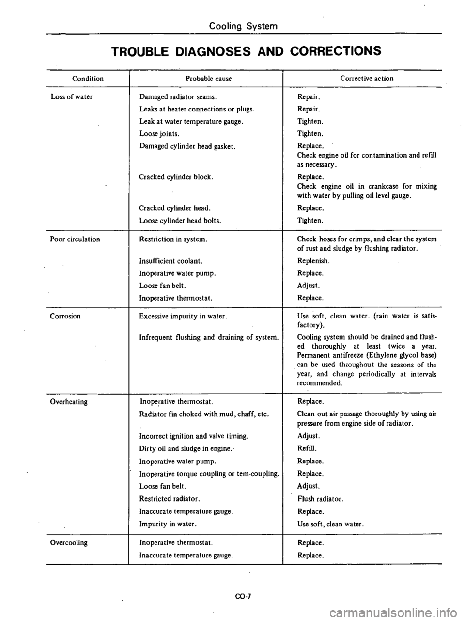
Condition
Loss
of
water
Poor
circulation
Corrosion
Overheating
Over
cooling
Cooling
System
TROUBLE
DIAGNOSES
AND
CORRECTIONS
Probable
cause
Damaged
radiator
seams
Leaks
at
heater
connections
or
plugs
Leak
at
water
temperature
gauge
Loose
joints
Damaged
cylinder
head
gasket
Cracked
cylinder
block
Cracked
cylinder
head
Loose
cylinder
head
bolts
Restriction
in
system
Insufficient
coolant
Inoperative
water
pump
Loose
fan
belt
Inoperative
thermostat
Excessive
impurity
in
water
Infrequent
flushing
and
draining
of
system
Inoperative
thermostat
Radiator
fin
choked
with
mud
chaff
etc
Incorrect
ignition
and
valve
timing
Dirty
oil
and
sludge
in
engine
Inoperative
water
pump
Inoperative
torque
coupling
or
tem
coupling
Loose
fan
belt
Restricted
radiator
Inaccurate
temperature
gauge
Impurity
in
water
Inoperative
thermostat
Inaccurate
temperature
gauge
CO
7
Corrective
action
Repair
Repair
Tighten
Tighten
Replace
Check
engine
oil
for
contamination
and
reml
as
necessary
Replace
Check
engine
oil
in
crankcase
for
mixing
with
water
by
pulling
oil
level
gauge
Replace
Tighten
Check
hoses
for
crimps
and
clear
the
system
of
rust
and
sludge
by
flushing
radiator
Replenish
Replace
Adjust
Replace
Use
soft
clean
water
rain
water
is
satis
factory
Cooling
system
should
be
drained
and
flush
ed
thoroughly
at
least
twice
a
year
Permanent
antifreeze
Ethylene
glycol
base
can
be
used
throughout
the
seasons
of
the
year
and
change
periodically
at
intervals
recommended
Replace
Clean
out
air
passage
thoroughly
by
using
air
pressure
from
engine
side
of
radiator
Adjust
Refill
Replace
Replace
Adjust
Flush
radiator
Replace
Use
soft
dean
water
Replace
Replace
Page 142 of 548
1l
I
I
1J
1
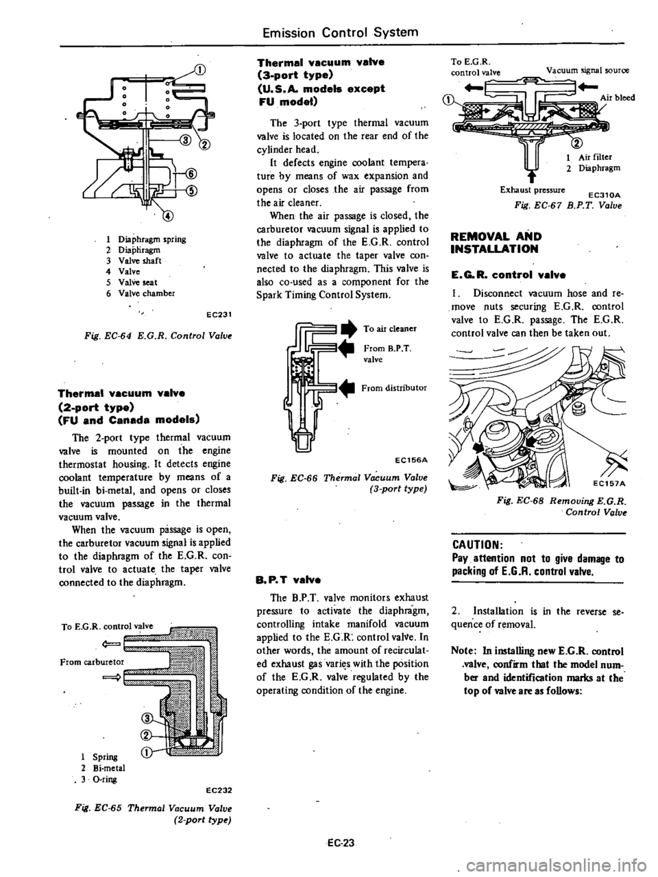
Diaphragm
spring
2
Diapliragm
3
Valve
shaft
4
Valve
5
ValVe
seat
6
Valve
chamber
EC231
Fig
EC
64
E
G
R
Control
Value
Thermal
vacuum
valve
2
port
type
FU
and
Canada
models
The
2
port
type
thermal
vacuum
valve
is
mounted
on
the
engine
thermostat
housing
It
detects
engine
coolant
temperature
by
means
of
a
built
in
bi
metal
and
opens
or
closes
the
vacuum
passage
in
the
thermal
vacuum
valve
When
the
vacuum
passage
is
open
the
carburetor
vacuum
signal
is
applied
to
the
diaphragm
of
the
E
G
R
con
trol
valve
to
actuate
the
taper
valve
connected
to
the
diaphragm
1
Spring
2
Bi
metal
3
O
ring
EC232
Fig
EC
65
Thermal
Vacuum
Valve
2
port
type
Emission
Control
System
Thermal
vacuum
valve
3
port
type
U
S
A
models
except
FU
model
The
3
port
type
thermal
vacuum
valve
is
located
on
the
rear
end
of
the
cylinder
head
It
defects
engine
coolant
tempera
ture
by
means
of
wax
expansion
and
opens
or
closes
the
air
passage
from
the
air
cleaner
When
the
air
passage
is
closed
the
carburetor
vacuum
signal
is
applied
to
the
diaphragm
of
the
E
G
R
control
valve
to
actuate
the
taper
valve
con
nected
to
the
diaphragm
This
valve
is
also
co
used
as
a
component
for
the
Spark
Timing
Control
System
JiI2
To
air
cleaner
From
B
P
T
valve
From
distributor
EC156A
Fig
EC
66
Thermal
Vacuum
Valve
3
port
type
B
P
T
valve
The
B
P
T
valve
monitors
exhaust
pressure
to
activate
the
diaphragm
controlling
intake
manifold
vacuum
applied
to
the
E
G
R
control
vaNe
In
other
words
the
amount
of
recirculat
ed
exhaust
gas
vari
s
with
the
position
of
the
E
G
R
valve
regulated
by
the
operating
condition
of
the
engine
EC
23
To
E
G
R
control
valve
Vacuum
nal
Curce
Air
bleed
1
Exhaust
pressure
EC310A
Fig
EC
67
B
P
T
Value
REMOVAL
AND
INSTALLATION
E
G
R
control
valve
I
Disconnect
vacuum
hose
and
re
move
nuts
securing
E
G
R
control
valve
to
E
G
R
passage
The
E
G
R
control
valve
can
then
be
taken
out
Fig
EC
68
Remouing
E
G
R
Control
Valve
CAUTION
Pay
attention
not
to
give
damage
to
packing
of
E
G
R
control
valve
2
Installation
is
in
the
reverse
se
quence
of
removal
Note
In
installing
new
E
G
R
control
valve
confirm
that
the
model
num
ber
and
identification
marks
at
the
top
of
valve
are
as
follows
Page 143 of 548
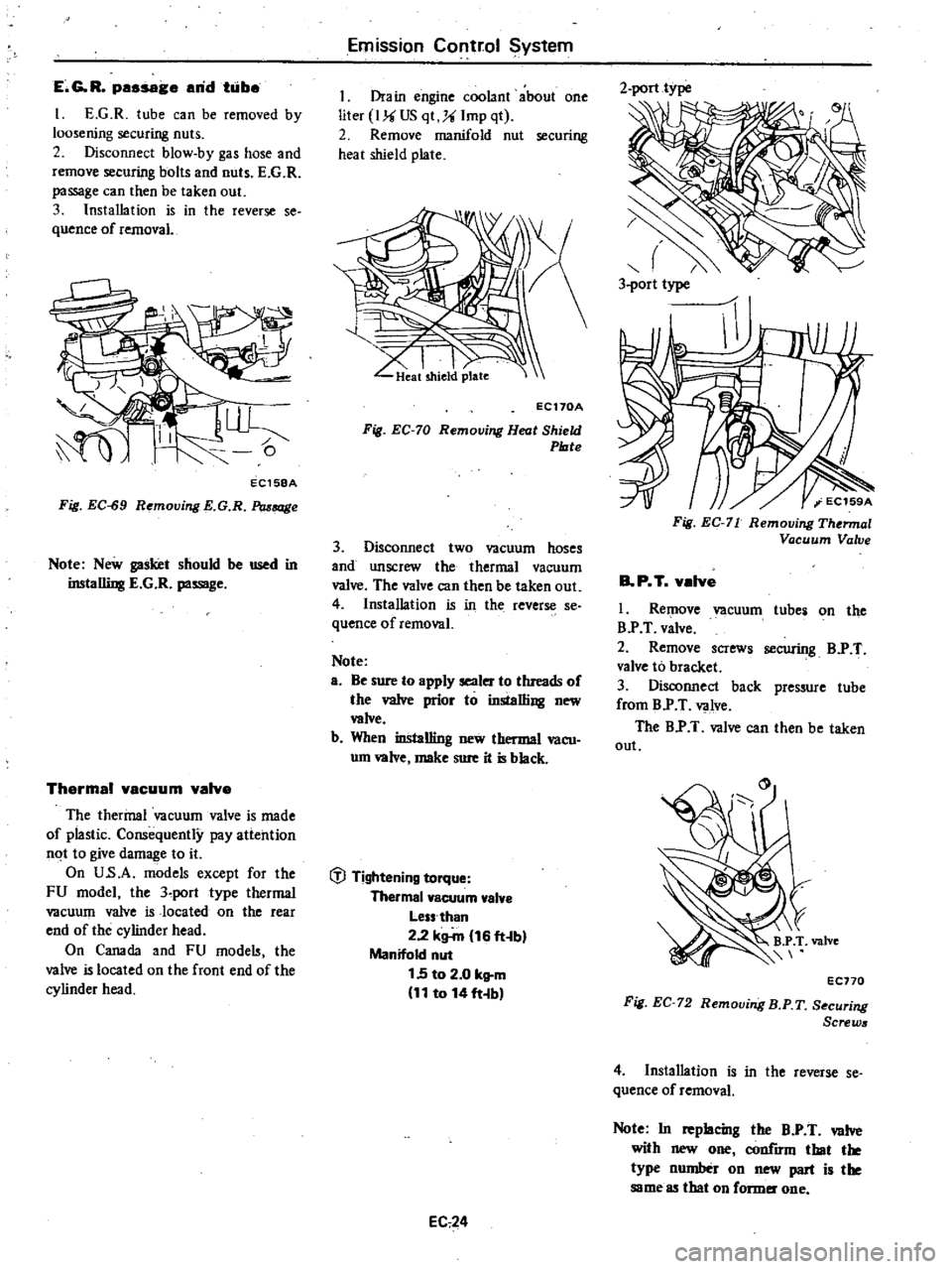
E
G
R
passage
arid
taibe
I
E
G
R
tube
can
be
removed
by
loosening
securing
nuts
2
Disconnect
blow
by
gas
hose
and
remove
securing
bolts
and
nuts
E
G
R
passage
can
then
be
taken
out
3
Installation
is
in
the
reverse
se
quence
of
removal
EC158A
Fig
EC
S9
Removing
E
G
R
Passage
Note
New
gasket
should
be
used
in
installing
E
G
R
passage
Thermal
vacuum
valve
The
thermal
vacuum
valve
is
made
of
plastic
Consequently
pay
attention
not
to
give
damage
to
it
On
U
s
A
models
except
for
the
FU
model
the
3
port
type
thermal
vacuum
valve
is
located
on
the
rear
end
of
the
cylinder
head
On
Canada
and
FU
mode
the
valve
is
located
on
the
front
end
of
the
cylinder
head
Emission
Corltr
ol
System
I
Drain
engine
coolant
about
one
liter
I
US
qt
Imp
qt
2
Remove
manifold
nut
securing
heat
shield
plate
I
I
LIkat
shield
plate
EC170A
Fig
EC
70
Removing
Heat
Shield
Plate
3
Disconnect
two
vacuum
hoses
and
unscrew
the
thermal
vacuum
valve
The
valve
can
then
be
taken
out
4
Installation
is
in
the
reverse
se
quence
of
removal
Note
a
Be
sure
to
apply
sealer
to
threads
of
the
valve
prior
to
installing
new
wive
b
When
installing
new
thermal
vacu
um
wive
make
sure
it
is
black
t
J
Tightening
torque
Thermal
vacuum
valve
Less
than
2
2
kg
m
16
ft
b
Manifold
nut
1
5
to
2
0
kg
m
11
to
14
ft
b
EC
24
2
port
type
3
port
type
Fig
EC
71
Removing
Thermal
Vacuum
Valve
B
P
T
valve
I
Remove
vacuum
tube
on
the
B
P
T
valve
2
Remove
screws
securing
B
P
T
valve
to
bracket
3
Disconnect
back
pressure
tube
from
B
P
T
valve
The
B
P
T
valve
can
then
be
taken
out
EC770
Fig
EC
72
Removing
B
P
T
S
curing
Screws
4
Installation
is
in
the
reverse
se
quence
of
removal
Note
In
replacing
the
B
P
T
valve
with
new
one
h
that
the
type
number
on
new
part
is
the
same
85
that
on
former
one
Page 144 of 548
INSPECTION
Entire
system
I
Make
a
thorough
vjsual
check
of
E
G
R
control
system
If
necessary
wipe
away
oil
to
facilitate
inspection
If
any
hoses
are
cracked
or
broken
replace
2
With
engine
stopped
inspect
E
G
R
control
valve
for
any
indication
of
binding
or
sticking
by
moving
dia
phragm
of
control
valve
upwards
with
a
finger
3
With
engine
running
inspect
E
G
R
control
valve
and
thermal
vacu
um
valve
for
normal
operation
1
When
engine
coolant
tempera
tun
is
low
Make
sure
that
E
G
R
control
valve
does
not
operate
when
engine
speed
is
increased
from
idling
to
3
000
to
3
500
rpm
Place
a
finger
on
the
diaphragm
of
E
G
R
control
valve
to
check
for
valve
operation
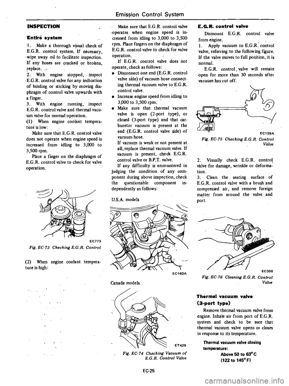
EC773
Fig
EC
73
Checking
E
G
R
Control
2
When
engine
coolant
tempera
tureishigh
Emission
Control
System
Make
sure
that
E
G
R
control
valve
operates
when
engine
speed
is
in
creased
from
idling
to
3
000
to
3
500
rpm
Place
fingers
on
the
diaphragm
of
E
G
R
control
valve
to
check
for
valve
operation
If
E
G
R
control
valve
does
not
operate
check
as
follows
Disconnect
one
end
E
G
R
control
valve
side
of
vacuum
hose
connect
ing
ihermal
vacuum
valve
to
E
G
R
control
valve
Increase
engine
speed
from
idling
to
3
000
to
3
500
rpm
Make
sure
that
thermal
vacuum
valve
is
open
2
port
type
or
closed
3
port
type
and
that
car
buretor
vacuum
is
present
at
the
end
E
G
R
control
valve
side
of
vacuum
hose
If
vacuum
is
weak
or
not
present
at
all
replace
thermal
vacuum
valve
If
vacuum
is
present
check
E
G
R
control
valve
or
B
P
T
valve
If
any
difficulty
is
encountered
in
judging
the
condition
of
any
com
ponent
during
above
inspection
check
the
questionable
component
in
dependently
as
follows
U
S
A
models
Ie
EC160A
Canada
models
ET429
Fig
EC
74
Checking
Vacuum
of
E
G
R
Control
Valve
EC
25
E
G
R
control
valve
Dismount
E
G
R
control
valve
from
engine
I
Apply
vacuum
to
E
G
R
control
valve
referring
to
the
following
figure
If
the
valve
moves
to
full
position
it
is
normal
E
G
R
control
valve
will
remain
open
for
more
than
30
seconds
after
vacuum
has
cut
off
5t
orr
rl
1
1
Fig
EC
75
EC129A
Checking
E
G
R
Control
Valve
2
Visually
check
E
G
R
control
wive
for
damage
wrinkle
or
deforma
tion
3
Clean
the
seating
surface
of
E
G
R
control
valve
with
a
brush
and
compressed
air
and
remove
foreign
matter
from
around
the
valve
and
port
Fig
EC
76
Cleoning
E
G
R
Control
Valve
Thermal
vacuum
valve
3
port
type
Remove
thermal
vacuum
valve
from
engine
Inhale
air
from
port
ofE
G
R
system
and
check
to
be
sure
that
thermal
vacuum
valve
opens
or
closes
in
response
to
its
temperature
Thermal
vacuum
valve
dosing
temperature
Above
50
to
630
C
122
to
1450
F