wheel size DATSUN 210 1979 Service Manual
[x] Cancel search | Manufacturer: DATSUN, Model Year: 1979, Model line: 210, Model: DATSUN 210 1979Pages: 548, PDF Size: 28.66 MB
Page 48 of 548

EM142
Fig
EM
48
Measuring
Bearing
Clearance
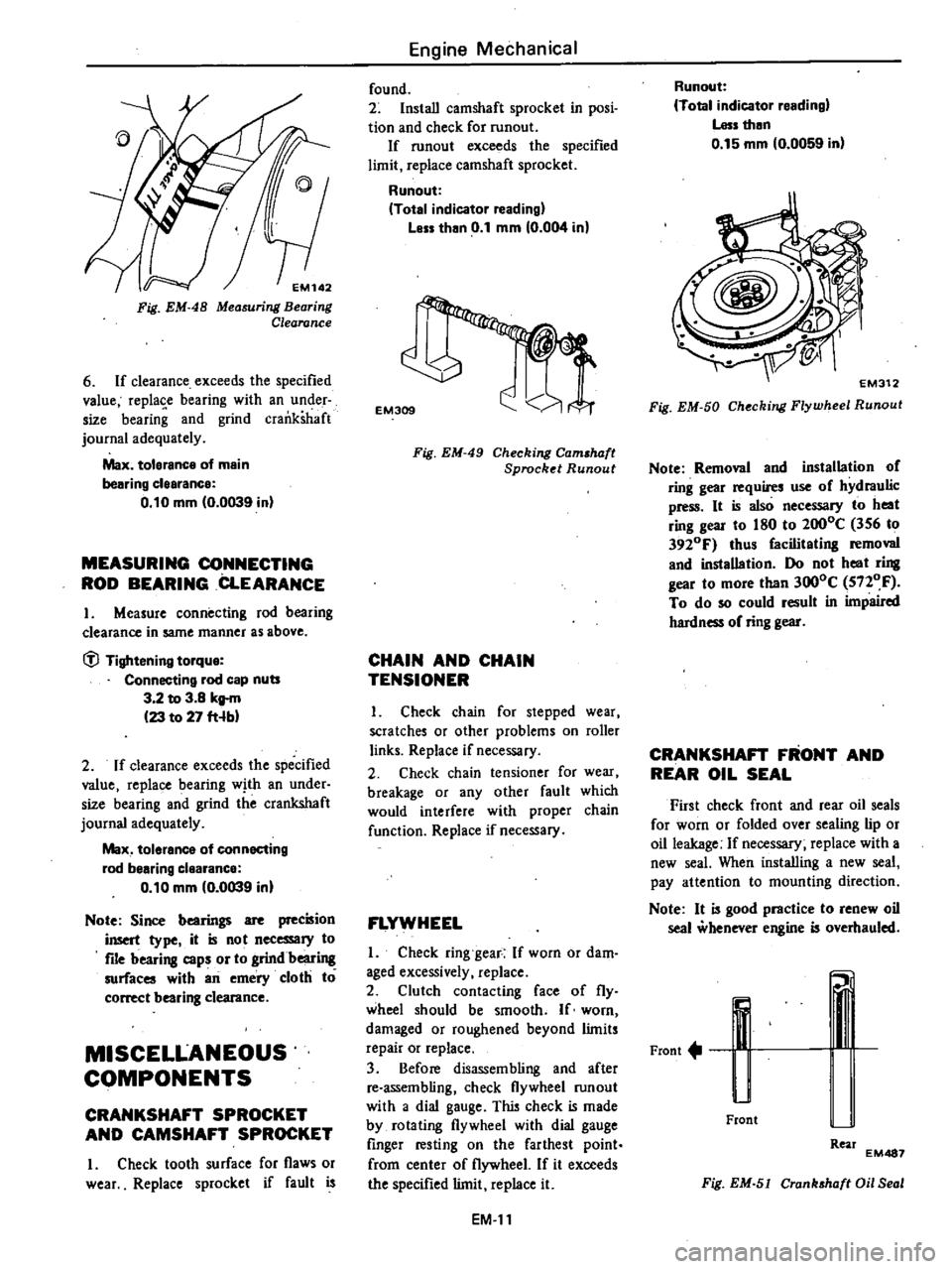
6
If
clearance
exceeds
the
specified
value
replase
bearing
with
an
under
size
bearing
and
grind
crankshaft
journal
adequately
Max
tolerance
of
main
bearing
clearance
0
10
mm
0
0039
in
MEASURING
CONNECTING
ROD
BEARING
CLEARANCE
I
Measure
connecting
rod
bearing
clearance
in
same
manner
as
above
tfl
Tightening
torque
Connecting
rod
cap
nuts
3
2
to
3
8
kg
m
23
to
27
fHb
2
If
clearance
exceeds
the
specified
value
replace
bearing
with
an
under
size
bearing
and
grind
the
crankshaft
journal
adequately
Max
tolerance
of
connecting
rod
bearing
clearance
0
10
mm
0
0039
in
Note
Since
bearings
are
precision
insert
type
it
is
not
necessary
to
file
bearing
caps
or
to
grindbeari
surfaces
with
an
emery
cloth
to
correct
bearing
clearance
MISCELLANEOUS
COMPONENTS
CRANKSHAFT
SPROCKET
AND
CAMSHAFT
SPROCKET
I
Check
tooth
surface
for
flaws
or
wear
Replace
sprocket
if
fault
is
Engine
Mechanical
found
2
Install
camshaft
sprocket
in
posi
tion
and
check
for
runout
If
runout
exceeds
the
specified
limit
replace
camshaft
sprocket
Runout
Total
indicator
reading
Less
than
0
1
mm
0
004
in
EM309
Fig
EM
49
Checking
Cam
haft
Sprocket
Runout
CHAIN
AND
CHAIN
TENSIONER
I
Check
chain
for
stepped
wear
scratches
or
other
problems
on
roller
links
Replace
if
necessary
2
Check
chain
tensioner
for
wear
breakage
or
any
other
fault
which
would
interfere
with
proper
chain
function
Replace
if
necessary
FLYWHEEL
I
Check
ring
gear
If
worn
or
dam
aged
excessively
replace
2
Clutch
contacting
face
of
fly
wheel
should
be
smooth
If
worn
damaged
or
roughened
beyond
limits
repair
or
replace
3
Before
disassembling
and
after
re
assembling
check
flywheel
run
out
with
a
dial
gauge
This
check
is
made
by
rotating
flywheel
with
dial
gauge
finger
resting
on
the
farthest
point
from
center
of
flywheel
If
it
exceeds
the
specified
limit
replace
it
EM
II
Runout
Total
indicator
reading
Less
then
0
15
mm
0
0059
in
Fig
EM
50
Checking
Flywheel
Runout
Note
Removal
and
installation
of
ring
gear
requires
use
of
hydraulic
press
It
is
also
necessary
to
heat
ring
gear
to
180
to
2000C
356
to
3920F
thus
facilitating
removal
and
installation
Do
not
heat
ring
gear
to
more
than
3000C
5nOF
To
do
so
could
result
in
impaired
hardness
of
ring
gear
CRANKSHAFT
FRONT
AND
REAR
OIL
SEAL
First
check
front
and
rear
oil
seals
for
worn
or
folded
over
sealing
lip
or
oil
leakage
If
necessary
replace
with
a
new
seal
When
installing
a
new
seal
pay
attention
to
mounting
direction
Note
It
is
good
practice
to
renew
oil
seal
whenever
engine
is
overhauled
Front
u
Front
Rear
EM487
Fig
EM
51
Cranhhaft
Oil
Seal
Page 66 of 548

Engine
Mechanical
Main
bearing
undersize
Unit
mm
in
Main
bearing
undersi
ze
Crank
journal
diameter
Standard
size
49
943
to
49
964
1
9663
to
1
9671
0
25
0
0098
49701
to
49
714
1
9567
to
1
9572
Undersize
0
50
0
0197
49451
to
49
464
1
9469
to
1
9474
0
75
0
0295
49
201
to
49
214
1
9370
to
1
9376
Connecting
rod
bearing
undersize
Unit
mm
in
Connecting
rod
bearing
undersize
Crank
pin
diameter
Standard
size
44
954
to
44
974
1
7698
to
I
7706
0
08
0
0031
44
881
to
44
894
1
7670
to
1
7675
0
25
0
0098
44
711
to
44
724
1
7603
to
1
7608
Undersize
0
50
0
0197
44
461
to
44
474
1
7504
to
1
7509
0
75
0
0295
44
211
to
44
224
1
7406
to
I
7411
MISCELLANEOUS
COMPONENTS
Unit
mm
in
Max
tolerance
Runout
of
camshaft
0
1
0
004
0
15
0
0059
Runout
of
flywheel
EM
29
Page 381 of 548

Wheel
and
Tire
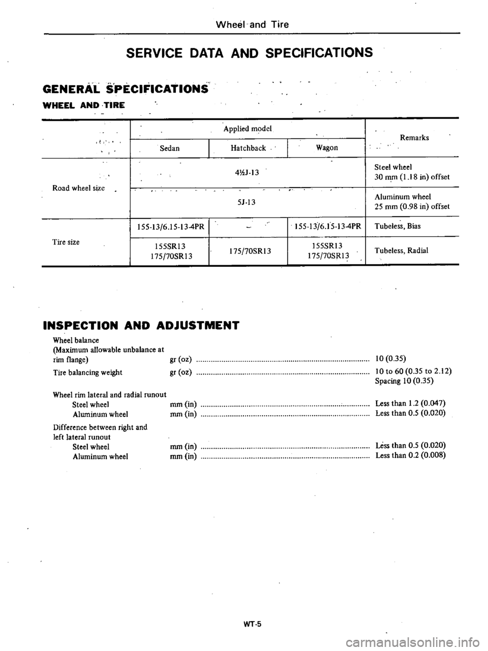
SERVICE
DATA
AND
SPECIFICATIONS
GENERAL
SPECIFICATIONS
WHEEL
AND
TIRE
Road
wheel
size
Applied
m
del
Remarks
Sedan
Hatchback
Wagon
4
OJ
13
Steel
wheel
30
mm
I
I
8
in
offset
5J
13
Aluminum
wheel
25
mm
0
98
in
offset
155
13
6
1
5
13
4PR
155
13
6
1
5
13
4PR
Tubeless
Bias
l55SRl3
l75
70SR13
155SRl3
Tubeless
Radial
l75
70SR13
l75
70SR13
Tire
size
INSPECTION
AND
ADJUSTMENT
Wheel
balance
Maxilnum
allowable
unbalance
at
riln
flange
Tire
balancing
weight
gr
oz
gr
oz
10
0
35
10
to
60
0
35
to
2
12
Spacing
10
0
35
Wheel
riln
lateral
and
radial
runout
Steel
wheel
mm
in
Aluminum
wheel
mm
in
Difference
between
right
and
left
lateral
runout
Steel
wheel
Aluminum
wheel
Less
than
1
2
0
047
Less
than
0
5
0
020
mm
in
mm
in
Less
than
0
5
0
020
Less
than
0
2
0
008
WT5
Page 382 of 548

Wheel
and
Tire
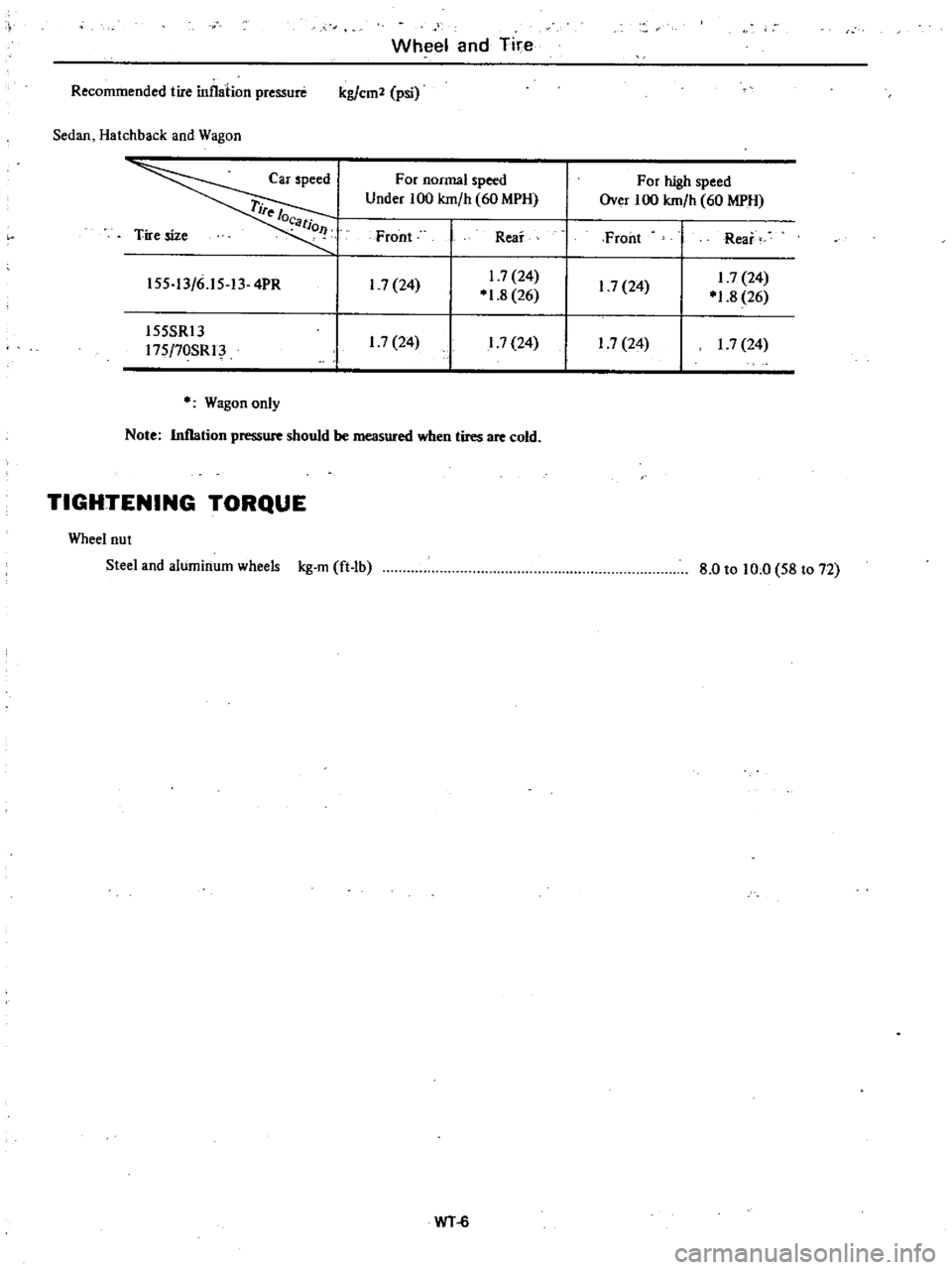
Recommended
tire
inflation
pressure
kg
em
psi
Sedan
Hatchback
and
Wagon
Tire
size
Car
speed
rife
l
o
tio
l
For
normal
speed
For
high
speed
Under
100
km
h
60
MPH
Over
100
km
h
60
MPH
Front
Rear
Front
Rear
I
7
24
1
7
24
1
7
24
1
7
24
01
8
26
01
8
26
17
24
1
7
24
1
7
24
17
24
155
13
6
15
13
4PR
155SRl3
175
70SRI
o
Wagon
only
Note
Inflation
pressure
should
be
measured
when
tires
are
cold
TIGHTENING
TORQUE
Wheel
nut
Steel
and
aluminum
wheels
kg
m
ft
lb
8
0
to
10
0
58
to
72
WT
6