heater DATSUN 210 1979 Service Manual
[x] Cancel search | Manufacturer: DATSUN, Model Year: 1979, Model line: 210, Model: DATSUN 210 1979Pages: 548, PDF Size: 28.66 MB
Page 9 of 548
Erigine
crankcase
EI
gine
cooling
system
Transmission
case
Final
drive
case
housing
Steering
gear
box
Fuel
tank
Air
conditioning
system
Refrigerant
Compressor
oil
f
tl
It
J
4
i
1
protect
the
catalytic
cop
verter
froitr
contamination
t
n
General
Information
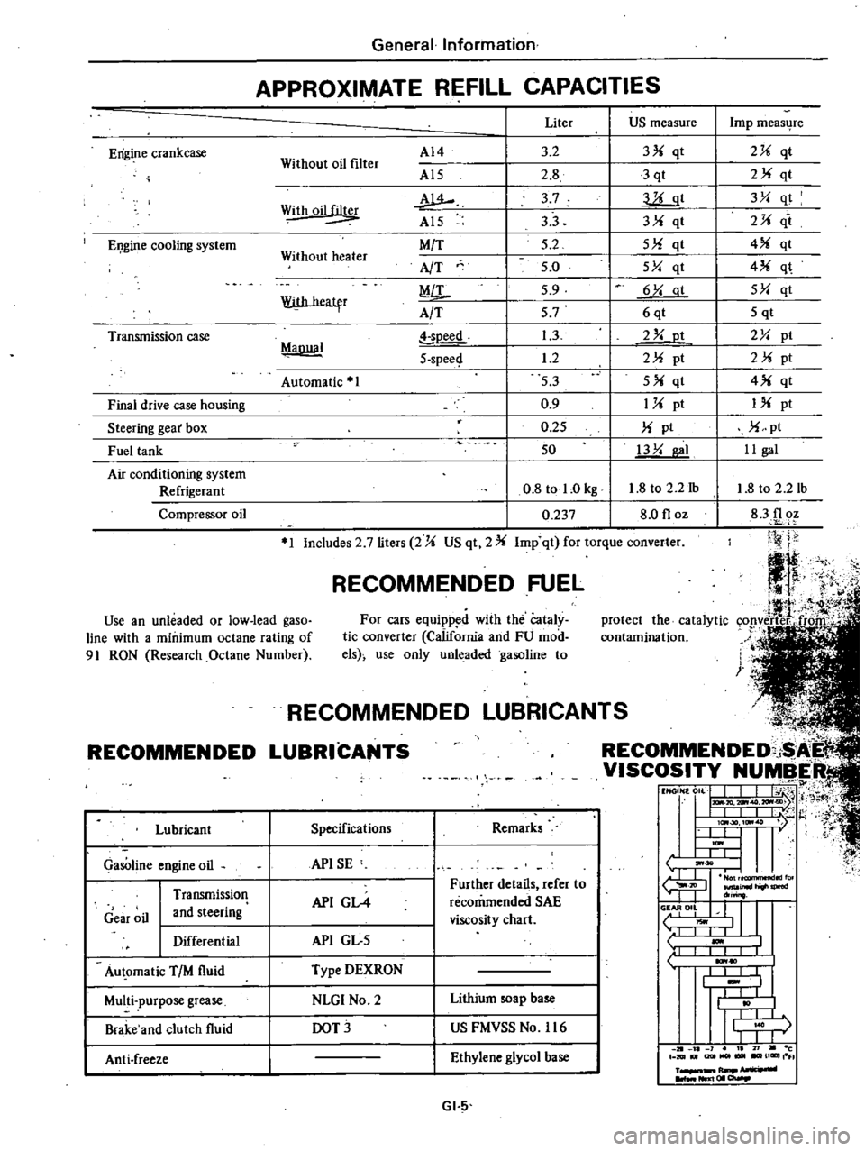
APPROXIMATE
REFILL
CAPACITIES
Without
oil
filter
AI4
Al5
w
Al5
M
T
AfT
MiL
A
T
Liter
US
measure
3
2
3
qt
2
8
3
qt
3
7
llLgt
33
3
qt
5
2
5
qt
5
0
5Y
qt
5
9
6
Y
at
57
6qt
1
3
2
Y
ot
1
2
2
pt
53
5
qt
0
9
1
pt
0
25
pt
50
13
Y
I
0
8
tol
Okg
1
8
to
2
2
1b
0
237
8
0
floz
Withoil
Without
heater
With
heatfr
MaDllal
soeed
5
spee
Automatic
1
1
Includes
2
7
liters
2
US
qt
2
Imp
qt
for
torque
converter
RECOMMENDED
FUEL
Use
an
unleaded
or
low
lead
gaso
line
with
a
minimum
octane
rating
of
91
RON
Research
Octane
Number
For
cars
equipp
d
with
the
Cataly
tic
converter
California
and
FU
mod
els
use
only
unleaded
gasoline
to
RECOMMENDED
Lubricant
GasOline
engine
oil
Gear
oil
Transmission
and
steering
Differential
Au
omatic
TIM
fluid
Multi
purpose
grease
Brake
and
clutch
fluid
Anti
freeze
L
NDED
LUBRICAN
COMMENDED
i
I
VISCOSITY
NUMBER
t1
NGON
0
L
J
I
j
H
I
IlL
I
t
l
I
lc
30
ItM
7
l
t
U
I
ItM
I
L
L
tJ
30
I
I
fu
JIl
inld
do
o
II
L
liOwl
1
I
I
1
10
I
I
I
I
t
I
I
j
r
I
I
J
1
21
l
1
I
71
c
DIUt
I2lItMOl
UGIIII
FI
R
NIl
I
01
a
Specifications
Remarks
APISE
API
GL4
Further
details
refer
to
recommended
SAE
viscosity
chart
API
GL
5
Type
DEXRON
NLGI
No
2
Lithium
soap
base
DOT
US
FMVSS
No
116
Ethylene
glycol
base
GI
5
Imp
meas4re
2
qt
2
qt
3Y
qt
2
it
4
qt
4
q
5Y
qt
5
qt
2Y
pt
2
pt
4
qt
I
pt
pt
II
gal
1
8
to
2
2
lb
83f1
oz
Ji
j
j
Page 18 of 548
pl
ice
mter
as
an
assembly
2
When
installing
oil
mter
tighten
by
hand
Note
Do
not
overtighten
oil
filter
lest
leakage
shoUld
occur
CHANGING
ENGINE
COOLANT
PERMANENT
ANTI
FREEZE
COOLANT
Note
The
permanent
anti
freeze
coolant
is
an
ethylene
glya
l
base
product
containing
chemical
in
hibitors
to
protect
the
cooling
system
from
rusting
and
corrosion
The
anti
freeze
does
not
cOntain
any
glycerine
or
ethyl
alcohol
It
will
not
evaporate
or
boil
a
ay
and
can
be
ilsed
with
either
high
or
low
temperature
thermostats
It
flows
freely
transfers
heat
efficiently
and
will
not
clog
the
passages
in
the
cooling
system
The
anti
freeze
must
not
be
mixed
with
other
product
This
coolant
can
be
used
throughout
the
seasons
of
the
year
Whenever
coolant
is
changed
the
cooling
system
must
be
flushed
and
refilled
with
a
new
coolant
Check
the
coolant
level
See
instructions
attached
to
the
anti
freeze
container
for
mixing
ratio
of
anti
freeze
to
water
CHECKING
COOLING
SYSTEM
HOSES
AND
CONNECTIONS
Check
hoses
and
fittings
for
loose
connections
or
deterioration
Re
tighten
or
replace
if
necessary
INSPECTION
OF
RADIATOR
CAP
Apply
reference
pressure
0
9
kgj
cm2
13
psi
to
radiator
cap
by
means
of
a
cap
tester
to
see
if
it
is
satisfactory
Replace
cap
assembly
if
necessary
I
j
ngine
Tune
up
ET012
Fig
ET
3
Testing
Radiator
Cap
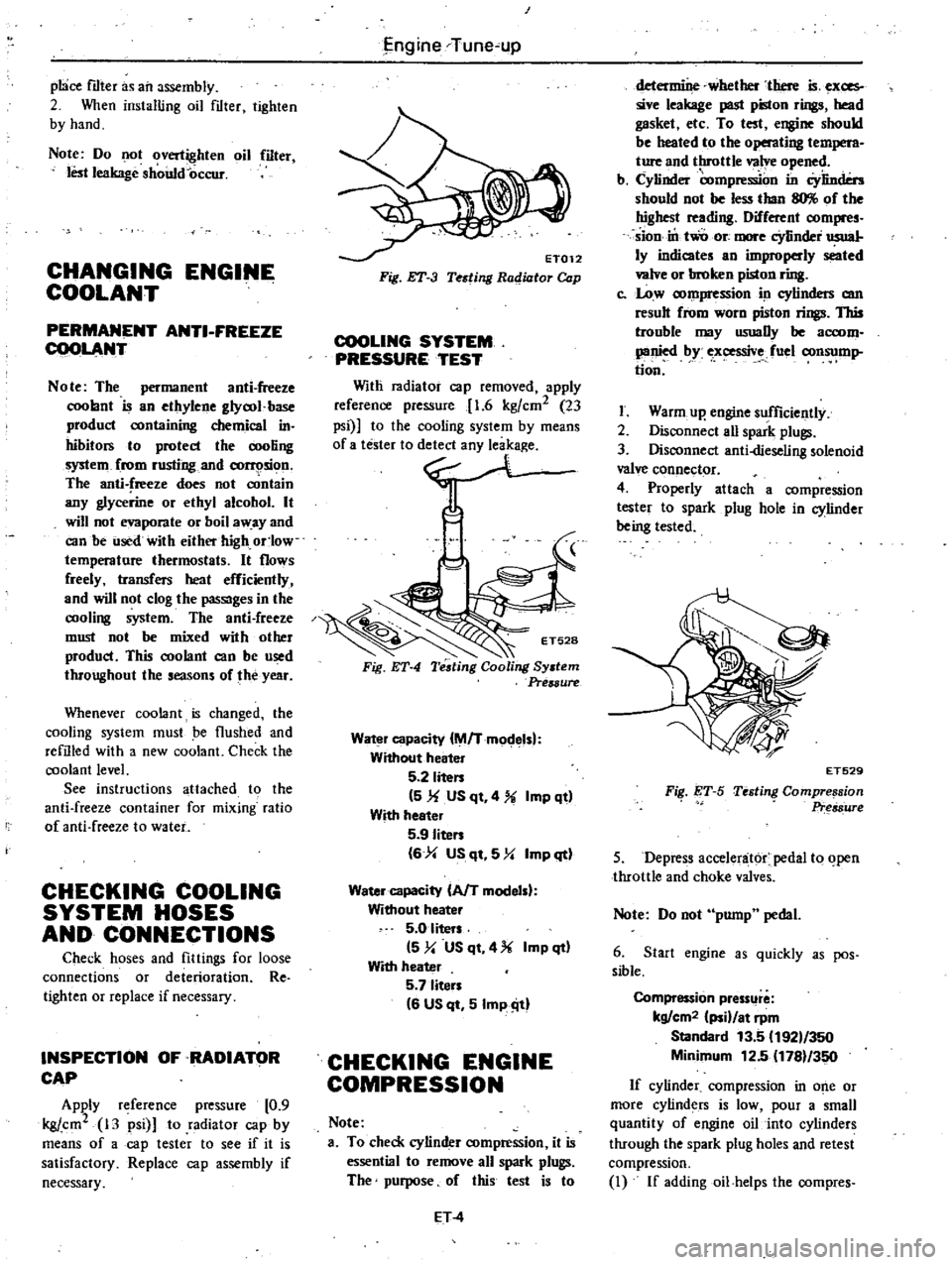
COOLING
SYSTEM
PRESSURE
TEST
Witli
radiator
cap
removed
apply
reference
pressure
1
6
kgfcm2
23
psi
to
the
cooling
system
by
means
0
no
Fig
ET
4
Water
capacity
M
Tmodelsl
Without
heater
5
2
liten
5
1f
US
qt
4
Imp
qt
With
heeter
5
9
Iiten
6
4
US
qt
5
Y
Imp
qt
Water
capacity
AfT
modelsl
Without
heater
5
0
liters
5
y
US
qt
4
Imp
qt
With
heater
5
7
liten
6
US
qt
5
Imp
ill
CHECKING
ENGINE
COMPRESSION
Note
a
To
check
cylinder
compression
it
is
essential
to
remove
all
spark
plugs
The
purpose
of
this
test
is
to
ET
4
determine
whether
there
is
exces
sive
leakage
past
piston
rings
head
gasket
etc
To
test
engine
should
be
heated
to
the
operating
t
M
ture
and
throttle
valve
opened
b
Cylinder
compre
on
in
Cylinders
should
not
be
less
than
llO
of
the
highest
reading
Different
compres
sion
in
two
ore
more
cYlinder
usual
ly
indicates
an
improperly
seated
valve
or
broken
piston
ring
c
Low
compression
in
cylinders
am
result
from
worn
piston
rings
This
trouble
may
usuaDy
be
accom
panied
by
ex
ssive
fuel
consump
tion
I
Warm
up
engine
sufficiently
2
Disconnect
aU
spark
plugs
3
Disconnect
anti
dieseling
solenoid
valve
connector
4
Properly
attach
a
compression
tester
to
spark
plug
hole
in
cylinder
being
tested
FiI
ET
S
ET529
Testing
Compre
sion
Pr
s8ure
5
Depress
accelenit6r
pedal
to
open
throttle
and
choke
valves
Note
Do
not
pump
pedal
6
Start
engine
as
quickly
as
pos
sible
Compression
pressllre
kg
cm2
ii
at
rpm
Standard
13
5
192
350
Minimum
12
5
1781
350
If
cylinder
compression
in
o
e
or
more
cylinders
is
low
pour
a
small
quantity
of
engine
oil
into
cylinders
through
the
spark
plug
holes
and
retest
compression
I
If
addingoil
helps
the
compres
Page 28 of 548
Engine
T
une
up
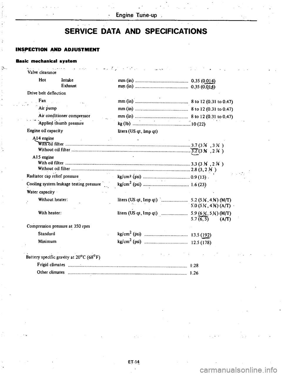
SERVICE
DATA
AND
SPECIFICATIONS
INSpECTION
AND
ADJUSTMENT
Basic
mechanical
s
stem
Valve
clearance
Hot
Intake
Exhaust
Drive
belt
deflection
Fan
Air
pump
Air
COo9itioner
compressor
Applied
thumb
pressure
Engine
oil
capacity
AI4
engine
wmi
oil
filter
Without
oil
filter
A
15
engine
With
oil
fIlter
Without
oil
filter
Radiator
cap
relief
pressure
Cooling
system
leakage
testing
pressure
Water
capacity
Without
heater
With
heater
Compression
pressure
at
350
rpm
Standard
Minimum
Battery
specific
gravity
at
200C
680F
Frigid
climates
Other
climates
mm
in
mm
in
0
35
0
014
0
5
O
QI
i
mm
in
mm
in
mm
in
kg
lb
liters
US
qt
lmp
qt
8
to
12
0
31
to
0
47
8
to
12
0
31
to
0
47
8
to
12
0
31
to
0
47
10
22
37
3Ji
3
Y
IT
3
2Ji
kgfcm2
psi
kg
cm2
psi
33
3
Ji
2
Ji
2
8
3
2
f
0
9
13
1
6
23
liters
US
qt
lmp
qt
5
2
5
f
4
MfT
5
0
5Y
4
AfT
5
9
6Y
5
MfT
57
6
5
AfT
liters
US
qt
lmp
qt
kgfcm2
psi
kgfcm2
psi
13
5
192
12
5
178
1
28
1
26
ET11
Page 80 of 548
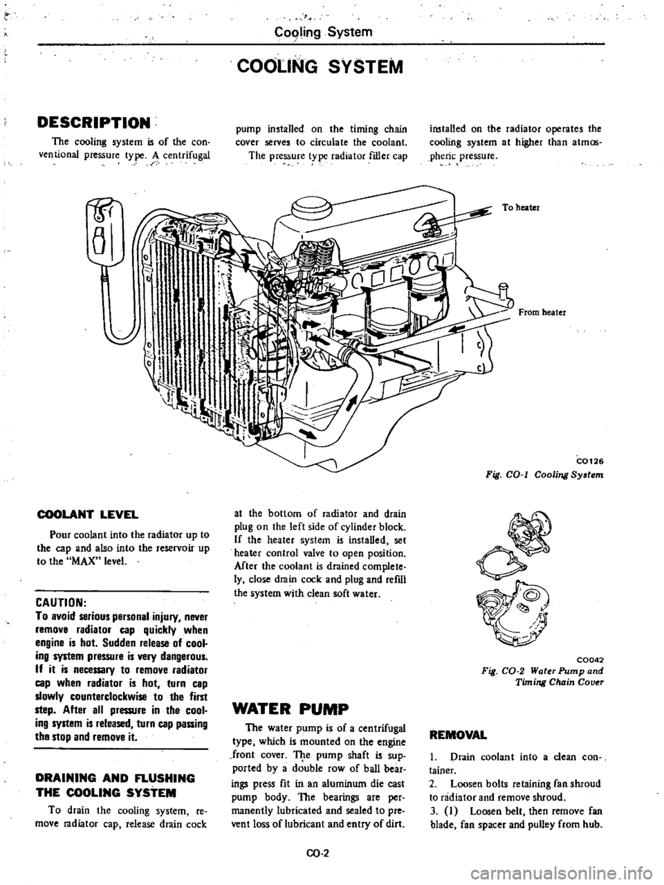
DESCRIPTION
The
cooling
system
is
of
the
con
ventional
pressure
type
A
centrifugal
1P
a
COOLANT
LEVEL
Pour
coolant
into
the
radiator
up
to
the
cap
and
also
into
the
reservoir
up
to
the
MAX
level
CAUTION
To
avoid
serious
personal
injury
never
remove
radiator
cap
quickly
when
engine
is
hot
Sudden
release
of
cool
ing
system
pressure
is
very
dangerous
If
it
is
necessary
to
remove
radiator
cap
when
radiator
is
hot
turn
cap
slowly
counterclockwise
to
the
first
step
After
all
pressure
in
the
cool
ing
system
is
released
turn
cap
passing
the
stop
and
remove
it
DRAINING
AND
FLUSHING
THE
COOLING
SYSTEM
To
drain
the
cooling
system
re
move
radiator
cap
release
drain
cock
C09ling
System
COOLING
SYSTEM
pump
installed
on
the
timing
chain
cover
serves
to
circulate
the
coolant
The
pressure
t
pe
radiator
filler
cap
at
the
bottom
of
radiator
and
drain
plug
on
the
left
side
of
cylinder
block
If
the
heater
system
is
instaDed
set
heater
control
valve
to
open
position
Mter
the
coolant
is
drained
complete
ly
close
drain
cock
and
plug
and
refdl
the
system
with
clean
soft
water
WATER
PUMP
The
water
pump
is
of
a
centrifugal
type
which
is
mounted
on
the
engine
front
cover
TJ
te
pump
shaft
is
sup
ported
by
a
double
row
of
baD
bear
ings
press
fit
in
an
aluminum
die
cast
pump
body
The
bearings
are
per
manently
lubricated
and
sealed
to
pre
vent
loss
of
lubricant
and
entry
of
dirt
CO
2
installed
on
the
radiator
operates
the
cooling
system
at
higher
than
atmos
pheric
pressure
To
heater
From
heater
C0126
Fig
COol
Cooling
System
C0042
Fig
CO
2
Water
Pump
and
Timing
Chain
Couer
REMOVAL
1
Drain
coolant
into
a
clean
con
tainer
2
Loosen
bolts
retaining
fan
shroud
to
radiator
and
remove
shroud
3
I
Loosen
belt
then
remove
fan
blade
fan
spacer
and
pulley
from
hub
Page 85 of 548
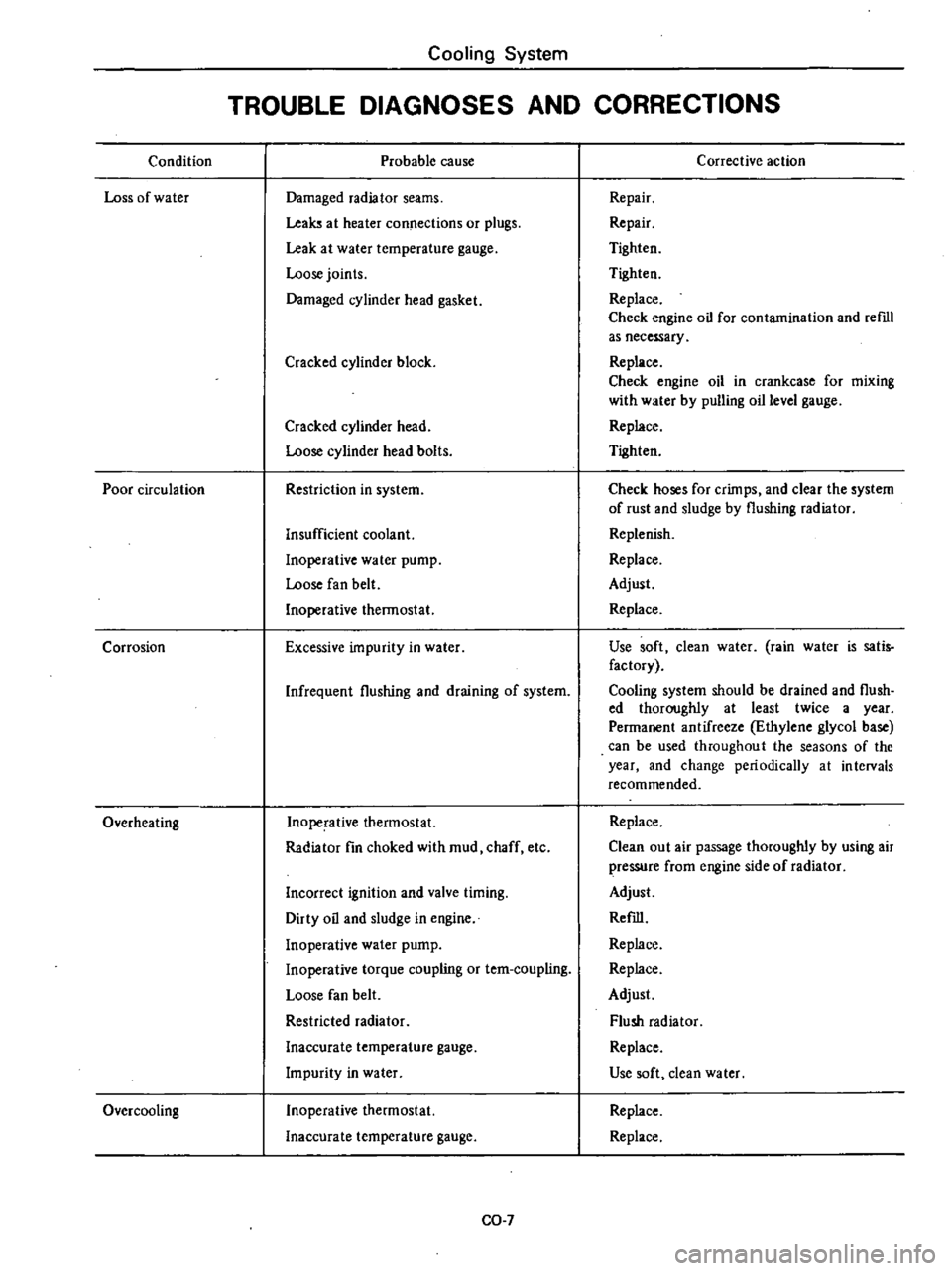
Condition
Loss
of
water
Poor
circulation
Corrosion
Overheating
Over
cooling
Cooling
System
TROUBLE
DIAGNOSES
AND
CORRECTIONS
Probable
cause
Damaged
radiator
seams
Leaks
at
heater
connections
or
plugs
Leak
at
water
temperature
gauge
Loose
joints
Damaged
cylinder
head
gasket
Cracked
cylinder
block
Cracked
cylinder
head
Loose
cylinder
head
bolts
Restriction
in
system
Insufficient
coolant
Inoperative
water
pump
Loose
fan
belt
Inoperative
thermostat
Excessive
impurity
in
water
Infrequent
flushing
and
draining
of
system
Inoperative
thermostat
Radiator
fin
choked
with
mud
chaff
etc
Incorrect
ignition
and
valve
timing
Dirty
oil
and
sludge
in
engine
Inoperative
water
pump
Inoperative
torque
coupling
or
tem
coupling
Loose
fan
belt
Restricted
radiator
Inaccurate
temperature
gauge
Impurity
in
water
Inoperative
thermostat
Inaccurate
temperature
gauge
CO
7
Corrective
action
Repair
Repair
Tighten
Tighten
Replace
Check
engine
oil
for
contamination
and
reml
as
necessary
Replace
Check
engine
oil
in
crankcase
for
mixing
with
water
by
pulling
oil
level
gauge
Replace
Tighten
Check
hoses
for
crimps
and
clear
the
system
of
rust
and
sludge
by
flushing
radiator
Replenish
Replace
Adjust
Replace
Use
soft
clean
water
rain
water
is
satis
factory
Cooling
system
should
be
drained
and
flush
ed
thoroughly
at
least
twice
a
year
Permanent
antifreeze
Ethylene
glycol
base
can
be
used
throughout
the
seasons
of
the
year
and
change
periodically
at
intervals
recommended
Replace
Clean
out
air
passage
thoroughly
by
using
air
pressure
from
engine
side
of
radiator
Adjust
Refill
Replace
Replace
Adjust
Flush
radiator
Replace
Use
soft
dean
water
Replace
Replace
Page 98 of 548
ELECTRIC
AUTOMATIC
CHOKE
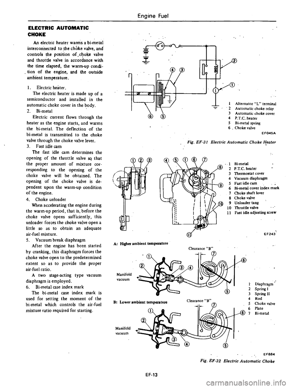
An
electric
heater
warms
a
bi
metal
interconnected
to
the
choke
valve
and
controls
the
position
of
c
oke
valve
and
throttle
valve
in
accordance
with
the
time
elapsed
the
warm
up
condi
tion
of
the
engine
and
the
outside
ambient
temperature
Electric
heater
The
electric
heater
is
made
up
of
a
semiconductor
and
installed
in
the
automatic
choke
cover
in
the
body
2
Bi
metal
Electric
current
flows
through
the
heater
as
the
engine
starts
and
warms
the
bi
metal
The
deflection
of
the
bi
metal
is
transmitted
to
the
choke
valve
through
the
choke
valve
lever
3
Fast
idle
cam
The
fast
idle
cam
determines
the
opening
of
the
throttle
valve
SQ
that
the
proper
amount
of
mixture
cor
responding
to
the
opening
of
the
choke
valve
will
be
obtained
The
opening
of
the
choke
valve
is
de
pendent
upon
the
warm
up
condition
of
the
engine
4
Choke
unloader
When
accelerating
the
engine
during
the
warm
up
period
that
is
before
the
choke
valve
opens
sufficiently
this
unloader
forces
the
choke
valve
open
a
little
so
as
to
obtain
an
adequate
air
fuel
mixture
S
Vacuum
break
diaphragm
After
the
engine
has
been
started
by
cranking
this
diaphragm
forces
the
choke
valve
open
to
the
predetermined
extent
so
as
to
provide
the
proper
air
fuel
ratio
A
two
stage
acting
type
vacuum
diaphragm
is
employed
6
Si
metal
case
index
mark
The
bi
metal
case
index
mark
is
used
for
selling
the
moment
of
the
bi
metal
which
controls
the
air
fuel
mixture
ratio
required
for
starting
Engine
Fuel
r
m
2
3
4
5
6
r
3
1
@
@
Alternator
L
terminal
Automatic
choke
relay
Automatic
choke
cover
P
T
C
heater
Bi
metaJ
spring
Choke
valve
Fig
EF
31
Electric
Automatic
Choke
l
eater
EF045A
l
A
Higher
ambient
temperature
Manifold
vacuum
Clearance
B
B
Lower
ambient
temperature
Clearance
Manifold
vacuum
1
Hi
metal
2
P
T
e
heater
3
Thermostat
cover
4
Vacuum
diaphragm
5
Fast
idle
earn
6
Bi
metal
cover
index
mark
7
Choke
shaft
lever
8
Choke
valve
9
Unloader
tang
10
Throttle
valve
11
Fast
idle
adjusting
screw
EF243
t
Diaphragm
2
Spring
I
3
Spring
11
4
Rod
5
Choke
valve
6
Plate
@
7
Bi
metal
EF884
Fig
EF
32
Electric
Automatic
Choke
EF
13
Page 101 of 548
CHOKEUNLOADER
I
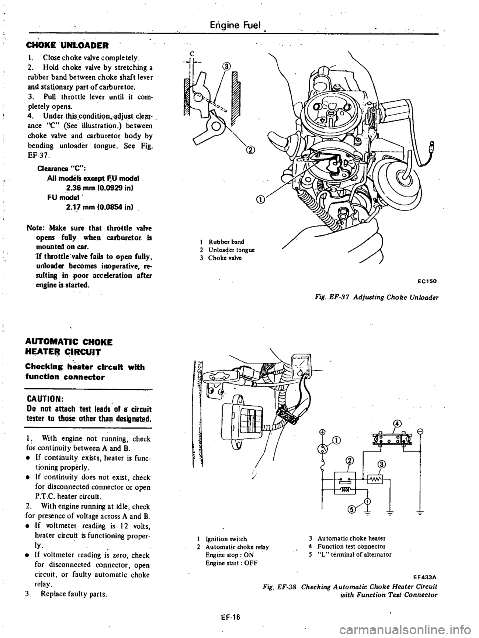
Close
choke
valve
completely
2
Hold
choke
valve
by
stretching
a
rubber
band
between
choke
shaft
lever
and
stationary
part
of
carllUretor
3
Pull
throttle
lever
until
it
com
pletely
opens
4
Under
this
condition
adjust
clear
ance
e
See
illustration
between
choke
valve
and
carburetor
body
by
bending
unloader
tongue
See
Fig
EF
37
Clearance
C
All
modelS
ex
pt
F
U
model
2
36
mm
0
0929
in
FU
model
2
17
mm
0
0854
in
Note
Make
sure
that
throttle
valve
opensfuDy
when
carburetor
is
mounted
on
car
If
throttle
valve
fails
to
open
fully
unloader
becomes
inoperative
re
suiting
in
poor
acceleration
after
engine
is
started
AUTOMATIC
CHOKE
HEATE
IRCUIT
Checking
heater
circuit
with
function
connector
CAUTION
00
not
attach
test
leads
of
8
circuit
tester
to
those
other
than
designated
I
With
engine
not
running
check
for
continuity
between
A
and
B
If
continuity
exists
heater
is
fune
tioning
properly
If
continuity
does
not
exist
check
for
discon
nected
connector
or
open
P
T
C
heater
circuit
2
With
engine
running
at
idle
check
for
presence
of
voltage
across
A
and
B
If
voltmeter
reading
is
12
volts
heater
circuit
is
functioning
proper
ly
If
voltmeter
reading
is
zero
check
for
disconnected
connector
open
circuit
or
faulty
automatic
choke
relay
3
Replace
faulty
parts
Engine
Fuel
c
i
CD
1
Rubber
band
2
Unloa
er
tongue
3
Choke
vaJve
f
rC
EC150
Fig
EF
37
Adjusting
Choke
Unloader
SJ
v
1
Ignition
switch
2
Automatic
choke
relay
Engine
stop
ON
Engine
start
OFF
3
Automatic
choke
heater
4
Function
test
connector
5
L
terminal
of
alternator
EF
16
Fig
EF
38
EF433A
Checking
Automatic
Choke
Heater
Circuit
with
Function
Teat
Connector
Page 102 of 548
AUTOMATIC
CHOKE
MECHANISM
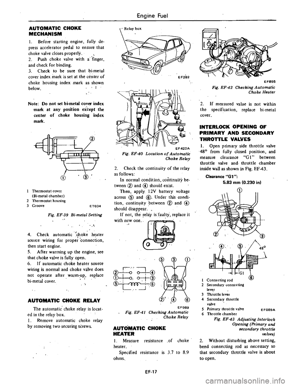
I
Before
starting
engine
fully
de
press
accelerator
pedal
to
ensure
that
choke
valve
closes
properly
2
Push
choke
valve
wi
th
a
finger
and
check
for
binding
3
Check
to
be
sure
that
bi
metal
cover
index
mark
is
set
at
the
center
of
choke
housing
index
mark
as
shown
below
I
Note
Do
not
set
b
metal
cover
index
mark
at
any
position
except
the
center
of
choke
housing
index
mark
CD
@
Thermosta
t
covel
Bi
metal
chamber
2
Thermostat
housing
3
Groove
E
T034
Fig
EF
39
Bi
metal
Setting
4
Check
automatic
choke
heater
source
wiring
for
proper
connection
then
start
engine
S
After
warming
up
the
engine
see
that
choke
valve
is
fully
open
6
If
automatic
choke
heater
source
wiring
is
normal
and
choke
valve
does
not
operate
after
warm
up
replace
bi
metal
cover
AUTOMATIC
CHOKE
RELAY
The
automatic
choke
relay
is
local
ed
in
the
relay
box
I
Remove
automatic
choke
relay
by
removing
two
securing
screws
Engine
Fuel
II
EF422A
Fig
EF
40
Location
of
Automatic
Choke
Relay
2
Check
the
continuity
of
the
relay
as
follows
In
normal
condition
continuity
be
tween
CV
and
@
should
exist
Then
apply
l2V
battery
voltage
across
CID
and
@
Under
this
condi
tion
contin
ity
between
CV
and
@
should
disappear
If
not
the
relay
is
faulty
replace
it
W
hWO
CID
CD
CV
o
0
@
Q
I
o
r
@
CID
@
EF989
Fig
EF
41
Checking
Automatic
Choke
Relay
AUTOMATIC
CHOKE
HEATER
I
Measure
resistance
of
choke
heater
Specified
resistance
is
3
7
to
8
9
ohms
EF
17
EF855
Fig
EF
42
Checking
Automatic
Choke
Heater
2
If
measured
value
is
not
within
the
specification
replace
bi
metal
cover
INTERLOCK
OPENING
OF
PRIMARY
AND
SECONDARY
THROTTLE
VALVES
1
Open
primary
side
throttle
valve
480
from
fully
closed
position
and
measure
clearance
G
1
between
throttle
valve
and
throttle
chamber
inside
wall
as
shown
in
Fig
EF
43
Clearance
6G1
5
83
mm
0
230
in
@
J
3
480
r
mit
GI
6
1
Connecting
rod
2
Secondary
connecting
lever
3
Throttle
lever
4
Secondary
throttle
valve
5
Primary
throttle
valve
6
Throttle
chamber
Fig
EF
43
Adjusting
Interlock
Opening
Primary
and
lecondary
throttle
values
2
Without
disturbing
above
setting
bend
connecting
rod
as
necessary
so
that
secondary
throttle
valve
is
about
to
open
E
F089A
Page 121 of 548
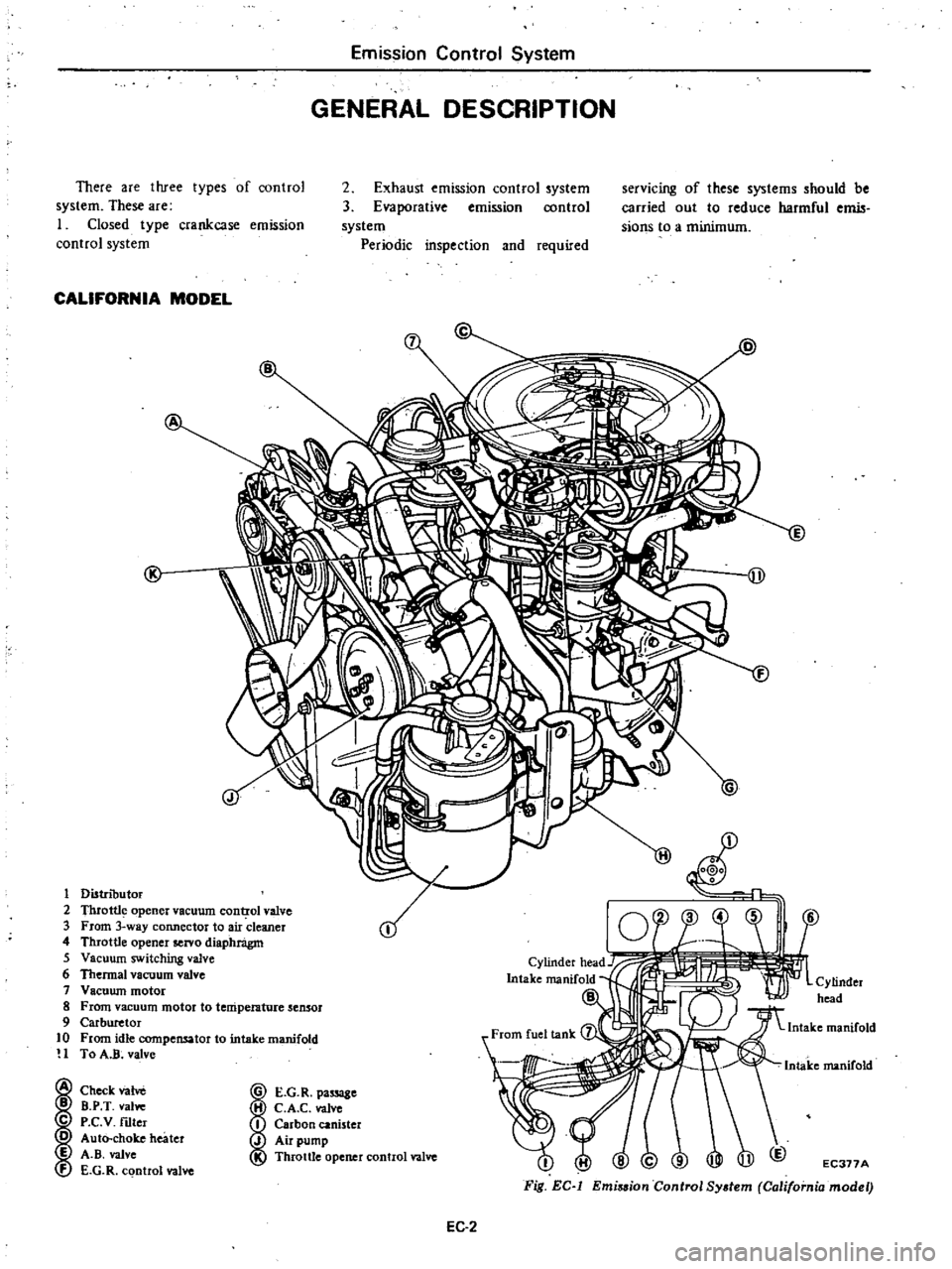
Emission
Control
System
GENERAL
DESCRIPTION
There
are
three
types
of
control
system
These
are
I
Closed
type
crankcase
emission
control
system
2
Exhaust
emISSIon
control
system
3
Evaporative
emission
control
system
Periodic
inspection
and
required
sefVIcmg
of
these
systems
should
be
carried
out
to
reduce
harmful
emis
sions
to
a
minimum
CALIFORNIA
MODEL
1
Distributor
2
Thrott1
opener
vacuum
cont
rol
valve
3
From
3
way
connector
to
air
cleaner
4
Throttle
opener
servo
diaphnigm
5
Vacuum
switching
valve
6
Thermal
vacuum
valve
7
Vacuwn
motor
8
From
vacuum
motor
to
temperature
sensor
9
Carburetor
10
From
idle
compensator
to
intake
manifold
H
To
A
R
valve
Check
vane
B
B
P
T
vallie
C
P
c
V
nIter
o
Auto
choke
heater
E
A
B
valve
f
E
G
R
control
valve
A
E
D
j
L
I
E
G
R
pa
8e
H
C
A
C
valve
I
Carbon
canister
J
Air
pump
Throttle
opener
control
valve
EC377A
Fig
EC
l
Emi
sion
Control
System
California
model
EC
2
Page 122 of 548
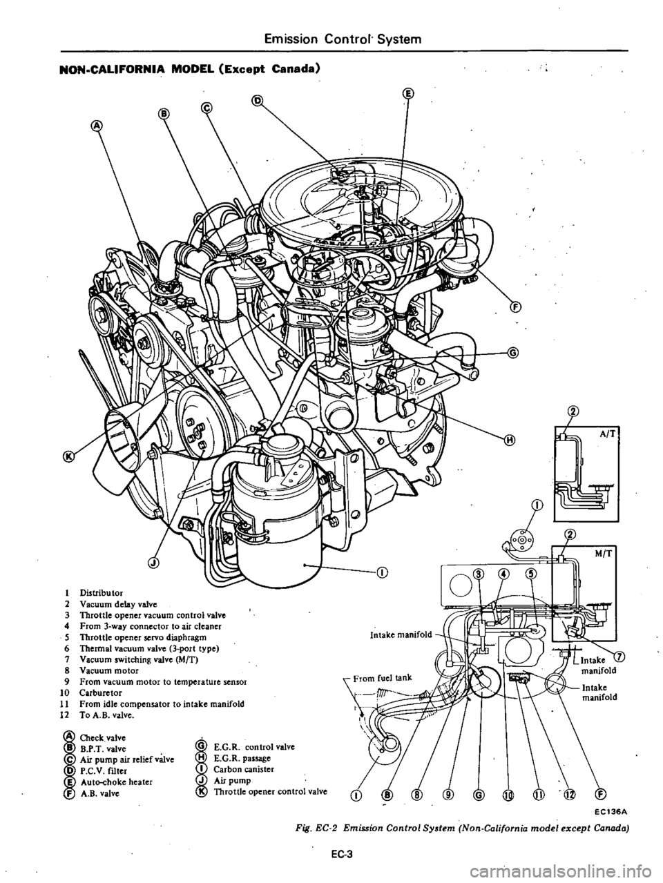
Emission
Control
System
NON
CALIFORNIA
MODEL
Except
Canada
5
CD
O@
j
l
t
AfT
M
T
1
Distributor
2
Vaellum
delay
valve
3
Throttle
opener
vacuum
control
valve
4
From
3
way
connector
to
air
cleaner
5
Throttle
opener
servo
diaphragm
6
Thermal
vacuum
valve
3
port
type
7
Vacuum
switching
valve
eMIT
8
Vacuum
motor
9
From
vacuum
motor
to
temperature
sensor
10
Carburetor
11
From
idle
compensator
to
intake
manifold
12
To
A
B
valve
rom
I
It
Intake
manifold
Check
valve
B
P
T
valve
C
Air
pump
air
relief
valve
D
P
C
V
mter
I
Auto
choke
heater
A
B
valve
I
E
G
R
control
valve
E
G
R
passage
Carbon
canister
Air
pump
Throttle
opener
control
valve
@
@
to
EC136A
Fig
EC
2
Emission
Control
System
Non
Californin
model
except
Canada
EC
3