DATSUN 510 1968 Service Repair Manual
Manufacturer: DATSUN, Model Year: 1968, Model line: 510, Model: DATSUN 510 1968Pages: 252, PDF Size: 12.2 MB
Page 181 of 252
176
CHAPTER
TInRTEEN
@
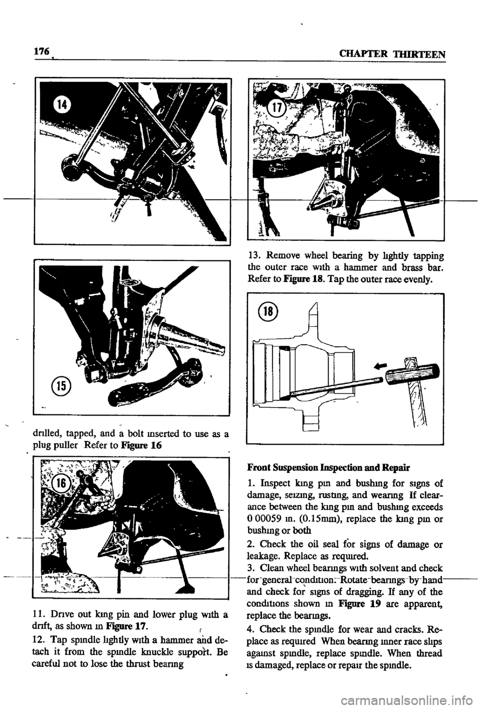
dnlled
tapped
and
a
bolt
mserted
to
use
as
a
plug
puller
Refer
to
Figure
16
r
r
t
t
rJ
11
Dnve
out
kmg
pin
and
lower
plug
With
a
dnft
as
shown
m
Figure
17
r
12
Tap
spmdle
hghtly
With
a
hanrmer
and
de
tach
it
from
the
spmdle
knuckle
suppoh
Be
careful
not
to
lose
the
thrust
bearmg
13
Remove
wheel
bearing
by
hghtly
tapping
the
outer
race
WIth
a
hanrmer
and
brass
bar
Refer
to
Figure
18
Tap
the
outer
race
evenly
@
Front
Suspension
Inspection
nnd
Repair
1
Inspect
kmg
pm
and
bushmg
for
SIgnS
of
damage
selZlDg
rustIng
and
wearmg
If
clear
ance
between
the
kmg
pm
and
bushmg
exceeds
000059
m
0
15mm
replace
the
kmg
pm
or
bushmg
or
both
2
Check
the
oil
seal
for
signs
of
damage
or
leakage
Replace
as
reqUIred
3
Clean
wheel
bearmgs
With
solvent
and
check
for
general
co
nmtIon
Rotate
bearmgs
by
hand
and
check
for
SIgnS
of
dragging
If
any
of
the
conmtJons
shown
m
Figure
19
are
apparent
replace
the
bearmgs
4
Check
the
spmdle
for
wear
and
cracks
Re
place
as
reqwred
When
beanng
mner
race
shps
agaJDst
spmdle
replace
spmdle
When
thread
IS
damaged
replace
or
reparr
the
spmdle
Page 182 of 252
FRONT
AXLE
FRONT
SUSPENSION
AND
STEERING
177
5
Check
front
hub
for
cracks
and
damage
Re
place
1f
defectIve
6
Check
thrust
bearmg
for
wear
damage
rust
and
ease
of
rotatIon
Replace
1f
defectIve
Front
Suspension
Installation
1
Remstallation
is
the
reverse
of
removal
2
Apply
hght
coatIng
of
multI
purpose
grease
to
all
shdmg
parts
3
Install
bushmg
carefully
so
that
grease
groove
IS
on
the
upper
Side
and
the
bushmg
Joint
is
faced
rearward
Remove
grease
mpple
and
dn11
grease
hole
through
bushmg
through
hole
With
an
0
1181
m
3mm
dn11
Remove
metal
shaVlDgs
and
burrs
Ream
the
mner
d1ameter
of
the
bushing
to
07878
to
0
7888
m
20
010
to
20035mm
4
Install
thrust
bearmg
so
that
the
covered
face
Side
is
upward
5
Push
up
the
bottom
of
the
spmdle
hghtly
Measure
clearance
and
select
a
spmdle
shim
to
prOVide
the
followmg
clearance
standard
Clearance
0
001
In
004mm
ShIms
are
available
m
vanous
thicknesses
6
FIt
kmg
pm
and
make
certam
It
operates
smoothly
7
Apply
sealer
to
new
plug
and
install
8
Install
bearmg
outer
race
Fill
wheel
hub
and
hub
cap
With
multI
purpose
grease
Fill
space
between
wheel
bearing
rollers
and
grease
seal
hp
pocket
With
multI
purpose
grease
Make
cer
tam
wheel
beanngs
are
coated
completely
9
Apply
multI
purpose
grease
to
spmdle
shaft
wheel
bearmg
washer
and
to
the
wheel
bearmg
lock
nut
10
Make
certam
that
no
dIrt
or
foreign
matenal
IS
permitted
m
contact
with
parts
or
grease
dunng
assembly
Wheel
Bearing
Adjustment
1
Install
spindle
nut
and
torque
to
23
1
to
24
6
ft
lb
3
2
to
3
4
kg
m
2
Turn
wheel
hub
a
few
tImes
m
both
the
clock
Wise
and
counterclockwISe
directIon
Recheck
the
spmdle
nut
tighmess
3
Back
off
spmdle
nut
from
40
to
70
degrees
until
hole
m
spmdle
and
nut
COinCIde
Insert
cotter
pm
and
bend
over
around
nut
4
Turn
wheel
hub
a
few
turns
in
both
d1rectIons
to
seat
bearmg
Check
the
startmg
torque
of
the
hub
With
a
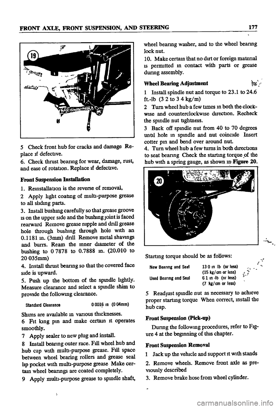
spring
gauge
as
shown
Figure
20
Startmg
torque
should
be
as
follows
New
Beanng
and
Seal
130
In
Ib
or
less
15
kgl
an
or
less
i
Used
Beanng
and
Seal
6
1
In
Ib
or
less
7
kgl
an
or
less
5
ReadJust
spmdle
nut
as
necessary
to
achieve
proper
startmg
torque
When
correct
mstall
the
hub
cap
Front
Suspension
Pick
up
Durmg
the
followmg
procedures
refer
to
FIg
ure
4
at
the
begmning
of
this
chapter
Front
Suspension
Removal
1
Jack
up
the
vehicle
and
support
It
With
stands
2
Remove
wheels
Remove
front
axle
as
pre
Viously
described
3
Remove
brake
hose
from
wheel
cylinder
Page 183 of 252
178
CHAPTER
mIRTEEN
4
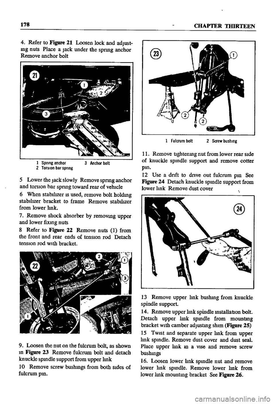
Refer
to
Figure
21
Loosen
lock
and
adJust
mg
nuts
Place
a
Jack
under
the
spnng
anchor
Remove
anchor
bolt
1
Spnng
anchor
2
TorSIon
bar
spnng
3
Anchor
boll
5
Lower
the
Jack
slowly
Remove
spnng
anchor
and
torsIOn
bar
spnng
toward
rear
of
vehicle
6
When
stablhzer
IS
used
remove
bolt
holdmg
stabIlIzer
bracket
to
frame
Remove
stabIlIzer
from
lower
hnk
7
Remove
shock
absorber
by
remoVlDg
upper
and
lower
fiXlng
nuts
8
Refer
to
Figure
22
Remove
nuts
1
from
the
front
and
rear
ends
of
tenSiOn
rod
Detach
tensIOn
rod
WIth
bracket
9
Loosen
the
nut
on
the
fulcrum
bolt
as
shown
m
Figure
23
Remove
fulcrum
bolt
and
detach
knuckle
spmdle
support
from
upper
hnk
10
Remove
screw
bushmgs
from
both
Sides
of
fulcrum
pm
@
1
Fulcrum
boll
2
Screw
bushmg
11
Remove
tIghtenmg
nut
from
lower
rear
SIde
of
knuckle
spmdle
support
and
remove
cotter
pm
12
Use
a
dnft
to
dnve
out
fulcrum
pm
See
Figure
24
Detach
knuckle
spmdle
support
from
lower
hnk
Remove
dust
cover
@
13
Remove
upper
hnk
bushmg
from
knuckle
spindle
support
14
Remove
upper
hnk
spindle
mstallation
bolt
Detach
upper
hnk
spmdle
from
mountIng
bracket
With
camber
adJustmg
shim
Figure
25
15
TWISt
and
separate
upper
hnk
from
upper
hnk
spmdle
Remove
dust
cover
and
dust
seal
Place
upper
hnk
m
a
VISe
and
remove
screw
bushmgs
16
Loosen
lower
hnk
spmdle
nut
and
remove
lower
hnk
spmdle
Remove
lower
hnk
from
lower
hnk
mountmg
bracket
See
FIgure
26
Page 184 of 252
FRONT
AXLE
FRONT
SUSPENSION
AND
STEERING
179
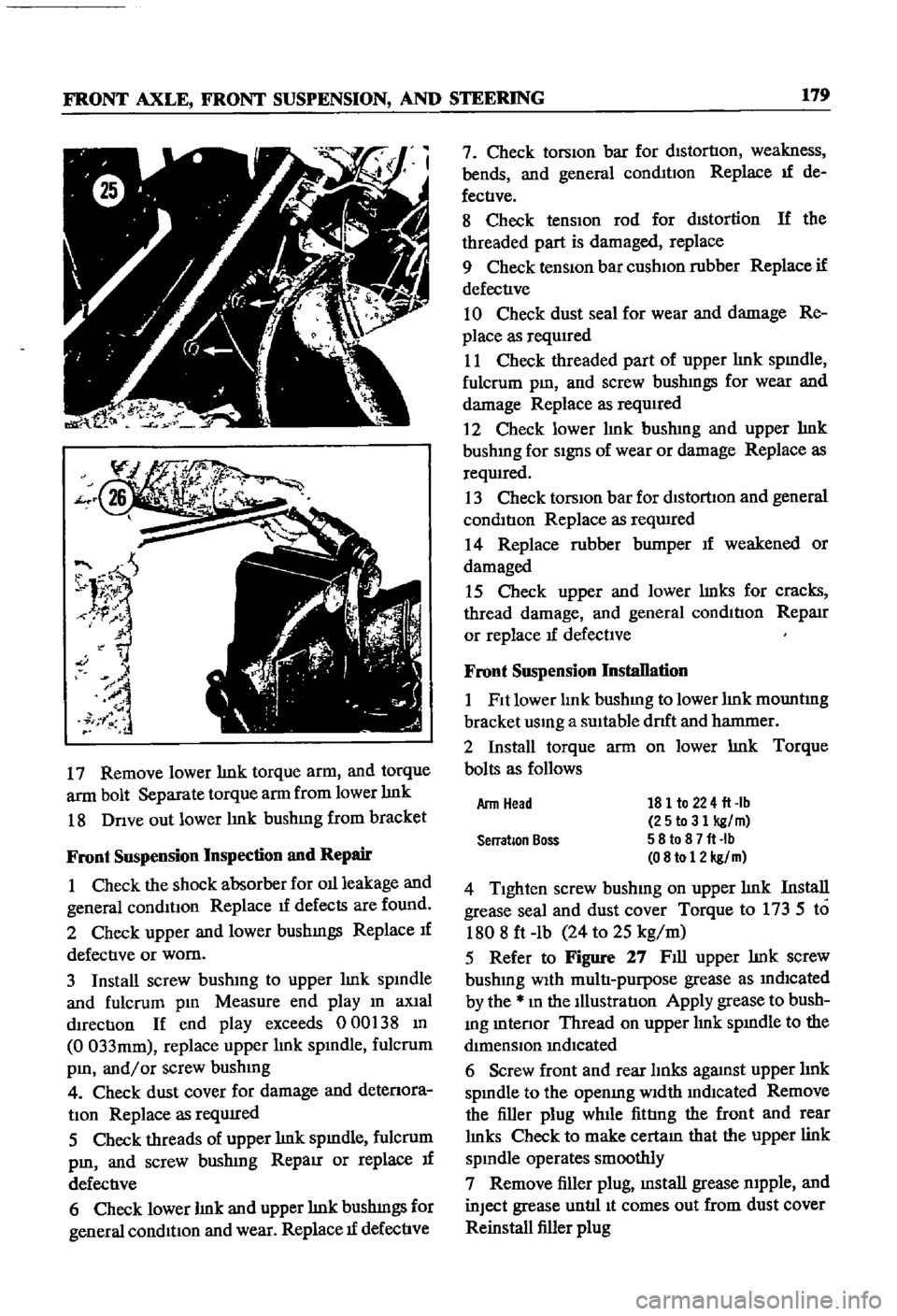
17
Remove
lower
lmk
torque
arm
and
torque
arm
bolt
Separate
torque
arm
from
lower
lmk
18
Dnve
out
lower
lmk
bushmg
from
bracket
Front
Suspension
Inspection
and
Repair
1
Check
the
shock
absorber
for
011
leakage
and
general
conditIon
Replace
1f
defects
are
found
2
Check
upper
and
lower
bushmgs
Replace
If
defective
or
worn
3
Install
screw
bushmg
to
upper
lmk
spmdle
and
fulcrum
pm
Measure
end
play
m
aXial
dIrection
If
end
play
exceeds
000
38
m
0
033mm
replace
upper
lmk
spmdle
fulcrum
pm
and
or
screw
bushmg
4
Check
dust
cover
for
damage
and
detenora
tIon
Replace
as
reqUIred
5
Check
threads
of
upper
lmk
spmdle
fulcrum
pm
and
screw
bushmg
RepaIr
or
replace
If
defective
6
Check
lower
lmk
and
upper
lmk
bushmgs
for
general
condition
and
wear
Replace
1f
defective
7
Check
torsion
bar
for
distortion
weakness
bends
and
general
conmtIon
Replace
If
de
fectIve
8
Check
tensIOn
rod
for
dIStortion
If
the
threaded
part
is
damaged
replace
9
Check
tenSiOn
bar
cushIOn
rubber
Replace
if
defective
10
Check
dust
seal
for
wear
and
damage
Re
place
as
requIred
11
Check
threaded
part
of
upper
lmk
spmdle
fulcrum
pm
and
screw
bushmgs
for
wear
and
damage
Replace
as
required
2
Check
lower
hnk
bushmg
and
upper
hnk
bushmg
for
SignS
of
wear
or
damage
Replace
as
reqwred
13
Check
torsIOn
bar
for
dlstorllon
and
general
condition
Replace
as
reqwred
14
Replace
rubber
bumper
If
weakened
or
damaged
15
Check
upper
and
lower
lmks
for
cracks
thread
damage
and
general
condition
RepaIr
or
replace
If
defectIve
Front
Suspension
Installation
1
Fit
lower
lmk
bushmg
to
lower
lmk
mountmg
bracket
usmg
a
SUItable
drlft
and
hanmIer
2
Install
torque
arm
on
lower
lmk
Torque
bolts
as
follows
181
to
224
fl
lb
25to31
kg
m
58
to
8
7
fl
Ib
08
to
12
kg
m
4
Tighten
screw
bushmg
on
upper
lmk
Install
grease
seal
and
dust
cover
Torque
to
173
5
to
1808
ft
lb
24
to
25
kg
m
5
Refer
to
Figure
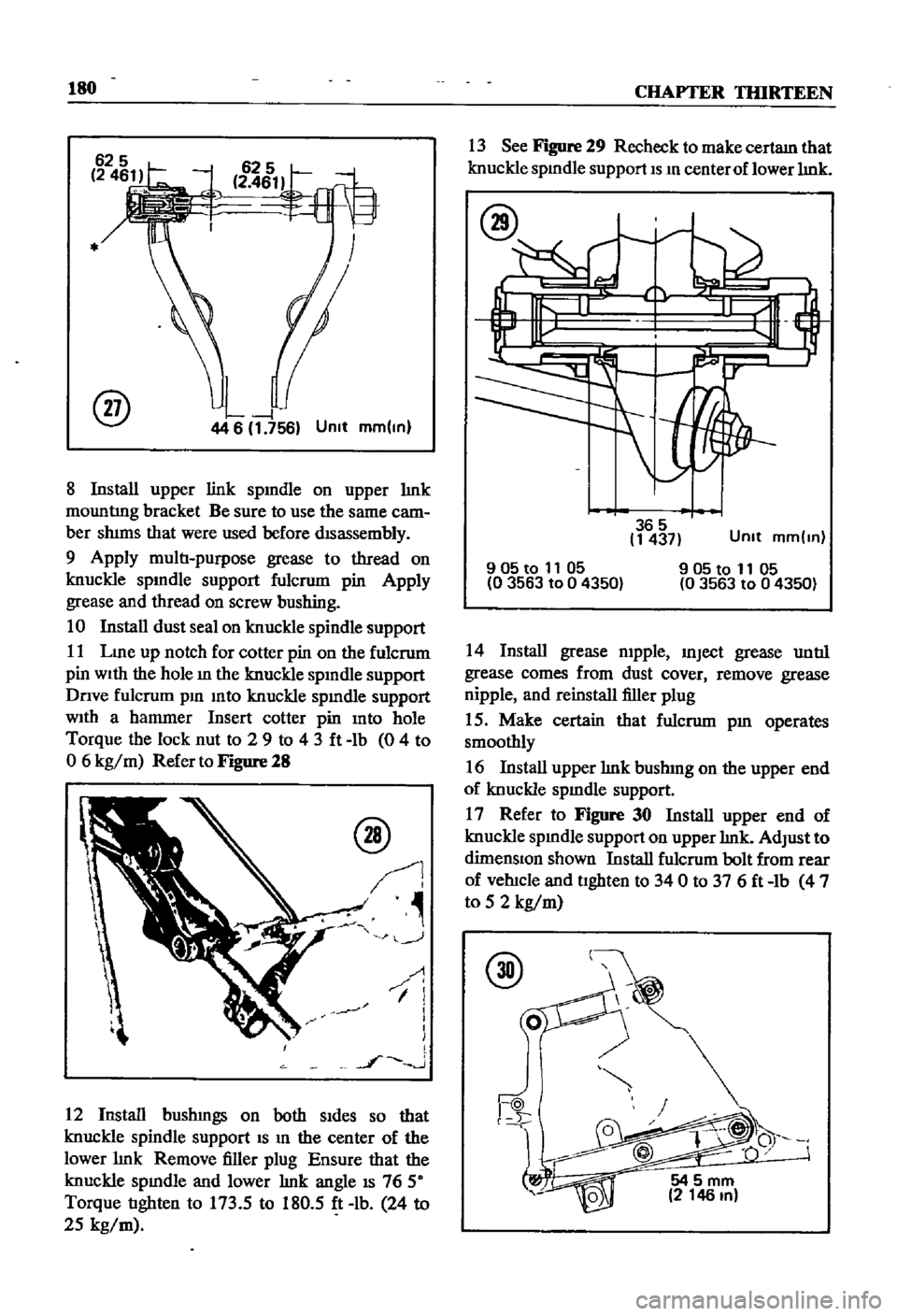
27
Fill
upper
lmk
screw
bushmg
With
multi
purpose
grease
as
mdlcated
by
the
m
the
Illustration
Apply
grease
to
bush
mg
mtenor
Thread
on
upper
lmk
spmdle
to
the
dimenSIOn
mdIcated
6
Screw
front
and
rear
lInks
agaJnst
upper
hnk
spmdle
to
the
openmg
Width
mdlcated
Remove
the
filler
plug
while
fittIng
the
front
and
rear
lmks
Check
to
make
cectam
that
the
upper
link
spmdle
operates
smoothly
7
Remove
filler
plug
mstall
grease
mpple
and
inJect
grease
untIl
It
comes
out
from
dust
cover
Reinstall
filler
plug
Arm
Head
Serration
Boss
Page 185 of 252
180
CHAPTER
TIlIRTEEN
@
44
6
1
756
Unit
mm
ln
8
Install
upper
link
spmdle
on
upper
lmk
mountIng
bracket
Be
sure
to
use
the
same
cam
ber
shims
that
were
used
before
disassembly
9
Apply
multi
purpose
grease
to
thread
on
knuckle
spmdle
support
fulcrum
pin
Apply
grease
and
thread
on
screw
bushing
10
Install
dust
seal
on
knuckle
spindle
support
11
Lme
up
notch
for
cotter
pin
on
the
fulcrum
pin
With
the
hole
m
the
knuckle
spmdle
support
Dnve
fulcrum
pm
mto
knuckle
spmdle
support
With
a
hammer
Insert
cotter
pin
mto
hole
Torque
the
lock
nut
to
2
9
to
43ft
lb
0
4
to
o
6
kg
m
Refer
to
Figure
28
@
J
J
I
1
i
1
l
l
J
J
12
Install
bushmgs
on
both
Sides
so
that
knuckle
spindle
support
IS
m
the
center
of
the
lower
lmk
Remove
filler
plug
Ensure
that
the
knuckle
spmdle
and
lower
lmk
angle
IS
76
50
Torque
tighten
to
173
5
to
180
5
ft
lb
24
to
25
kg
m
13
See
Figure
29
Recheck
to
make
certam
that
knuckle
spmdle
support
IS
m
center
of
lower
lmk
365
1437
Unit
mm
ln
905to
11
05
0
3563
to
0
4350
905t01105
03563
to
04350
14
Install
grease
mpple
mJect
grease
until
grease
comes
from
dust
cover
remove
grease
nipple
and
reinstall
filler
plug
15
Make
certain
that
fulcrum
pm
operates
smoothly
16
Install
upper
lmk
bushmg
on
the
upper
end
of
knuckle
spmdle
support
17
Refer
to
Figure
30
Install
upper
end
of
knuckle
spmdle
support
on
upper
lmk
AdJust
to
dimenSIOn
shown
Install
fulcrum
bolt
from
rear
of
vehicle
and
tighten
to
340
to
376ft
lb
4
7
to
5
2
kg
m
@
54
5
mm
2
146
In
Page 186 of 252
FRONT
AXLE
FRONT
SUSPENSION
AND
STEERING
181
18
TIghten
nut
on
rear
end
of
tension
rod
to
compress
rubber
bushings
to
1
315
m
334
fi2
mm
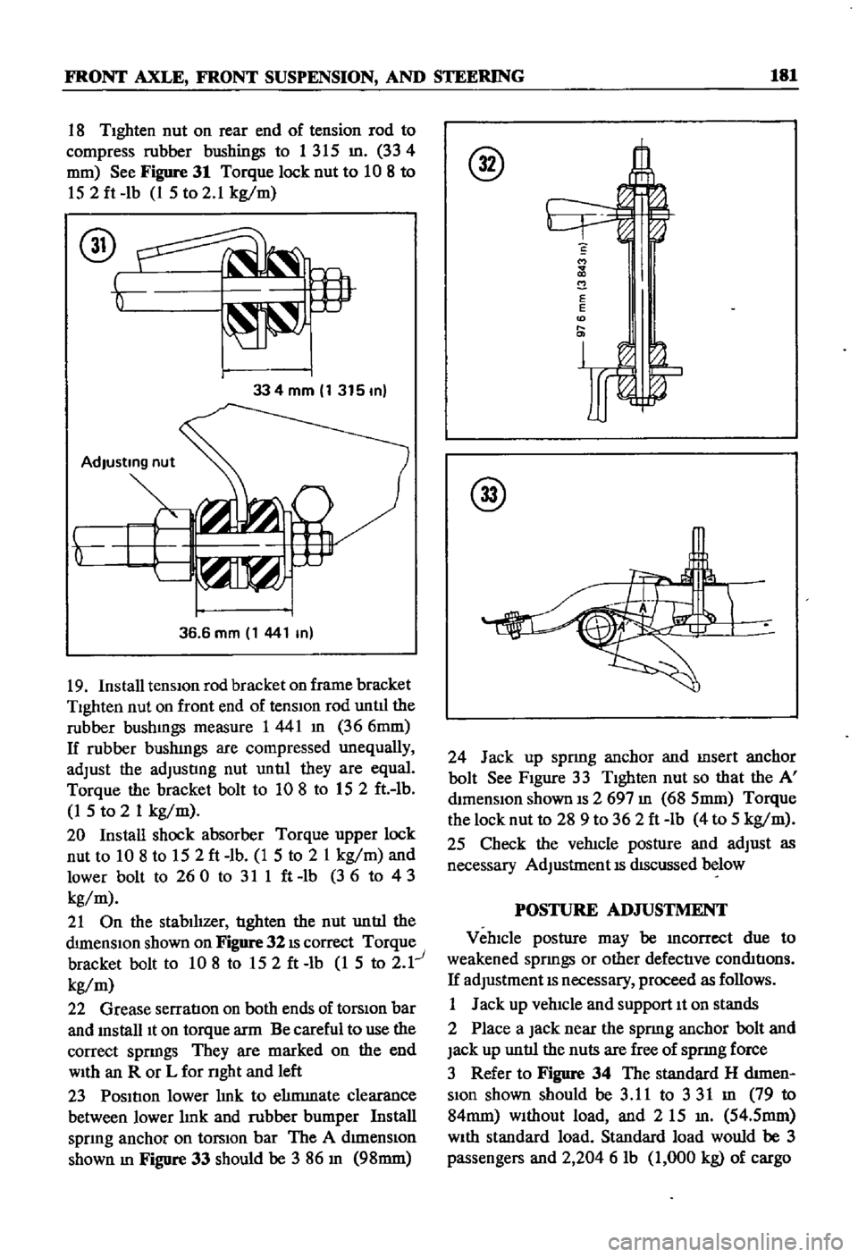
See
Figure
31
Torque
lock
nut
to
10
8
to
152ft
lb
1
5
to
2
1
kg
m
334mm
1315m
36
6
mm
1
441
m
19
Install
tensiOn
rod
bracket
on
frame
bracket
Tighten
nut
on
front
end
of
tensIOn
rod
untll
the
rubber
bushmgs
measure
1441
m
366mm
If
rubber
bushmgs
are
compressed
unequally
adJust
the
adJusting
nut
until
they
are
equal
Torque
the
bracket
bolt
to
108
to
152
ft
lb
1
5
to
2
1
kg
m
20
Install
shock
absorber
Torque
upper
lock
nut
to
10
8
to
152ft
lb
1
5
to
2
1
kg
m
and
lower
bolt
to
260
to
311ft
lb
36
to
43
kg
m
21
On
the
stabilizer
tighten
the
nut
until
the
dimenSIOn
shown
on
Figure
32
IS
correct
Torque
bracket
bolt
to
10
8
to
152ft
lb
1
5
to
2
1
kg
m
22
Grease
serratIon
on
both
ends
of
torSiOn
bar
and
mstalllt
on
torque
arm
Be
careful
to
use
the
correct
spnngs
They
are
marked
on
the
end
WIth
an
R
or
L
for
nght
and
left
23
Position
lower
hnk
to
ehmmate
clearance
between
lower
hnk
and
rubber
bumper
Install
spnng
anchor
on
torsIOn
bar
The
A
dImenSiOn
shown
m
Figure
33
should
be
3
86
m
98mm
S
M
2
E
E
D
@
24
Jack
up
spnng
anchor
and
msert
anchor
bolt
See
Figure
33
Tighten
nut
so
that
the
A
mmenslon
shown
IS
2
697
m
68
5mm
Torque
the
lock
nut
to
28
9
to
362ft
lb
4
to
5
kg
m
25
Check
the
vehicle
posture
and
adJust
as
necessary
AdJustment
IS
dIScussed
below
POSTURE
AD
JUSTMENT
Vehicle
posture
may
be
mcorrcct
due
to
weakened
sprmgs
or
other
defective
conmtions
If
adJustment
IS
necessary
proceed
as
follows
1
Jack
up
vehicle
and
support
It
on
stands
2
Place
a
Jack
near
the
sprmg
anchor
bolt
and
Jack
up
until
the
nuts
are
free
of
spnng
force
3
Refer
to
Figure
34
The
standard
H
d1men
Slon
shown
should
be
3
11
to
331
m
79
to
84mm
Without
load
and
2
15
m
54
5mm
WIth
standard
load
Standard
load
would
be
3
passengers
and
2
204
6
lb
1
000
kg
of
cargo
Page 187 of 252
182
CHAPTER
TIllRTEEN
@
AdJust
the
anchor
bolt
adJustmg
nut
until
the
vehicle
posture
IS
correct
One
complete
turn
of
the
nut
will
change
the
vertIcal
measurement
by
approXlmately
0
133
in
3
Smm
WHEEL
AUGNMENT
Due
to
the
speclahzed
eqwpment
required
wheel
ahgnment
should
be
referred
to
a
Datsun
dealer
or
a
wheel
alignment
specIahst
The
fol
lowmg
specmcatIons
apply
to
the
pick
up
Caster
Camber
Kmg
Pm
Inclmatlon
Toe
In
1
50
1
15
6015
o
0787
to
0
1181
In
2
to
3mm
360
31
Steenng
Angle
Inner
Steenng
Angle
Outer
STEERING
SYSTEM
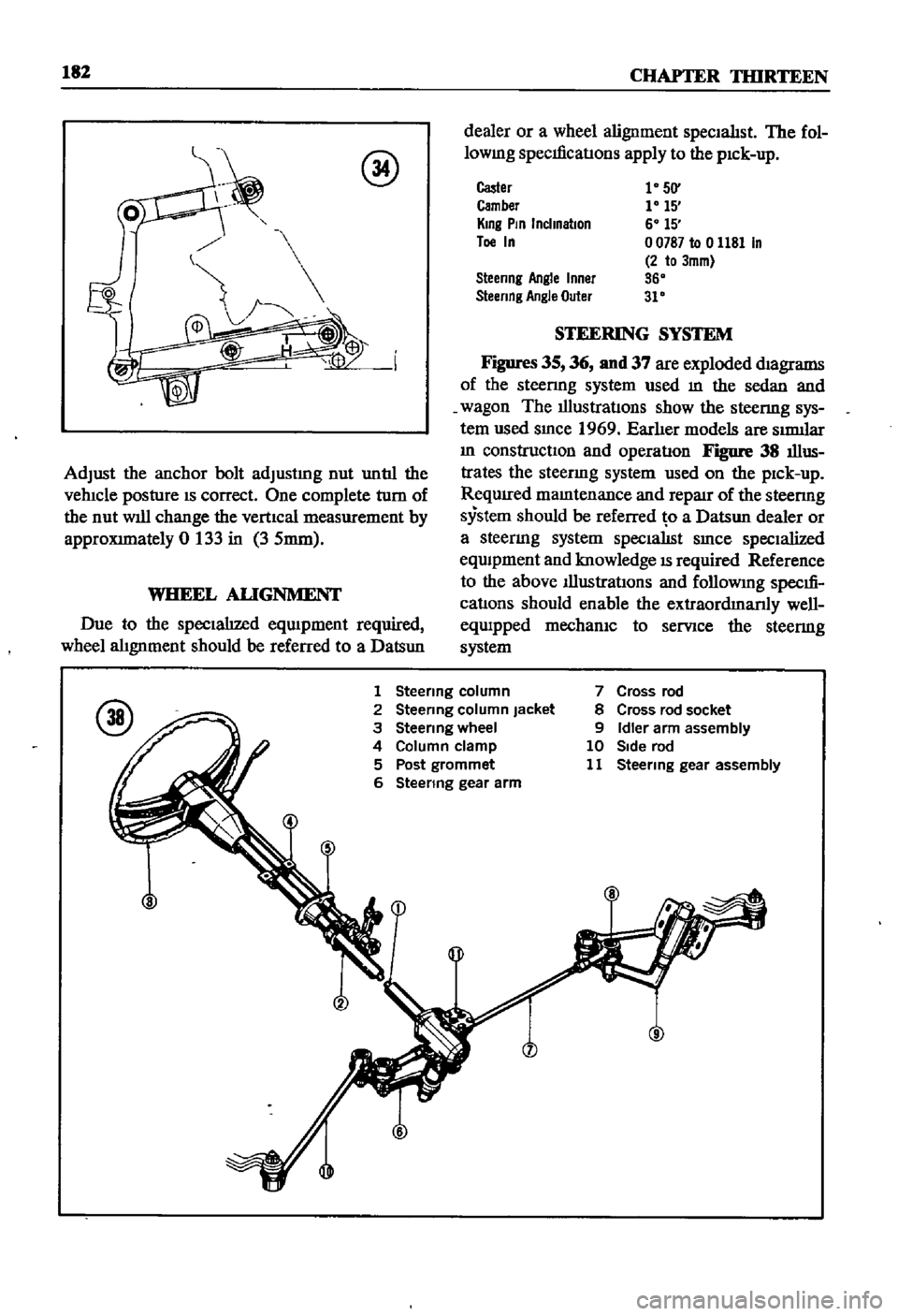
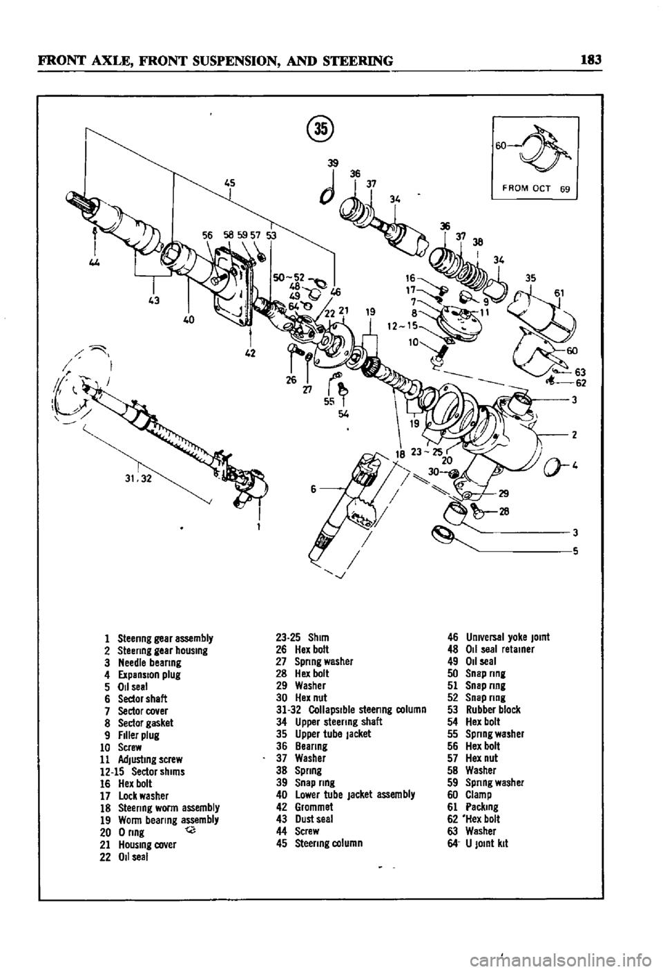
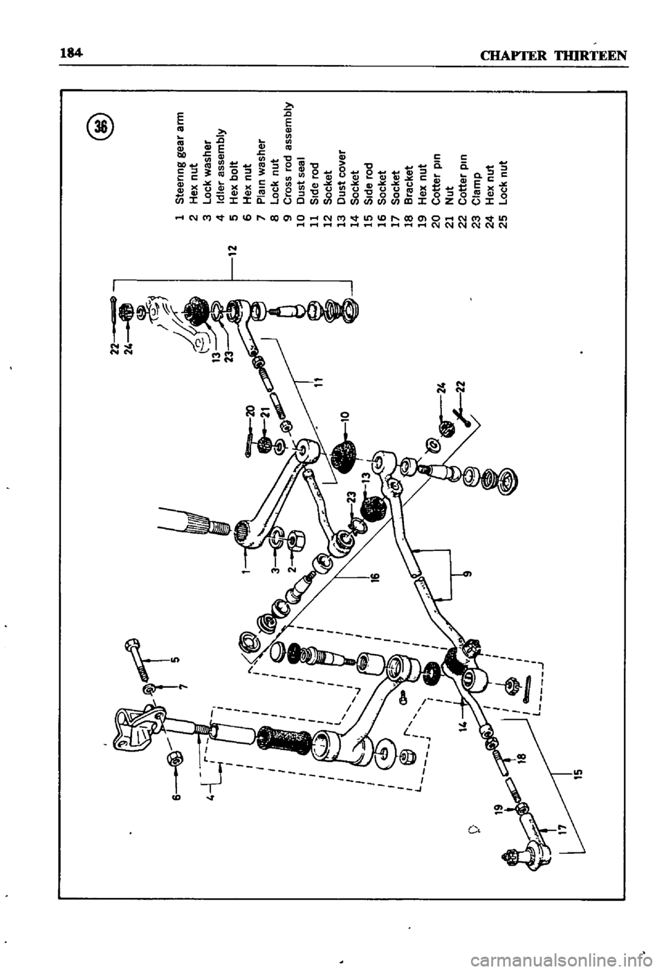
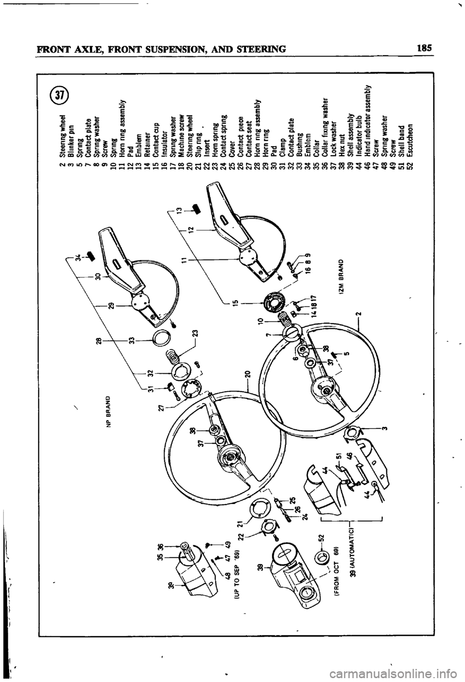
Figures
35
36
nnd
37
are
exploded
magrams
of
the
steenng
system
used
m
the
sedan
and
wagon
The
illustratIons
show
the
steenng
sys
tem
used
smce
1969
Earher
models
are
SImllar
m
constructiOn
and
operatIon
Figure
38
illus
trates
the
steenng
system
used
on
the
pick
up
ReqUIred
mamtenance
and
repaJr
of
the
steenng
system
should
be
referred
o
a
Datsun
dealer
or
a
steermg
system
specialISt
smce
specialized
eqwpment
and
knowledge
IS
required
Reference
to
the
above
Illustrations
and
followmg
specm
cations
should
enable
the
extraordmanly
well
equipped
mechanIC
to
serVice
the
steermg
system
1
Steenng
column
2
Steermg
column
Jacket
3
Steenng
wheel
4
Column
clamp
5
Post
grommet
6
Steenng
gear
arm
7
Cross
rod
8
Cross
rod
socket
9
Idler
arm
assembly
10
Side
rod
11
Steermg
gear
assembly
Page 188 of 252
FRONT
AXLE
FRONT
SUSPENSION
AND
STEERING
183
4J
40
1
Steenng
gear
assembly
2
Steenng
gear
hOUSing
3
Needle
beanng
4
ExpanSion
plug
5
011
seal
6
Sedor
shaft
7
Sector
cover
8
Sector
gasket
9
Filler
plug
10
Screw
11
Adjusting
screw
12
15
Sector
shims
16
Hex
bolt
17
Lock
washer
18
Steenng
worm
assembly
19
Wonn
bearing
assembly
200nng
t
21
HOUSing
cover
22
011
seal
@
w
39
JJii
3738
I
34
8
11
12
W63
62
23
25
Shim
26
Hex
bolt
27
Spnng
washer
28
Hex
bolt
29
Washer
30
Hex
nut
31
32
Collapsible
steenng
column
34
Upper
steenng
shaft
35
Upper
tube
Jacket
36
Beanng
37
Washer
38
Spnng
39
Snap
nng
40
Lower
tube
jacket
assembly
42
Grommet
43
Dust
seal
44
Screw
45
Steenng
column
F
ROM
OCT
69
3
3
5
46
Umversal
yoke
JOint
48
011
seal
retainer
49
011
seal
50
Snap
nng
51
Snap
nng
52
Snap
nng
53
Rubber
block
54
Hex
bolt
55
Spnng
washer
56
Hex
bolt
57
Hex
nut
5B
Washer
59
Spnng
washer
60
Clamp
61
Paclung
62
Hex
bolt
63
Washer
64
U
JOint
kit
Page 189 of 252
15
7
5
l
J
@
1
Steermg
gea
r
arm
2
Hex
nut
3
Lock
washer
4
Idler
assembly
12
5
Hex
bolt
6
Hex
nut
7
Plam
washer
8
Lock
nut
9
Cross
rod
assembly
10
Dust
seal
11
Side
rod
12
Socket
13
Dust
cover
14
Socket
15
Side
rod
16
Socket
17
Socket
18
Bracket
19
Hex
nut
20
Cotter
pm
21
Nut
22
Cotter
pm
23
Clamp
24
Hex
nut
25
Lock
nut
00
Page 190 of 252
NP
BRAND
3536
48
47
49
UP
TO
SEP
69
15
10
l
f
J
r
1
L
IZM
BRAND
39
39
AUTOMATIC
2
Steering
wheel
@
3
Blinker
pin
5
Spring
7
Contact
plate
8
Spring
washer
9
Screw
10
Spring
11
Horn
ring
assembly
12
Pad
13
Emblem
14
Retainer
15
Contact
cup
16
Insulator
17
Spring
washer
18
Machine
screw
20
Steering
wheel
21
Slip
ring
22
Insert
23
Horn
spring
24
Contact
spring
25
Cover
26
Contact
pleca
27
Contact
seat
28
Horn
ring
assembly
29
Horn
ring
30
Pad
31
Clamp
32
Contact
plate
33
Bushing
34
Emblem
35
Collar
36
Collar
fiXing
washer
37
Lock
washer
38
Hex
nut
39
Shell
assembly
44
Indicator
bulb
46
Hand
indicator
assembly
47
Scraw
48
Spring
washer
49
Screw
51
Shell
band
52
Escutcheon
o
I
l
I
l
i
J
I
Ci
l
QD
II
L