DATSUN 510 1968 Service Owner's Manual
Manufacturer: DATSUN, Model Year: 1968, Model line: 510, Model: DATSUN 510 1968Pages: 252, PDF Size: 12.2 MB
Page 21 of 252
16
CHAPTER
TIlREE
sary
Also
check
all
parts
for
mlSaltgnment
and
uneven
wear
TRANSMISSION
1
Difficult
to
mesh
gears
Make
certam
the
clutch
pressure
plate
and
re
lease
beanng
are
m
good
condItion
The
trouble
can
be
caused
by
worn
gears
shaft
and
or
bear
mgs
DISassemble
and
repaIr
as
requIred
Also
can
be
caused
by
msufficlent
operatmg
stroke
due
to
worn
or
loose
sltdmg
parts
or
a
defective
synchronIZer
DIsassemble
carefully
InSpect
and
replace
as
requIred
2
Gears
slip
out
of
mesh
Generally
thIS
trouble
occurs
when
the
mterlock
plunger
check
ball
and
or
spnng
IS
weakened
or
worn
The
trouble
can
also
be
caused
by
worn
fork
rod
ball
groove
damaged
bearings
or
dam
aged
gears
DIsassemble
carefully
mspect
and
replace
as
required
3
NOIse
If
nOISes
are
heard
wIth
the
engme
idlmg
and
the
clutch
disengaged
the
nOIse
IS
probably
conung
from
the
transmISSIOn
Several
Items
can
cause
nOISes
either
smgly
or
m
combmatIon
Check
the
qualIty
and
quantity
of
lubrIcant
in
the
trans
mISSIon
Replace
or
replenISh
as
necessary
Worn
bearIngs
wIll
usually
produce
a
lugh
humming
at
hIgh
speed
and
a
cycltc
knockIng
sound
at
low
speed
Worn
or
damaged
splInes
and
bushmgs
will
also
cause
nOIse
BRAKES
1
Brake
pedal
goes
to
floor
There
are
numerous
causes
for
thIS
includIng
excessIvely
worn
Itnmgs
aIr
in
the
hydraultc
sys
tem
leaky
brake
lmes
leaky
wheel
cylmders
or
leaky
or
worn
master
cylmder
Check
for
leaks
and
thIn
brake
linmgs
Bleed
and
adjust
the
brakes
If
thIS
doesn
t
cure
the
trouble
rebwld
wheel
cylmders
a
nd
or
master
cylmder
2
Spongy
pedal
Normally
caused
by
aIr
m
the
system
blee
d
and
adjust
the
brakes
3
Brakes
pull
Check
brake
adjustment
Also
check
for
contam
inated
brake
Itmngs
from
leaks
leaky
wheel
cyltnders
loose
caltpers
frozen
or
seIZed
pIstons
and
restrIcted
brake
lmes
or
hoses
In
addItion
check
front
end
alignment
and
suspensIOn
dam
age
such
as
broken
front
or
rear
sprmgs
shocks
etc
Check
condItIon
of
tIres
4
Brakes
squeal
or
chatter
Check
brake
lmmg
thickness
and
brake
drum
roundness
Ensure
that
the
shoes
have
cham
ferred
ends
and
are
not
loose
Inspect
the
condI
tion
of
the
rotors
on
the
front
wheel
dISC
brakes
to
make
certain
they
are
not
scored
or
damaged
Clean
away
all
dIrt
on
shoes
pads
rotors
or
drums
5
Draggmg
brakes
Check
brake
adjustment
includmg
handbrake
Check
for
broken
or
weak
shoe
return
springs
swollen
rubber
parts
due
to
unproper
brake
flUId
or
other
contammatIon
Clean
or
replace
de
fectIve
parts
6
Hard
pedal
Check
brake
linmgs
for
contammation
Also
check
for
restrIcted
brake
lines
and
hoses
7
High
speed
fade
Check
for
dIstorted
or
out
of
round
drums
and
contamInated
brake
lmmgs
Make
certam
the
recommended
brake
flUId
IS
used
Dram
entIre
system
and
refill
If
In
doubt
8
Pulsatmg
pedal
Check
for
dIStorted
or
out
of
round
drums
or
rotors
Check
for
excessIVe
brake
dISC
run
out
STEERING
AND
SUSPENSION
NOTE
Unusual
steermg
pullmg
or
wandermg
IS
usually
caused
by
bent
or
otherwise
mIsaligned
suspenszon
parts
Because
of
the
speCialized
equIp
ment
reqUired
to
evaluate
and
correct
these
faults
It
IS
recommended
t
tat
servIce
to
the
steermg
and
suspension
system
be
referred
to
your
Datsun
dealer
oca
quallfied
specrallst
m
thiS
field
1
VibratIOn
felt
m
steermg
wheel
VIbratIon
can
be
caused
by
several
thmgs
includ
ing
lll1proper
aIr
pressure
m
tIres
uneven
wear
Page 22 of 252
TROUBLESHOOTING
17
of
tIre
loose
wheels
unproper
adjustment
or
wear
of
front
wheel
bearIngs
faulty
wheel
align
ment
or
wear
of
transverse
lInk
and
tension
rod
bushings
Inspect
all
parts
carefully
for
wear
or
damage
Replace
or
replUI
parts
as
required
2
Shock
transmltled
through
steering
wheel
This
is
usually
most
noticeable
when
traveling
over
bad
roads
at
relatively
high
speeds
Causes
Include
damage
to
the
idler
ann
insuffiCient
tIghtening
of
steenng
gear
box
wear
of
the
steer
Ing
linkage
and
wear
of
the
suspension
ball
joint
Inspect
all
parts
for
wear
or
damage
Refer
to
Chapter
ThIrteen
for
service
or
repair
you
can
perform
and
for
procedures
which
should
be
referred
to
your
deal
r
3
Shlmmymg
This
is
usually
most
noticeable
when
a
specIfic
speed
IS
attained
and
will
normally
repeat
at
that
speed
Causes
are
generally
unbalanced
wheels
unproper
adjustment
of
steenng
gear
insuffi
cient
backlash
malfunction
of
the
shock
ab
sorbers
or
loose
bolts
for
the
strut
mountIng
Reparr
or
replace
defective
parts
as
required
Refer
to
Chapter
Thirteen
4
Wandermg
of
car
m
one
dlrectlOnl
This
problem
can
be
caused
by
improper
air
pressure
loose
wheel
nuts
difference
in
tire
tread
wear
from
left
to
right
side
Incorrect
adjustment
of
wheel
bearings
defectIve
wheel
beanngs
collapsing
or
twistIng
of
front
spnng
or
Incorrect
wheel
alignment
Also
binding
of
the
brake
shoes
worn
bushings
in
the
transverse
link
or
the
tension
rod
and
deformation
of
s
enng
lInkage
and
suspension
link
can
cause
wander
Carefully
iuspect
all
parts
for
looseness
and
wear
and
re
place
or
repaIr
as
required
In
some
c
ases
a
de
fective
rear
suspension
may
also
cause
the
vehicle
to
wander
5
InstabIlity
Instability
can
be
caused
by
unproper
tIre
pres
sures
worn
bushings
in
the
transverse
link
and
tension
rod
mcorrect
wheel
alignment
worn
steenng
linkage
Incorrect
adjustment
of
steer
ing
gear
and
unbalanced
wheels
Inspect
all
parts
carefully
for
wear
and
damage
Adjust
repair
or
replace
as
required
6
Heavy
feelmg
m
steering
This
can
be
caused
by
improper
tIre
pressures
insuffiCient
or
contamInated
lubncant
in
gear
box
damage
or
insuffiCient
grease
In
suspeuslon
ball
Joint
damaged
or
badly
adjusted
wheel
bearIngs
worn
or
damaged
steermg
gear
dam
age
of
upper
strut
bearing
and
mterference
of
steenng
column
With
turn
signal
SWitch
Inspect
all
parts
carefully
for
wear
and
damage
Adjust
repair
or
replace
as
required
7
ExceSSIve
play
m
steermg
wheel
This
is
usually
caused
by
Incorrect
adjustment
of
the
steenng
gear
worn
bushings
in
the
steering
linkage
or
Idler
arm
mcorrect
adjustment
of
the
front
wheel
bearings
worn
bushIngs
in
the
trans
verse
lInk
and
tension
rod
Carefully
inspect
all
parts
for
wear
or
damage
Adjust
repair
or
re
place
as
reqUIred
TIRE
WEAR
ANALYSIS
Abnormal
tIre
wear
should
always
be
ana
lyzed
to
deternune
the
cause
The
most
common
are
Incorrect
tIre
pressure
improper
dnving
overloading
and
Incorrect
wheel
ahgDment
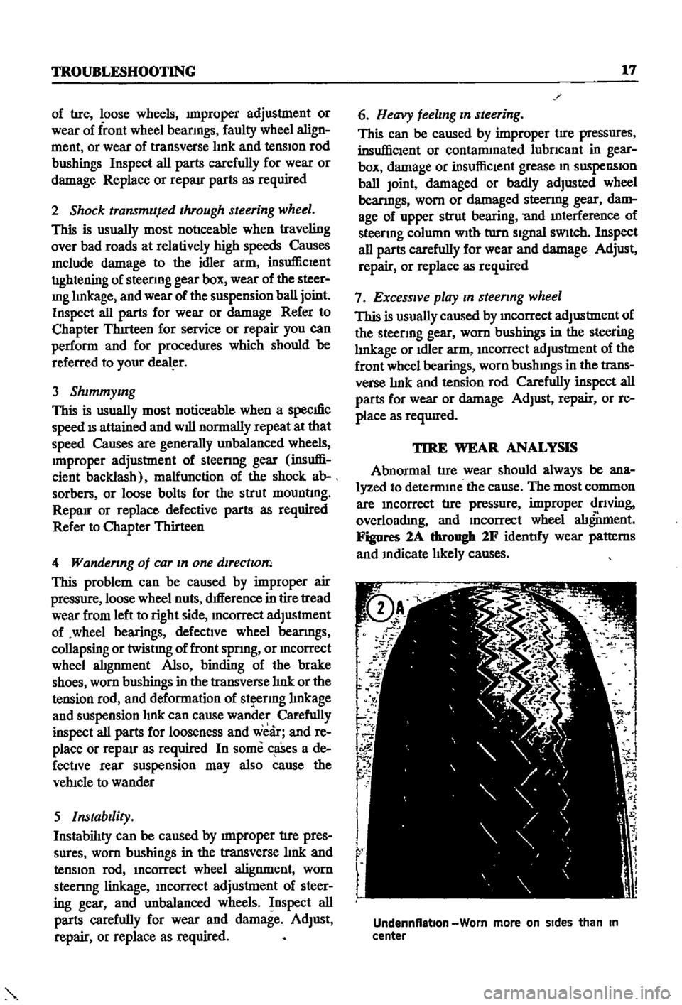
Figures
2A
through
2F
identify
wear
patterns
and
mdicate
likely
causes
Of
I
1
l
D
1
Undennflatlon
Worn
more
on
Sides
than
In
center
Page 23 of 252
18
CHAP1
lER
THlREE
c
c
c
ce
J
1
Ii
j
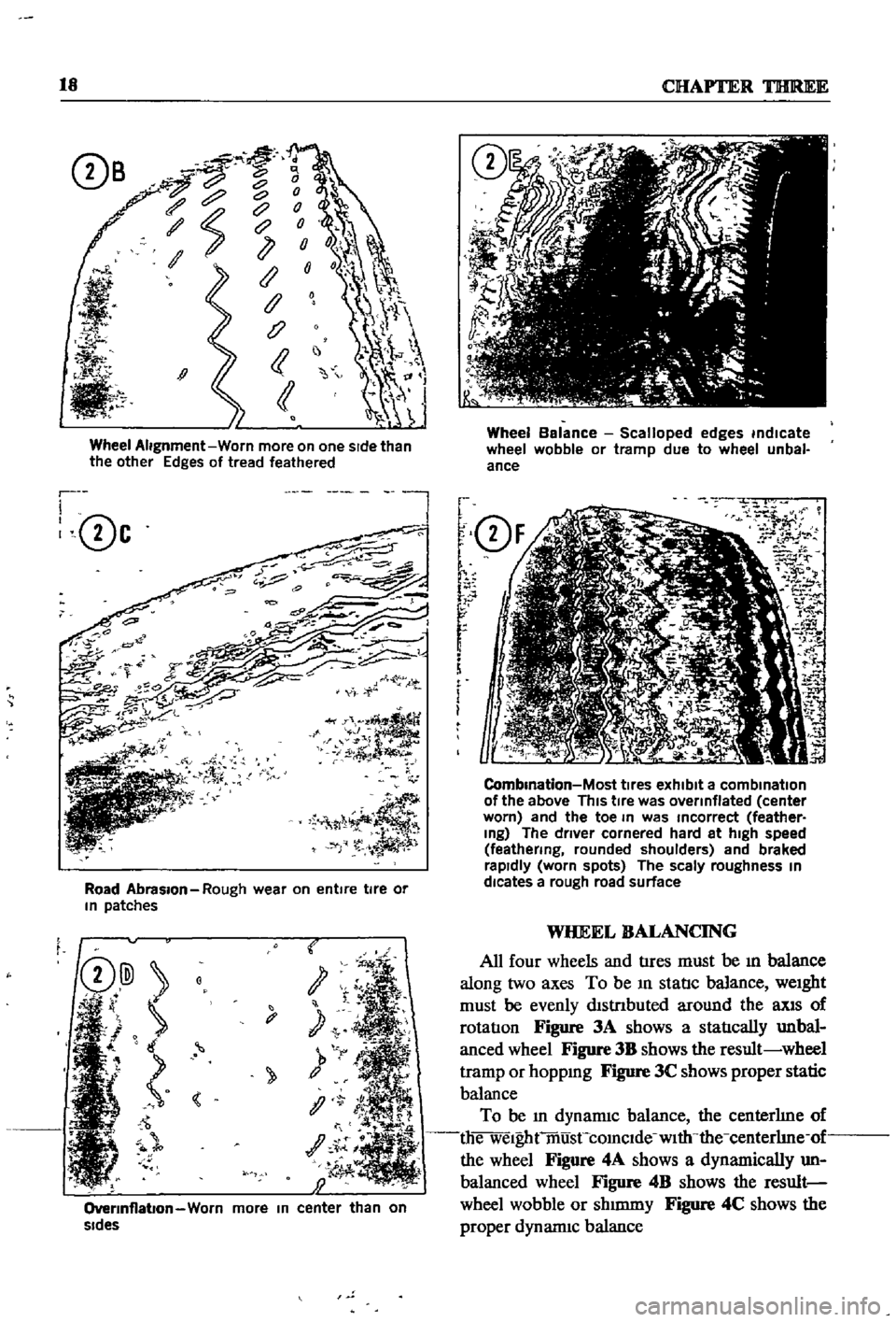
Wheel
Alignment
Worn
more
on
one
sIde
than
the
other
Edges
of
tread
feathered
r
I
0c
l
Road
Abrasion
Rough
wear
on
entire
tire
or
In
patches
t
y
1
OverInflabon
Worn
more
In
center
than
on
sides
Wheel
Balance
Scalloped
edges
indicate
wheel
wobble
or
tramp
due
to
wheel
unbal
ance
f
Q
F
r
r
r
f
i
m
i
O
2
7
iK
J
1
J
i
i
5J
CombInation
Most
tIres
exhibit
a
combination
of
the
above
This
tIre
was
overinflated
center
worn
and
the
toe
In
was
Incorrect
feather
Ing
The
driver
cornered
hard
at
high
speed
feathering
rounded
shoulders
and
braked
rapidly
worn
spots
The
scaly
roughness
In
dlcates
a
rough
road
surface
WHEEL
BALANCING
All
four
wheels
and
tIres
must
be
ill
balance
along
two
axes
To
be
ill
statIc
balance
weight
must
be
evenly
dlstnbuted
around
the
llXlS
of
rotatIon
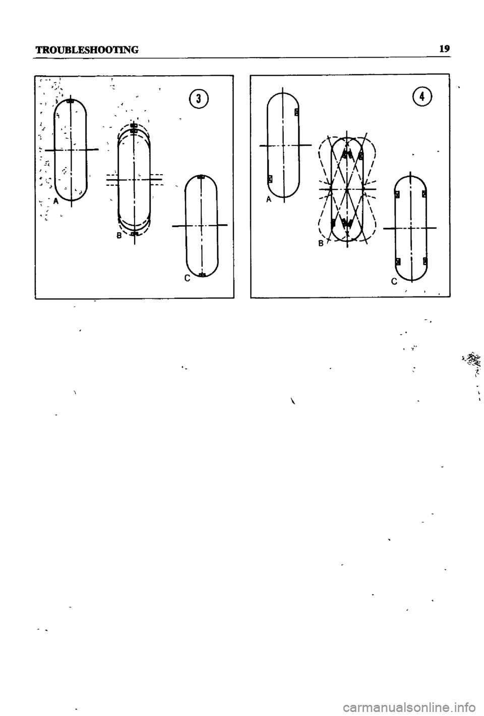
Figure
3A
shows
a
statIcally
unbal
anced
wheel
Figure
3B
shows
the
result
wheel
tramp
or
hoppmg
Figure
3C
shows
proper
static
balance
To
be
ill
dynamiC
balance
the
centerhne
of
die
welghtmusCcomclde
with
the
centerhne
of
the
wheel
Figure
4A
shows
a
dynamically
un
balanced
wheel
Figure
4B
shows
the
result
wheel
wobble
or
shmuny
Figure
4C
shows
the
proper
dynannc
balance
Page 24 of 252
rROUBLESIlOOTlNG
CD
CD
t
Page 25 of 252
CHAPTER
FOUR
ENGINE
AND
IGNITION
TUNE
UP
For
best
performance
and
economy
care
must
be
taken
in
perfornnng
tune
ups
While
accuracy
is
required
the
task
IS
not
d1flicult
if
the
steps
m
tlus
chapter
are
followed
carefully
Cars
used
pnmarily
m
CIty
stop
and
go
dnv
ing
WIll
reqwre
attention
more
frequently
than
those
used
on
highways
ThIs
is
because
the
engme
does
not
reach
full
operatIng
temperature
ConsequentlY
valves
tend
to
stick
compression
drops
and
engme
operatIon
becomes
rough
A
tune
up
IS
adVISable
every
6
000
miles
or
sooner
dependmg
on
type
of
driving
Every
12
000
nu1es
the
spark
plugs
and
ignitIon
break
er
pomts
should
be
replaced
not
Just
cleaned
and
adjusted
A
mmor
tune
up
consISts
of
checking
battery
condItIon
cleanmg
gapping
or
replacmg
spark
plugs
and
dIstnbutor
breaker
pomts
adjustIng
dIStnbutor
dwell
angle
adjusting
IgnitIon
tun
mg
and
settIng
the
carburetor
Idle
mixture
and
idle
speed
A
major
wne
up
includes
the
above
items
plus
igllltIon
compressIOn
valve
clear
ance
carburetor
emISsion
control
deVIce
and
electncal
checks
and
adjustments
Tune
up
Equipment
Required
The
follOWIng
eqUIpment
IS
required
Chap
ter
Two
provides
a
bnef
descnption
of
the
test
eqwpment
I
Voltmeter
ammeter
and
ohmmeter
2
Hydrometer
3
CompressIOn
tester
4
Vacuum
gauge
s
Dwell
meter
6
Tachometer
7
I
StrobOSCOpIC
tmung
lIght
8
Feeler
gauges
9
Torque
wrench
10
Assorted
hand
tools
Connection
of
Tune
up
Equipment
Follow
the
manufacturer
s
recommendations
for
the
use
of
test
eqwpment
If
pOSSible
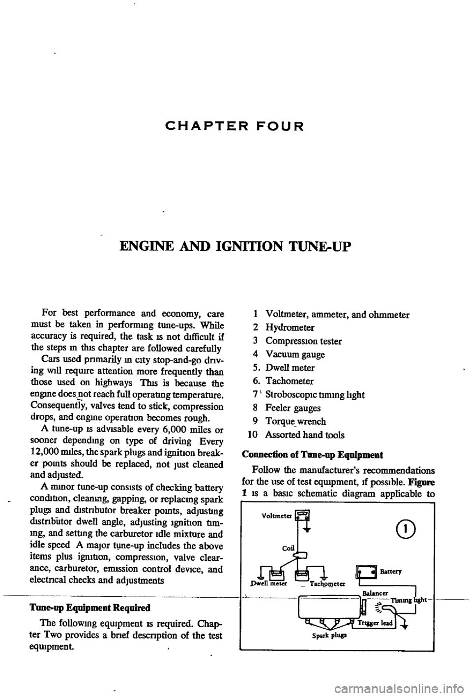
Figme
1
IS
a
basiC
schematic
diagram
applicable
to
CD
10
Battery
I
TIm1Illbght
T
8Ier
spa
k
plup
Page 26 of 252
ENGINE
AND
IGNITION
TUNE
UP
21
many
types
of
test
eqUipment
and
may
be
used
as
a
gUide
If
the
manufacturer
s
mstructioQs
are
not
aVailable
Connections
shown
in
Figure
1
are
as
follows
1
Voltmeter
a
PosItive
lead
to
resistor
side
of
COli
b
Negative
1
ead
to
ground
2
Tlmmg
Light
a
PosItive
lead
to
posItive
battery
termmal
b
Tngger
lead
to
number
1
spark
plug
c
Negative
lead
to
ground
3
Tachometer
a
PosItive
lead
to
dlstnbutor
Side
of
coil
b
Negative
lead
to
ground
4
Dwell
Meter
a
PosItive
lead
to
dlstnbutor
Side
of
COlI
b
Negative
lead
to
ground
BAlTERY
INSPECTION
AND
SERVICE
1
Check
the
level
of
the
electrolyte
m
battery
cells
If
necessary
replemsh
with
distilled
water
Do
not
overfill
2
Measure
the
speCific
gravity
of
the
battery
electrolyte
Refer
to
the
followmg
table
2
Use
the
proper
size
socket
and
wrench
to
remove
spark
plugs
from
the
cyhnder
head
Make
certam
that
the
gaskets
are
removed
from
the
spark
plug
holes
3
Wipe
off
the
msulator
With
a
clean
rag
to
remove
grease
and
dirt
4
Carefully
mspect
the
msulator
and
body
of
each
plug
for
signs
of
cracks
or
chips
Replace
If
faulty
5
Inspect
spark
plug
threads
and
electrodes
for
damage
or
excessive
wear
Replace
as
requrred
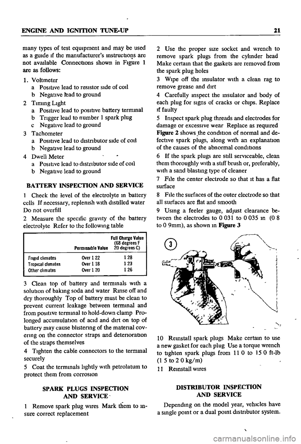
Figure
2
shows
the
cond1t
J
on
of
normal
and
de
fectIVe
spark
plugs
along
with
an
explanation
of
the
causes
of
the
abnormal
conditions
6
If
the
spark
plugs
are
still
serviceable
clean
them
thoroughly
With
a
stiff
brush
or
preferably
With
a
sand
blasting
type
of
cleaner
7
File
the
center
electrode
so
that
It
has
a
fiat
surface
8
File
the
surfaces
of
the
outer
electrode
so
that
all
surfaces
are
fiat
and
smooth
9
Usmg
a
feeler
gauge
adjust
clearance
be
tween
the
electrodes
to
0
031
to
0
035
m
0
8
to
0
9mm
as
shown
m
Figure
3
Full
Charge
Value
CD
68
degrees
F
PermiSSIble
Value
20
degrees
C
3
Frigid
chmates
Tropical
chmates
Other
climates
Over
1
22
Over
118
Over
1
20
128
123
126
3
Clean
top
of
battery
and
termmals
With
a
solutIOn
of
bakmg
soda
and
water
Rmse
off
and
dry
thoroughly
Top
of
battery
must
be
clean
to
prevent
current
leakage
between
termmal
and
from
pOSitive
termmal
to
hold
down
clamp
Pro
longed
accumulatIOn
of
aCid
and
dirt
on
top
of
battery
may
cause
blIstenng
of
the
matenal
cov
enng
on
the
connector
straps
and
detenoration
of
the
straps
themselves
4
Tighten
the
cable
connectors
to
the
termmal
securely
5
Coat
the
termmals
lIghtly
With
petrolatum
to
protect
them
from
corrosion
SPARK
PLUGS
INSPECTION
AND
SERVICE
1
Remove
spark
plug
WIres
Mark
them
to
fi
sure
correct
replacement
J
J
I
I
j
j
10
Remstall
spark
plugs
Make
certam
to
use
a
new
gasket
for
each
plug
Use
a
torque
wrench
to
tighten
spark
plugs
from
11
0
to
150
ft
lb
1
5
to
2
0
kg
m
11
Remstall
WIres
DISTRIBUTOR
INSPECTION
AND
SERVICE
Dependmg
on
the
model
year
velucles
have
a
smgle
pomt
or
a
dual
pomt
dlstnbutor
system
Page 27 of 252
22
CHAPTER
FOUR
CD
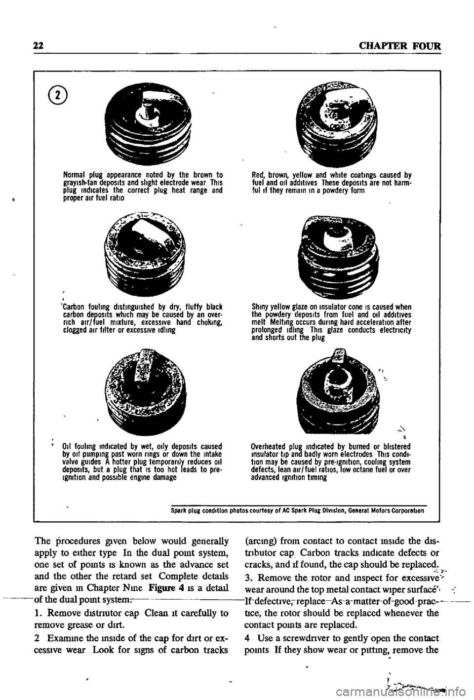
Normal
plug
appearance
noted
by
the
brown
to
graYish
tan
deposits
and
slight
electrode
wear
This
plug
rndlcates
the
correct
plug
heat
range
and
proper
air
fuel
ratio
f
j
l
Carbon
fouling
dlstrngUlshed
by
dry
fluffy
black
carbon
deposits
which
may
be
caused
by
an
over
nch
alr
fuel
mixture
excessIVe
hand
chokrng
clogged
air
filter
or
excessive
Idling
lJ
6
1
4i
Z
011
fouling
rndlcated
by
wet
OIly
depOSits
caused
by
011
pumprng
past
worn
rrngs
or
down
the
rntake
valve
gUides
A
hotter
plug
temporanly
reduces
011
depOSits
but
a
plug
that
IS
too
hot
leads
to
pre
IgmtlOn
and
possible
engrne
damage
Red
brown
yellow
and
white
coatrngs
caused
by
fuel
and
011
additives
These
depOSits
are
not
harm
ful
If
they
remarn
rn
a
powdery
form
C
I
Shrny
yellow
glaze
on
rnsulator
cone
IS
caused
when
the
powdery
depOSits
from
fuel
and
011
additives
melt
Meltrng
occurs
dunng
hard
acceleration
after
prolonged
Idling
This
glaze
conducts
electnclty
and
shorts
out
the
plug
Overheated
plug
rndlcated
by
burned
or
blistered
rnsulator
tip
and
badly
worn
electrodes
This
condl
bon
may
be
caused
by
pre
Igmtlon
cooling
system
defects
lean
air
fuel
ratiOS
low
octane
fuel
or
over
advanced
Igmbon
bmrng
Spark
plug
condition
photos
courtesy
of
At
Spark
Plug
DIvision
General
Motors
Corporation
The
procedures
given
below
would
generally
apply
to
eIther
type
In
the
dual
pomt
system
one
set
of
pomts
IS
known
as
the
advance
set
and
the
other
the
retard
set
Complete
details
are
given
m
Chapter
Nme
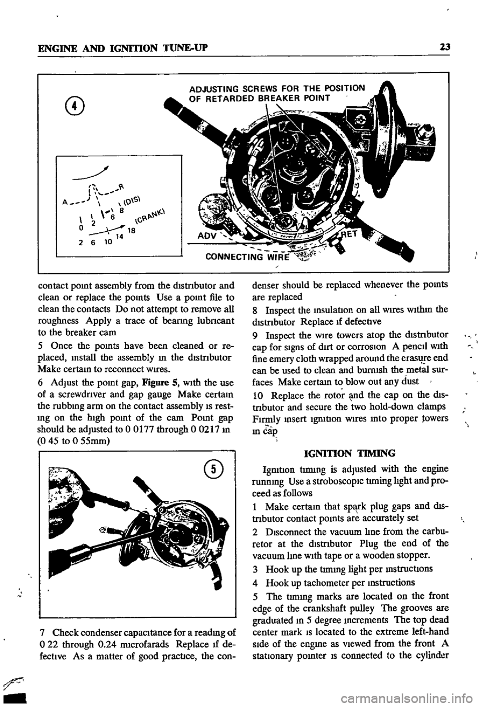
Figure
4
IS
a
detaIl
of
the
dual
pomt
system
1
Remove
dIStnutor
cap
Clean
It
carefully
to
remove
grease
or
dIrt
2
Examme
the
mSIde
of
the
cap
for
d1rt
or
ex
ceSSIve
wear
Look
for
SIgns
of
carbon
tracks
arcmg
from
contact
to
contact
mSIde
the
dIS
trIbutor
cap
Carbon
tracks
mdlcate
defects
or
cracks
and
If
found
the
cap
should
be
replaced
3
Remove
the
rotor
and
mspect
for
exceSSIve
wear
around
the
top
metal
contact
wiper
surface
If
defectlve
replace
As
a
matter
of
good
prac
nce
the
rotor
should
be
replaced
whenever
the
contact
pomts
are
replaced
4
Use
a
screwdriver
to
gently
open
the
contact
pomts
If
they
show
wear
or
plttmg
remove
the
I
7
r
Page 28 of 252
ENGINE
AND
IGNITION
TUNE
UP
23
CD
ADJUSTING
SCREWS
FOR
THE
POSITION
OF
RETARDED
BREAKER
POINT
r
A
O
S
8
6
C
0
18
2
6
10
14
contact
pomt
assembly
from
the
dIStnbutor
and
clean
or
replace
the
pomts
Use
a
pomt
file
to
clean
the
contacts
Do
not
attempt
to
remove
all
roughness
Apply
a
trace
of
beanng
lubncant
to
the
breaker
cam
5
Once
the
pomts
have
been
cleaned
or
re
placed
mstall
the
assembly
m
the
dlstnbutor
Make
certam
to
reconnect
wires
6
Adjust
the
pomt
gap
Figure
S
With
the
use
of
a
screwdnver
and
gap
gauge
Make
certaIn
the
rubbmg
arm
on
the
contact
assembly
IS
rest
mg
on
the
hIgh
pomt
of
the
carn
Pomt
gap
should
be
adjusted
to
0
0177
through
00217
m
0
45
to
0
55mm
CD
7
Check
condenser
capacItance
for
a
readmg
of
o
22
through
0
24
mIcrofarads
Replace
If
de
fectIve
As
a
matter
of
good
practIce
the
con
r
denser
should
be
replaced
whenever
the
pomts
are
replaced
8
Inspect
the
InSulatIon
on
all
WIres
WIthIn
the
dIStributor
Replace
If
defectIve
9
Inspect
the
WIre
towers
atop
the
dIStnbutor
cap
for
SignS
of
dIrt
or
corrosIOn
A
pencIl
wIth
fine
emery
cloth
wrapped
around
the
erasl
e
end
can
be
used
to
clean
and
burnISh
the
metal
sur
faces
Make
certam
to
blowout
any
dust
10
Replace
the
rotor
md
the
cap
on
the
dIs
tnbutor
and
secure
the
two
hold
down
clamps
FI
ly
msert
IgrntIon
WIres
mto
proper
towers
ill
cap
IGNITION
TIMING
IgmtIon
tIDlIDg
is
adjusted
with
the
engine
runnmg
Use
a
strobOSCOpIC
timing
hght
and
pro
ceed
as
follows
1
Make
certam
that
spl
l
k
plug
gaps
and
dIs
tnbutor
contact
pomts
are
accurately
set
2
DISconnect
the
vacuum
hne
from
the
carbu
retor
at
the
dIstrIbutor
Plug
the
end
of
the
vacuum
hne
wIth
tape
or
a
wooden
stopper
3
Hook
up
the
trmmg
light
per
mstructIons
4
Hook
up
tachometer
per
mstructions
5
The
tImmg
marles
are
located
on
the
front
edge
of
the
crankshaft
pulley
The
grooves
are
graduated
m
5
degree
mcrements
The
top
dead
center
mark
S
located
to
the
extreme
left
hand
sIde
of
the
engme
as
vIewed
from
the
front
A
statIOnary
pomter
S
connected
to
the
cylinder
Page 29 of 252
P
r
OVll
t
ate
I
l
h
l
JlA
ye
I
o
ctg
fI
O
0
I
d
1e
d
c
Ji
uo
JJ
cb
c
s
rlr
I
l
4
c
1
2
24
CHAPTER
FOUR
block
and
should
be
used
as
the
reference
point
m
II
1akmg
adjustments
6
With
a
piece
of
white
chalk
mark
a
hne
down
the
center
of
the
pomter
and
mark
the
timing
groove
on
the
crankshaft
pulley
which
IS
to
be
used
m
tImmg
the
engine
SpecIficatIon
for
tun
ing
reqUIres
trlhmg
at
10
degrees
before
top
dead
center
wluch
would
be
the
fourth
mark
from
the
left
end
of
the
row
of
marks
7
Loosen
the
hold
down
bolt
at
the
base
of
the
dlstnbutor
8
Locate
the
slow
speed
1
Ile
adjustIng
screw
on
the
carburetor
so
that
Ile
speed
can
be
adjusted
whIle
runnmg
Also
locate
throttle
adJustmg
screw
9
Start
engme
and
adjust
speed
With
the
adJust
ing
screws
to
the
readmgs
below
Smgle
pomt
dIStributor
600
rpm
Dual
pomt
trlbutor
700
rpm
10
Alternate
adjustment
of
the
two
screws
untIl
the
smoothest
Idle
at
the
proper
speed
IS
achieved
11
Pomt
the
tlIrung
lIght
at
the
stationary
pomter
When
the
lIght
flashes
the
timmg
mark
n
the
crankshaft
pulley
should
hne
up
With
the
mark
on
the
stationary
pomter
If
It
does
not
exactly
Ime
up
rotate
the
dlstnbutor
gradually
untIl
the
marks
align
mdlcatlng
correct
timmg
12
Shut
off
the
engme
remove
the
tmung
lIght
and
tachometer
tighten
the
hold
down
bolt
on
the
dlStnbutor
and
connect
the
vacuum
advance
hne
to
the
tli
tnbutor
IGNITION
TIMING
IDLE
SPEED
IDLE
MIXTURE
DUAL
POINT
DISTRIBUTOR
ONLY
The
followmg
applies
to
velucles
With
dual
pomt
distributor
and
an
exhaust
emission
con
trol
deVice
If
these
procedures
are
followed
ha
ul
exhaust
emisSion
should
be
below
the
maximum
allowable
level
1
Locate
the
Idle
and
throttle
adJustmg
screws
on
the
carburetor
2
Warm
up
the
engine
thoroughly
3
Connect
tachometer
and
tmung
light
4
Set
the
Id
le
speed
at
700
rpm
With
the
Idle
adjust
screw
5
Adjust
IgnltJ
on
tuning
at
10
degrees
before
top
dead
center
6
Increase
the
speed
of
the
engme
to
2
000
rpm
With
the
accelerator
or
throttle
hnkage
and
hold
for
about
15
seconds
7
Return
to
Idle
for
one
mmute
8
Set
the
engme
to
best
Idle
at
750
rpm
770
rpm
for
automatJ
c
transIDlsslOn
With
the
Idle
and
throttle
adJustmg
screws
9
Re
uce
engme
speed
at
700
rpm
720
rpm
for
automatic
transmission
by
turnmg
the
Idle
adJustmg
screw
clockWise
for
a
leaner
IlliXture
10
Connect
a
wife
lead
between
the
advance
ami
retard
Side
tenrunals
See
Figure
4
Speed
should
drop
from
100
to
150
rpm
11
Check
IgIl1tIon
tmung
With
tImmg
light
It
should
now
be
at
top
d
ad
center
12
If
the
tlmmg
IS
nSJt
correct
stop
the
engme
and
adjust
the
retarded
breaker
pomt
13
Start
the
engme
and
reclieck
ili
tmung
If
l
incorrect
reset
the
retarded
breaker
pomt
until
it
IS
correct
Repeat
s
nece
s
14
Disconnect
the
wife
bet
reen
the
advance
and
retard
termmals
15
Recheck
tmung
It
should
be
10
degrees
before
top
dead
center
16
If
mcorrect
repeat
the
above
procedures
un
tIl
satIsfactory
17
T
he
Idle
speed
of
automatic
transnllsslOn
vehicles
should
be
about
575
rpm
With
the
gear
j
selector
m
the
dhve
poSltlon
c
t
DWELL
ANGLE
SETIING
1
Connect
the
dwell
angle
meter
2
PLoJust
dwell
angle
to
49
to
55
degrees
OMPRESSION
TEST
I
A
compressIOn
test
IS
performed
to
check
for
worn
piston
nngs
or
to
detect
the
cause
of
a
low
speed
miss
Before
undertaking
the
test
el
llmate
the
pOSSibility
of
sticky
valves
by
usmg
one
of
the
oil
additives
deSigned
for
the
purpose
With
valves
free
test
compressIOn
as
follows
1
Run
the
engme
for
15
to
20
mmutes
untIl
normal
operating
temperatures
are
obtained
2
Shut
off
engme
remove
arr
cleaner
and
Page 30 of 252
ENGINE
AND
IGNITION
TUNE
UP
4
25
block
the
throttle
and
choke
m
the
WIde
open
position
3
Remove
all
four
spark
plugs
4
Sequentially
press
a
compressIOn
test
gauge
mto
each
of
the
spark
plug
holes
and
crank
the
engme
for
at
least
four
strokes
Record
the
com
pressIOn
readmg
for
each
cylmder
Standard
compressIOn
readmg
IS
171
Ibs
m
12
0
kg
cm
Mmlmum
acceptable
readmg
IS
159
lbs
m
2
11
5
kg
cm
5
No
readmg
should
be
less
than
80
of
the
highest
cylmder
reading
ExceSSive
vanatiC
ns
between
cylmders
accompanied
by
low
speed
mlssmg
of
the
cyhnder
or
cylmders
that
read
low
usually
mdlcates
a
valve
not
properly
seat
mg
or
a
broken
piston
ring
Low
pressures
even
though
uniform
may
mdicate
worn
nngs
ThIS
IS
especlall
true
1f
ex
cessive
011
cQIlsumptlon
has
been
noticed
If
one
or
more
cylmders
read
low
or
uneven
inject
about
a
tablespoon
of
engine
ail
on
top
of
the
piston
of
that
cylinder
and
crank
the
engine
several
tlmes
noting
the
compressIOn
reading
If
compressIOn
has
nsen
the
piston
nngs
or
cylmders
are
worn
and
should
befserviced
If
compressIOn
has
not
unproved
after
addmg
oil
the
valves
are
Stlcking
or
are
not
seating
prop
erly
If
two
adjacent
cylmders
have
low
compres
sion
and
mjectmg
01
9es
not
increas
the
read
mg
the
head
gasket
between
the
cylmders
IS
probably
leaking
VALVE
CLEARANCE
ADJUSTMENT
Valve
adjustment
should
be
done
in
two
steps
first
With
the
engme
cold
and
then
at
operatmg
temperature
Refer
to
Figure
6
and
proceed
as
follows
1
Remove
arr
liter
2
Remove
rocker
arm
cover
Take
care
not
to
damage
the
gasket
3
Remove
the
spark
plugs
and
rotate
the
en
gine
unt1l
number
1
cylinder
IS
at
top
dead
center
o
l
the
compressIOn
stroke
This
can
be
de
tepnmed
w
hen
the
top
dead
center
mark
on
the
crankshaft
pulley
is
m
alignment
With
the
statIOnary
pomter
and
both
valves
for
number
1
cylmder
are
closed
I
4
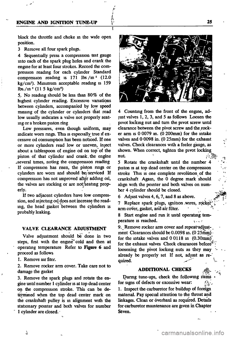
Counting
from
the
front
of
the
engme
ad
Just
valves
1
2
3
and
5
as
follows
Loosen
the
pivot
lockmg
nut
and
turn
the
pivot
screw
unt1l
clearance
between
the
pivot
screw
and
the
rock
er
ann
IS
0
0079
m
0
200mm
for
the
mtake
valves
and
0
0098
in
0
25mm
for
the
exhaust
valves
Check
clearances
With
a
feeler
gauge
as
shawn
When
correct
tlghten
the
pivot
locking
nut
l
1
5
Rotate
the
crankshaft
unt1l
the
number
4
pISton
IS
at
top
dead
center
an
the
compressIOn
stroke
This
IS
one
complete
revolution
of
the
crankshaft
Agam
the
0
degree
mark
should
align
With
the
pomter
and
both
valves
on
num
ber
4
cylinder
should
be
closed
6
Adjust
valves
4
6
7
and
8
as
above
i
I
7
Replace
spark
plugs
Ignition
WIres
r
ick
r
1
arm
cover
gasket
and
air
filter
8
Start
engine
and
run
it
unt1l
operating
tem
perature
IS
reached
9
Remove
rocker
ann
cover
and
repeava
iius
ment
Clearances
should
be
0
0098
m
0
25fumj
for
the
mtake
valves
and
00Il8
m
0
30mi
for
the
exhaust
valves
Check
clearances
before
loosening
the
pivot
lockmg
nuts
as
they
may
already
be
properly
set
If
not
adjust
as
re
quir
l
ADDmONAL
CHECKS
l
Qunng
tune
ups
check
the
followmg
Ite
far
SignS
of
defects
or
excessive
wear
I
i
1
Inspect
the
carburetor
for
buildup
of
foreign
matenal
Pay
Special
attention
to
the
throat
and
linkages
Clean
or
overhaul
as
required
Det8
1ls
for
carburetor
mamtenance
are
given
in
Chapter
seven