lock DATSUN 610 1969 Owner's Manual
[x] Cancel search | Manufacturer: DATSUN, Model Year: 1969, Model line: 610, Model: DATSUN 610 1969Pages: 171, PDF Size: 10.63 MB
Page 50 of 171
inter
lliJ
j
flDlJ
l
Jl
iO
n
cxB
L
of
lii
t
hl
9
q
6
15
1
r
8t
r
L
L
I
i
1
2
9
@
7
5I1
9
QlIf12
12J
J
7
ll
I
I
o
Q
1
Cylinder
2
Return
spring
3
Piston
4
Secondary
cup
5
Piston
cup
6
Supply
valve
seat
7
Supply
valve
stem
8
Supply
lIOlve
spring
9
Spring
seat
10
Va
ve
stem
stop
11
Stopper
gasket
12
Gasket
ring
13
Push
rod
14
Push
rod
ht
lld
15
Wdd
nut
16
Lock
nut
17
Piston
stopper
18
Stopper
ring
19
Boots
20
Oil
reservoir
21
Rese1l
Oir
band
22
Reservoir
cop
23
Cap
24
Pipe
seat
J
J
5
9
a
ID
1
Cylinder
2
Return
spring
C1
3
Piston
4
Spring
seat
5
Push
rod
6
Nut
7
Stopper
ring
8
Stopper
9
Dust
cover
10
on
reservoir
1
J
Reservoir
balld
12
Reservoir
cap
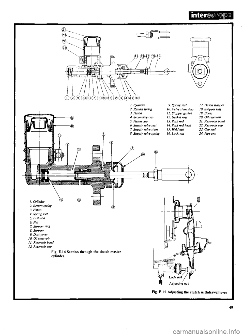
Fig
E
14
Section
through
the
clutch
master
cylinder
Adjusting
nut
Fig
E
l
S
Adjusting
the
clutch
withdrawal
lever
49
Page 52 of 171
Gearbox
GEARBOX
Removal
GEARBOX
Dismantling
GEARBOX
Inspection
and
Overhaul
GEARBOX
Assembling
THREE
SPEED
GEARBOX
GEARCHANGE
CONTROL
Removal
and
Adjusting
AUTOMATIC
TRANSMISSION
Gearchange
control
linkage
DESCRIPTION
Three
types
of
transmission
are
available
for
the
Datsun
models
covered
by
this
manual
Either
a
three
speed
gearbox
a
four
speed
gearbox
or
three
speed
automatic
transmission
can
be
fitted
The
three
and
four
speed
gearboxes
are
equipped
with
nchromesh
on
all
forward
gears
with
the
three
speed
gearbox
operated
by
a
steering
column
gearchange
system
and
the
four
speed
gearbox
by
a
floor
mounted
gear
lever
Two
types
of
synchromesh
are
used
in
the
four
speed
gearboxes
Either
Borg
Warner
or
Servo
types
may
be
fitted
The
gearboxes
differ
only
in
the
synchromesh
devices
whereby
the
baulk
rings
synchronize
the
coupling
sleeve
with
the
main
shaft
gear
on
the
Warner
gearbox
This
action
is
accomplished
by
a
synchrcrring
on
the
servo
gearbox
THREE
SPEED
GEARBOX
Removal
I
Jack
up
the
vehicle
and
support
it
on
stands
2
Disconnect
the
hand
brake
cable
at
the
equalizer
bracket
Slacken
the
two
exhaust
pipe
centre
clamps
and
turn
the
centre
section
of
the
exhaust
assembly
to
the
left
as
shown
in
Fig
F
2
3
Disconnect
the
propeller
shaft
from
the
rear
axle
drive
flange
by
removing
the
four
securing
bolts
Seal
off
the
gearbox
extension
housing
to
prevent
the
loss
of
oil
and
withdraw
the
shaft
to
the
rear
4
Disconnect
the
speedometer
drive
cable
from
the
adaptor
in
the
gearbox
extension
housing
Fig
F3
S
Disconnect
the
lower
shift
rods
from
the
shift
levers
Fig
F
4
and
remove
the
cross
shaft
assembly
from
the
gearbox
casing
Remove
the
clutch
slave
cylinder
from
the
clutch
housing
Fig
F
5
6
Support
the
engine
with
ajack
positioned
underneath
the
oil
sump
making
sure
that
the
jack
does
not
foul
the
drain
plug
A
block
of
wood
should
be
placed
between
the
sump
and
jack
to
avoid
damaging
the
sump
7
Remove
the
bolts
securing
the
rear
engine
mounting
to
the
crossmember
Position
ajack
under
the
gearbox
and
remove
the
bolts
attaching
the
crossmember
to
the
body
Lower
the
jack
under
the
engine
so
that
the
engine
is
tilted
to
the
rear
Remove
the
starter
motor
and
the
bolts
securing
the
clutch
housing
to
the
engine
Lower
the
jack
slowly
and
withdraw
the
gearbox
towards
the
rear
of
the
vehicle
THREE
SPEED
GEARBOX
Dismantling
Drain
the
gearbox
oil
Remove
the
dust
cover
release
the
retainer
spring
and
remove
the
withdrawal
lever
complete
with
release
bearing
from
the
clutch
housing
See
section
CLUTCH
Remove
the
gearbox
bottom
cover
the
speedometer
drive
pinion
assembly
and
the
rear
extension
housing
Take
out
the
cross
shaft
retaining
rings
and
unscrew
the
nuts
securing
the
operating
lever
lock
pins
Use
a
hammer
and
punch
to
drive
out
the
pins
and
withdraw
both
cross
shafts
Fig
F
6
Remove
the
fr
mt
cover
and
withdraw
the
counter
shaft
Lift
out
the
countersbaft
gear
cluster
together
with
the
needle
roller
bearings
and
spacers
Fig
F
7
Remove
the
reverse
idler
gear
shaft
lock
bolt
and
remove
the
shaft
and
the
idler
gear
Fig
F
B
Drive
out
the
pins
securing
the
selector
forks
to
the
selector
rods
Unscrew
the
interlock
plug
and
remove
the
detent
ball
and
spring
Fig
F
9
Remove
the
first
reverse
speed
and
second
third
speed
selector
rods
and
lift
out
the
selector
forks
Withdraw
the
main
shaft
assembly
and
the
drive
shaft
assembly
from
the
gearbox
See
Fig
F
1O
and
F
11
To
dismantle
the
mainshaft
release
the
circlip
from
the
front
of
the
mainshaft
as
shown
in
Fig
F
12
and
remove
the
second
and
third
speed
synchronizer
hub
and
second
speed
gearwheel
Fig
F
13
Remove
the
circlip
securing
the
speedo
meter
drive
gear
and
withdraw
the
gear
together
with
the
ball
and
spacer
Fig
F
14
Remove
the
mainshaft
bearing
using
a
press
Hold
the
rnainshaft
reverse
gear
and
tap
the
shaft
on
a
piece
of
wood
to
release
the
reverse
gear
assembly
together
with
the
first
speed
gearwheel
GEARBOX
Inspection
and
Overhaul
Oean
all
parts
thoroughly
and
examine
the
gearbox
case
and
extension
housing
for
cracks
If
the
joint
faces
are
burred
or
pitted
it
may
be
necessary
to
replace
the
units
if
repair
cannot
be
carried
out
satisfactorily
Remove
any
adhesive
which
remains
on
the
faces
The
rear
extension
housing
bush
should
be
renewed
if
worn
unevenly
Clean
the
bearings
and
dry
with
compressed
air
taking
care
that
the
bearings
do
not
spin
Turn
the
ball
bearings
to
make
sure
that
they
run
smoothly
and
without
play
Replace
the
needle
bearings
if
worn
or
damaged
in
any
way
It
is
advisable
to
renew
the
needle
roller
bearings
after
they
have
been
installed
for
a
considerable
period
as
it
is
difficult
51
Page 54 of 171

jiii
c
c
inteN
I
j
D
p
Fig
F
7
Removing
the
countershaft
gear
Fig
F
6
Removing
the
ero
shaft
tT
l
Fig
F
S
Removing
the
reverse
idler
gear
JO
Fig
F
9
Removing
the
interlock
plug
F
8
F
I
0
Withdrawing
the
mainshaft
gear
assembly
Fig
F
lI
Removing
the
main
drive
shaft
Fig
F
12
Removing
the
2nd
and
3rd
speed
syndlroniur
hub
circlup
f
Ii
ii
jjf
vr
O
Fig
F
13
Removins
the
2nd
and
3rd
speed
hub
and
2nd
speed
gearwheel
S3
Page 56 of 171
to
ascertain
the
amount
of
wear
that
has
taken
place
Check
the
teeth
of
the
gearwheels
and
the
machined
surfaces
for
signs
of
wear
scoring
pitting
and
burrs
Ensure
that
the
synchronizer
hubs
slide
freely
on
the
splines
of
the
main
shaft
with
minimum
clearance
Check
the
mainshaft
for
run
out
using
V
blocks
and
a
dial
gauge
as
shown
in
Fig
F
15
Renew
the
mainshaft
if
the
run
out
exceeds
0
15mm
0
0059
in
Check
the
synchronizer
rings
for
wear
and
renew
them
if
necessary
Place
the
rings
in
position
on
their
respective
gear
wheel
cones
and
check
the
gap
between
the
end
of
the
ring
and
the
front
face
of
the
teeth
Fig
F
16
The
correct
gap
should
be
within
1
2
1
6mm
0
047
0
063
in
Renew
the
synchronizer
ring
if
the
gap
is
less
than
0
8mm
0
0315
in
Place
the
selector
rods
on
a
flat
surface
and
check
them
for
traightness
Renew
any
rod
which
is
bent
Renew
the
locking
pins
and
interlock
balls
if
they
are
worn
or
damaged
The
standard
clearance
between
the
selector
forks
and
operating
sleeve
groove
is
0
15
0
30mm
0
006
0
012
in
Make
sure
that
the
oil
seals
are
satisfactory
and
discard
the
O
rings
THREE
SPEED
GEARBOX
Assembly
Press
the
main
drive
gear
bearing
onto
the
main
drive
shaft
and
fit
the
spacer
Select
a
snap
ring
of
suitable
thickness
so
that
all
play
is
eliminated
between
the
bearing
and
snap
ring
Seven
sizes
of
snap
rings
are
available
and
vary
in
thickness
from
1
52mm
0
0598
in
to
1
89mm
0
0747in
The
synchromesh
unit
consists
of
a
coupling
sleeve
baulk
ring
spring
synchronizer
hub
and
insert
When
assembling
the
unit
make
sure
that
the
correct
insert
pressure
springs
are
fitted
to
the
relevant
speed
unit
The
first
reverse
gear
synchronizer
should
be
fitted
with
the
three
coil
spring
type
and
the
second
third
gear
synchronizer
with
the
two
expanding
springs
To
assemble
the
fiI3t
speed
synchronizer
insert
the
sliding
insert
snap
ring
onto
the
synchronizer
hub
as
shown
in
Fig
F
17
Fit
the
sliding
inserts
Fig
F
18
and
the
synchronizer
springs
on
the
synchronizer
hub
and
assemble
the
synchronizer
hub
complete
with
inserts
into
the
coupling
sleeve
Fig
F
19
Assemble
the
second
third
gear
synchronizer
hub
and
coupling
sleeve
making
sure
that
the
sleeve
slides
freely
on
the
hub
splines
Fit
the
three
shifting
inserts
and
install
a
spring
ring
on
each
side
of
the
hub
Fig
F
20
To
assemble
the
mainshaft
start
from
the
front
end
of
the
shaft
and
slide
the
second
speed
gearwheel
on
to
the
shaft
with
the
tapered
cone
facing
forwards
Install
the
baulk
ring
on
the
gearwheel
and
place
the
second
third
speed
synchronizer
assembly
on
the
front
end
of
the
shaft
and
retain
it
with
a
snap
ring
which
will
give
an
end
play
of
0
05
0
25
mm
0
002
0
009
in
Snap
rings
are
available
in
five
sizes
from
1
60
1
80
mm
0
063
0
071
in
Fit
the
first
speed
gear
and
baulk
ring
on
the
rear
of
the
shaft
so
that
the
tapered
cone
faces
to
the
rear
Assemble
the
first
speed
synchronizer
and
reverse
gear
on
the
shaft
Fit
the
spacer
and
press
the
mainshaft
bearing
complete
with
retainer
onto
the
shaft
Install
the
spacer
ball
and
speedometer
drive
pinion
Select
a
snap
ring
which
will
give
an
end
float
of
0
05
0
22mm
0
002
0
009
in
on
the
mainshaft
first
gear
Snap
rings
are
available
in
eight
thicknesses
from
1
30mrn
0
0512
in
to
1
70mm
0
0669
in
Secure
the
drive
gear
with
the
selected
snap
ring
and
check
the
end
float
of
the
gearwheels
as
shown
in
Fig
F
21
The
correct
end
float
should
be
as
follows
I
st
speed
gearwheel
0
2
o
3mm
0
008
0
012
in
0
2
0
3mm
0
008
0
012
in
2nd
speed
gearwheel
Fit
the
main
drive
gear
and
mainshaft
assembly
into
the
gearbox
casing
Fit
the
selector
rods
and
forks
as
follows
Turn
the
gearbox
casing
so
that
the
detent
ball
hole
is
uppermost
and
insert
the
spring
and
ball
in
the
bottom
of
the
hole
Hold
the
ball
witb
a
dummy
shaft
and
install
tbe
first
reverse
selector
fork
and
rod
pushing
the
dummy
shaft
out
of
position
Insert
the
interlocking
plunger
and
fit
the
second
third
speed
selector
fork
and
rod
Insert
the
steel
ball
and
spring
and
refit
the
interlocking
plug
after
coating
the
threads
of
the
plug
with
sealing
compound
See
Fig
F
22
Secure
the
selector
forks
to
the
rods
by
inserting
the
retaining
pins
Fit
the
reverse
idler
gear
and
shaft
and
secure
the
shaft
with
the
lock
bolt
and
plate
Insert
the
counter
gear
cluster
and
shaft
using
a
suitable
thrust
washer
to
obtain
an
end
float
of
0
04
0
12
mm
0
0016
0
0047
in
Thrust
washers
are
available
in
five
sizes
from
3
85
4
05
mm
0
1516
0
1594
in
thickness
in
increments
of
0
05
mm
0
002
in
Fit
the
cross
shafts
1
in
Fig
F
23
the
thrust
washers
2
and
the
operating
levers
3
Secure
the
cross
shafts
with
the
retaining
rings
5
and
lock
the
operating
levers
to
the
shafts
with
the
pins
4
Locate
the
rear
extension
housing
on
the
gearbox
case
and
tighten
the
bolts
to
a
torque
reading
of
2
8
4
4
kgm
20
32
Ib
ft
Insert
the
speedometer
drive
pinion
and
retain
it
with
the
set
bolt
and
lock
plate
Check
the
backlash
of
all
the
gears
using
a
dial
gauge
as
shown
in
Fig
F
24
The
backlash
should
be
between
0
05
0
20
mm
0
002
0
008
in
Fit
the
gearbox
front
cover
and
tighten
the
fixing
bolts
to
a
torque
reading
of
1
I
1
7
kgm
8
0
12
3
lb
ft
taking
care
not
to
damage
the
oil
seal
Fit
the
clutch
release
bearing
and
with
drawallever
Fig
F
25
Replace
the
bottom
cover
and
tighten
the
bolts
to
a
torque
reading
of
1
I
1
7
kgm
8
0
12
31b
ft
THREE
SPEED
GEARBOX
Installation
Installation
of
the
gearbox
is
a
reversal
of
the
removal
procedure
noting
the
following
points
Fit
the
gearbox
with
I
7
litre
0
45
US
gall
0
37
Imp
gall
of
MP
90
gear
oil
Adjust
the
clutch
slave
cylinder
push
rod
as
described
in
the
section
CLUTCH
to
provide
a
free
play
of
2
2
mm
0
087in
at
the
withdrawal
lever
55
Page 57 of 171

inter
iillu@U
Fig
F
20
Filting
the
spring
rings
Fig
F
21
Olecking
the
end
float
of
lhe
gearwheels
Fig
F
22
The
interlock
mechanism
c
Fig
F
23
Installing
the
cross
shaft
1
crossshil
t
2
l
hnut
washers
3
OperatirJ8levm
4
Lock
pim
5
Retaining
rings
Fig
F
24
Ole
king
the
gear
backlash
hk
rmJ
t
0
o
y
9
Ll
7
1
l
i
A
I
f
0
Fig
F
25
Withdrawal
lever
and
reIe
e
bearing
Fig
F
26
View
of
the
four
speed
gearbox
with
bottom
cover
removed
II
56
Page 58 of 171
FOUR
SPEED
GEARBOX
Removal
and
Installation
The
removal
and
installation
procedures
for
the
four
speed
gearbox
are
similar
to
those
previously
described
for
the
three
speed
gearbox
However
the
floor
mounted
gear
lever
must
be
removed
from
the
controllevef
bracket
in
addition
to
the
operations
already
detailed
FOUR
SPEED
GEARBOX
Dismantling
Drain
the
oil
from
the
gearbox
Remove
the
dust
coveT
and
release
the
spring
securing
the
clutch
withdrawal
lever
Remove
the
withdrawal
lever
and
release
bearing
from
the
clutch
housing
as
described
in
the
section
CLurCH
Remove
the
clevis
pin
securing
the
striking
rod
to
the
control
lever
Remove
the
speedometer
drive
pinion
assembly
and
with
draw
the
rear
extension
housing
Disengage
the
striking
rod
from
the
selector
rod
gates
Remove
the
gearbox
covers
See
Figs
F
26
and
F
27
Unscrew
the
three
detent
ball
plugs
and
remove
the
spriags
and
detent
balls
Drive
out
the
pins
securing
the
selector
forks
to
the
rods
and
withdraw
the
forks
and
rods
Lock
the
main
shaft
by
moving
the
first
second
and
third
fourth
coupling
sleeve
into
gear
at
the
same
time
and
release
the
ffiainshaft
nut
Remove
the
countershaft
and
the
gear
cluster
together
with
the
two
needle
roller
bearings
and
spacers
Remove
the
snap
ring
holding
the
revep
e
idler
gear
and
withdraw
the
reverse
idler
gears
and
shaft
Fig
F
28
Take
off
the
bolts
securing
the
mainshaft
bearing
retainer
to
the
gearbox
case
Fig
F
29
Withdraw
the
mainshaft
assembly
Fig
F
30
and
the
main
drive
shaft
The
mainshaft
can
be
dismantled
in
the
following
manner
Release
the
third
fourth
synchronizer
unit
snap
ring
and
with
draw
the
hub
complete
with
coupling
sleeve
Remove
the
third
speed
gearwheel
and
the
needle
roller
bearing
from
the
main
shaft
Take
off
the
mainshaft
nut
and
locking
plate
Remove
the
speedometer
drive
gear
with
the
retaining
ball
Withdraw
the
mainshaft
reverse
gear
and
the
hub
Press
off
the
mainshaft
bearing
complete
with
the
bearing
retainer
Remove
the
thrust
washer
and
the
first
speed
gear
together
with
the
needle
roller
bearing
taking
care
not
to
lose
the
small
baU
used
to
locate
the
thrust
washer
Slide
off
the
first
speed
gearwheel
bush
Withdraw
the
first
second
synchronizer
and
hub
Remove
the
second
speed
gearwheel
and
needle
roller
bearing
FOUR
SPEED
GEARBOX
Installation
Refer
to
the
instructions
given
for
the
three
speed
gearbox
and
to
Technical
Data
for
the
specifications
applicable
to
the
different
gearboxes
FOUR
SPEED
GEARBOX
Assembly
Assembly
of
the
gearbox
is
similar
to
the
procedures
previously
described
for
the
three
speed
gearbox
with
the
following
exceptions
When
assembling
the
main
drive
gear
bearing
on
the
shaft
insiall
the
spacer
and
select
a
new
snap
ring
to
eliminate
all
end
float
between
bearing
and
snap
ring
Snap
rings
are
available
in
five
thicknesses
from
1
52
1
77mm
0
06
0
07
in
The
assembly
procedures
for
the
Warner
type
synchronizers
are
similar
to
the
instructions
previously
described
for
the
three
speed
gearbox
Refer
to
THREE
SPEED
GEARBOX
Assembly
for
further
details
To
assemble
the
Servo
F4C63
type
synchronizers
proceed
as
follows
Place
the
gear
on
a
clean
flat
surface
and
install
the
synchronizer
ring
on
the
inner
side
of
theclutch
gear
Fit
the
thrust
block
into
place
as
shown
in
Fig
F
31
Place
the
anchor
block
and
brake
band
into
position
and
fit
the
circlip
into
the
groove
in
the
gear
to
secure
the
synchromesh
assembly
When
assembling
the
mainshaft
select
a
snap
ring
which
will
give
an
end
float
between
0
05
0
15
mm
0
002
0
006in
to
the
third
speed
gearwheel
Snap
rings
are
available
in
five
sizes
from
1
40
mm
0
0551
in
to
1
60
mm
0
0630
in
thick
ness
Tighten
the
locknut
at
the
rear
of
the
mainshaft
to
a
torque
reading
of
7
1
kgm
51
87Ib
ft
Assemble
the
reverse
idler
gear
as
shown
in
Fig
F
32
The
reverse
idler
driven
gear
3
should
be
placed
on
the
end
of
the
reverse
shaft
1
with
the
longest
spline
and
retained
with
a
suitable
snap
ring
2
Install
the
reverse
shaft
and
gear
assembly
into
the
gearbox
case
from
the
rear
with
the
thrust
washer
4
between
the
gear
and
the
case
Fit
the
thrust
washer
5
and
idler
gear
6
18
teeth
and
secure
with
a
suitable
snap
ring
2
The
end
float
of
the
gear
should
be
checked
and
adjusted
to
0
1
O
3mm
0
004
0
012
in
by
selecting
a
suitable
snap
ring
2
Five
thicknesses
of
snap
rings
are
available
from
I
lmm
0
043in
to
1
5mm
0
06in
See
Technical
Data
for
F4W63
and
F4C63
gearboxes
Adjust
the
counter
gear
end
float
to
0
05
0
15
mm
0
002
0
006in
by
selecting
a
thrust
washer
of
the
required
thickness
Thrust
washers
are
available
in
five
thicknesses
from
2
40
2
60
mm
0
094
0
102
in
When
assembling
the
selector
mechanisms
Fig
F
33
fit
the
first
second
selector
forks
I
and
the
third
fourth
selector
forks
2
onto
the
coupling
sleeves
and
insert
the
first
second
fork
rod
3
Fit
an
interlock
plunger
4
and
the
third
fourth
speed
selector
rod
5
Do
not
forget
the
interlock
pin
7
A
section
through
the
selector
and
interlock
mechanism
is
given
in
Fig
F
34
Install
an
interlock
plunger
6
and
assemble
the
reverse
selector
fork
8
and
fork
rod
9
Secure
the
selector
forks
to
the
rods
with
the
retaining
pins
10
Place
a
check
ball
and
spring
into
each
of
the
holes
and
screw
the
plug
down
to
a
torque
reading
of
1
7
2
1
Jegm
12
3
15
2
Ib
ft
after
coating
the
threads
with
sealing
com
pound
Install
the
rear
extension
housing
engaging
the
striking
rod
with
the
fork
rod
gates
and
tighten
the
housing
bolts
to
a
torque
reading
of
1
6
2
5
kgm
12
18Ib
ft
Fit
the
front
and
bottom
covers
and
tighten
the
bolts
to
a
torque
reading
of
1
1
1
8
kgm
8
13Ib
ft
57
Page 59 of 171

inter
lli
r@
ig
F
28
Re
oving
the
reverse
idler
gear
q
F
8
F
27
View
of
the
four
speed
gearbox
with
front
cover
removed
F
8
F
29
Removing
the
mainshaft
bearing
retainer
Fig
F
30
Withdrawing
the
mainshaft
assembly
CD
1ib
1
@
II
c
I
@
d
I
Q
n
j2
JJ
I
0
6
r
7
1
L
l
Hv
9
1l
ij07
u
1
1
v
1
ISland
2nd
selector
fork
5
Fork
rod
2
3rd
and
4th
selector
fork
6
Inter
ock
phmgtr
3
Fork
rod
7
Intulock
pin
4
Interlock
plunger
8
Revene
selLetor
fork
9
Fori
rod
10
Retaining
pin
Fig
F
33
Assembly
of
the
selector
forks
1
17uu
t
block
2
md
bruke
3
Synchro
rint
4
Anchor
block
5
Circlip
6
Band
b
ke
r
1
R
nt
shaft
SntJpring
3
R
idler
driving
geor
UT
4
Thrust
washer
5
1
hnat
washer
6
Idlergeor
18T
Fig
F
32
Reverse
idler
gear
F
8
F
31
Syncbromesh
assembly
3rd
4th
Rod
Fig
F
36
Removing
the
steering
wheel
Fig
F
34
Section
tIuough
the
gearbox
showing
the
inlerlock
mechanism
58
Page 60 of 171
THREE
SPEED
GEARBOX
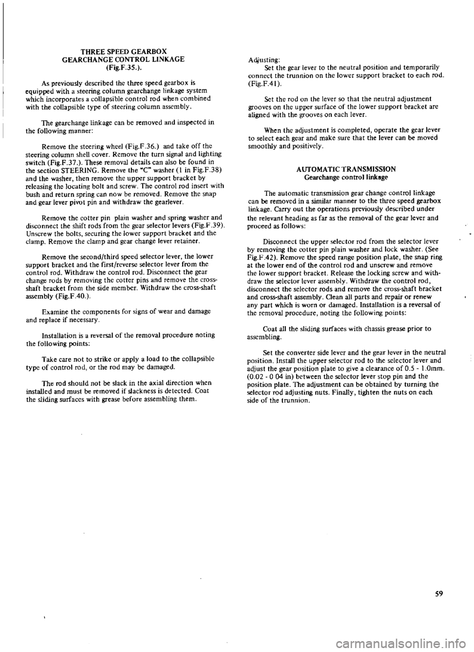
GEARCHANGE
CONTROL
LINKAGE
Fig
F
35
As
previously
described
the
three
speed
gearbox
is
equipped
with
a
steering
column
gearchange
linkage
system
which
incorporates
a
collapsible
control
rod
when
combined
with
the
collapsible
type
of
steering
column
assembly
The
gearchange
linkage
can
be
removed
and
inspected
in
the
following
manner
Remove
the
steering
wheel
Fig
F
36
and
take
off
the
steering
column
shell
cover
Remove
the
turn
signal
and
lighting
switch
Fig
F
37
These
removal
details
can
also
be
found
in
the
section
STEERING
Remove
the
C
washer
I
in
Fig
F
38
and
the
washer
then
remove
the
upper
support
bracket
by
releasing
the
locating
bolt
and
screw
The
control
rod
insert
with
bush
and
return
spring
can
now
be
removed
Remove
the
snap
and
gear
lever
pivot
pin
and
withdraw
the
gearlever
Remove
the
cotter
pin
plain
washer
and
spring
washer
and
disconnect
the
shift
rods
from
the
gear
selector
levers
Fig
F
39
Unscrew
the
bolts
securing
the
lower
support
bracket
and
the
clamp
Remove
the
clamp
and
gear
change
lever
retainer
Remove
the
second
third
speed
selector
lever
the
lower
support
bracket
and
the
first
reverse
selector
lever
from
the
control
rod
Withdraw
the
control
rod
Disconnect
the
gear
change
rods
by
removing
the
cotter
pins
and
remove
the
cross
shaft
bracket
from
the
side
member
Withdraw
the
cross
shaft
assembly
Fig
F
40
Examine
the
components
for
signs
of
wear
and
damage
and
replace
if
necessary
Installation
is
a
reversal
of
the
removal
procedure
noting
the
following
points
Take
care
not
to
strike
or
apply
a
load
to
the
collapsible
type
of
control
rod
or
the
rod
may
be
damaged
The
rod
should
not
be
slack
in
the
axial
direction
when
installed
and
must
be
removed
if
slackness
is
detected
Coat
the
sliding
surfaces
with
grease
before
assembling
them
Acijusting
Set
the
gear
lever
to
the
neutral
position
and
temporarily
connect
the
trunnion
on
the
lower
support
bracket
to
each
rod
Fig
F41
Set
the
rod
on
the
lever
so
that
the
neutral
adjustment
grooves
on
the
upper
surface
of
the
lower
support
bracket
are
aligned
with
the
grooves
on
each
lever
When
the
adjustment
is
completed
operate
the
gear
lever
to
select
each
gear
and
make
sure
that
the
lever
can
be
moved
smoothly
and
positively
AUTOMATIC
TRANSMISSION
Gearchange
control
linkage
The
automatic
transmission
gear
change
control
linkage
can
be
removed
in
a
similar
manner
to
the
three
speed
gearbox
linkage
Carry
out
the
operations
previously
described
under
the
relevant
heading
as
far
as
the
removal
of
the
gear
lever
and
proceed
as
follows
Disconnect
the
upper
selector
rod
from
the
selector
lever
by
removing
the
cotter
pin
plain
washer
and
lock
washer
See
Fig
F
42
Remove
the
speed
range
position
plate
the
snap
ring
at
the
lower
end
of
the
control
rod
and
unscrew
and
remove
the
lower
support
bracket
Release
the
locking
screw
and
with
draw
the
selector
lever
assembly
Withdraw
the
control
rod
disconnect
the
selector
rods
and
remove
the
cross
shaft
bracket
and
cross
shaft
assembly
Clean
all
parts
and
repair
or
renew
any
part
which
is
worn
or
damaged
Installation
is
a
reversal
of
the
removal
procedure
noting
the
following
points
Coat
all
the
sliding
surfaces
with
chassis
grease
prior
to
assembling
Set
the
converter
side
lever
and
the
gear
lever
in
the
neutral
position
Install
the
upper
selector
rod
to
the
selector
lever
and
adjust
the
gear
position
plate
to
give
a
clearance
of
0
5
I
Omm
0
02
0
04
in
between
the
selector
lever
stop
pin
and
the
position
plate
The
adjustment
can
be
obtained
by
turning
the
selector
rod
adjusting
nuts
Finally
tighten
the
nuts
on
each
side
of
the
trunnion
S9
Page 63 of 171

inter
E
lill
j
lll
jIl
1
3
I
i
1r
I
An
t
1
ll
1
11
5
85
1
Sleeve
voke
arsembh
Bearillg
race
assembh
Jvumal
asst
mb
r
4
Snap
ring
5
Prope
ier
shaft
tube
assl
mblv
6
flan
oke
2
O
L
l
OIlU
39
I
JII
I
I
i
i
3
1
378
@
Fig
G
I
Section
through
the
propeller
shaft
Unit
mm
in
@
@
j
c
@
I
I
i
@
@
@
J
q
cJi
y
j
rID
@
62
Fig
G
2
Section
through
the
differential
carrier
1
Supply
rrwlti
purpose
gTet1M
to
oil
seal
lip
when
ass
mb1ing
Pinion
bearing
adjusting
lWSher
Adjust
pinion
ber
uing
X
eload
by
selecting
2
and
3
Pinio
bearing
adjusting
spacer
4
PInion
height
adiustinx
MUS1m
5
Lock
strap
6
Ring
gear
bolts
T
7
0
to
8
0
kgm
50
6
ro
578
bIt
TIghten
by
tapping
bolt
head
with
Jj41b3
hamTMr
7
Lock
pin
8
Rear
cover
9
Ring
gmr
10
Diff
mounting
member
1
J
Bolt
diff
to
diff
mounting
member
T
6
0
to
8
0kKm
43
4
0
7
8
b
ft
12
ShIlf
pinion
m1te
13
Thnl
lWlJIJer
14
Pinion
mate
15
17vust
washer
Adjust
the
backla
h
in
pinion
mate
and
ide
gear
or
the
clearance
betwun
the
differential
ctlSI
and
the
rear
fact
ofridt
gror
to
0
1
to
0
2
mm
0
0039
0
0
0079
bv
16
16
Side
ar
17
BoltsideflilngeT
1
9to
6kgm
13
710
18
8Ib
f
18
Oil
tal
Supply
chassi
grea
e
to
oil
seal
lip
Vtlhen
autmbling
19
Side
flange
20
Side
retainer
21
Bolt
side
retainer
T
0
9
to
1
2
kgm
6
5
to
8
71b
22
ring
23
Side
bearing
24
Diff
Gear
case
25
Pinion
rear
bearing
26
Dril
e
pinion
27
Pinion
front
bearing
28
Spacer
front
pilot
beaTing
29
Front
pilot
bearing
30
Oil
seal
3J
CompanionfliInge
32
Dri
pinion
nut
T
17
to
20
Jwn
122
9
0144
6Ib
fI
Page 66 of 171
Check
the
run
out
at
the
ceac
of
the
crownwheel
if
the
back
lash
or
tooth
contact
pattern
is
incorrect
The
run
out
should
not
exceed
0
08mm
0
003
in
Measure
the
turning
torque
of
the
drive
pinion
which
should
be
within
7
IOkg
cm
6
9Ib
in
Shims
and
adjusting
washers
must
be
changed
if
the
tooth
contact
pattern
and
backlash
is
incorrect
the
necessary
details
for
these
operations
can
be
found
towacds
the
end
of
this
section
under
the
heading
TOOTH
CONTACT
PATTERN
To
dismantle
the
differential
remove
the
flange
clamp
bolt
and
extract
the
side
flange
as
shown
in
Fig
GA
using
the
special
stand
ST
33730000
and
sliding
hammec
ST
36230000
Remove
the
bearing
caps
with
a
suitable
puller
as
shown
in
Fig
G
5
Remove
the
left
hand
cap
first
followed
by
the
right
hand
cap
The
caps
should
be
marked
to
ensure
that
they
are
refitted
in
their
original
positions
Withdraw
the
differential
cage
from
the
carrier
Fig
G
6
Slacken
the
drive
pinion
and
hold
the
flange
with
a
suitable
wrench
as
shown
in
Fig
G
7
Withdraw
the
flange
with
a
standard
puller
Press
the
drive
pinion
out
of
the
differential
carrier
together
with
the
rear
bearing
inner
races
the
spacers
and
the
shims
Place
a
press
plate
between
the
drive
pinion
head
and
rear
bearing
and
press
out
the
pinion
shaft
The
inner
races
need
not
be
removed
if
the
tooth
contact
pattern
is
correct
and
the
crownwheel
drive
pinion
carrier
rear
bearing
and
shims
etc
are
to
be
re
used
The
front
and
rear
outer
races
of
the
pinion
bearings
can
be
removed
with
the
special
tool
ST
30610000
or
with
a
suitable
drift
To
dismantle
the
differential
cage
remove
the
right
hand
bearing
cone
as
shown
in
Fig
G
8
The
special
puller
ST
3306
0000
and
adaptor
ST
33052000
should
be
used
for
this
pur
pose
taking
care
not
to
damage
the
edge
of
the
bearing
innec
race
Flatten
the
lock
straps
slacken
the
crownwheel
bolts
in
a
diagonal
pattern
and
remove
the
crownwheeL
Remove
the
left
hand
bearing
cone
in
a
similar
manner
to
the
right
hand
bearing
cone
Make
sure
that
the
parts
do
not
become
mixed
and
can
be
assembled
in
their
original
positions
Punch
out
the
differential
shaft
lock
pin
from
the
crownwheel
side
using
a
suitable
drift
Great
care
must
be
taken
when
carrying
out
this
operation
as
the
pin
is
caulked
into
the
hole
in
the
differential
cage
Remove
the
shaft
the
differential
pinion
gears
and
the
side
gears
and
thrust
washers
Separate
the
left
and
right
hand
gears
and
washers
so
that
they
can
be
reassembled
in
their
original
positions
Replacing
oil
seals
with
the
differential
installed
The
oil
seals
can
be
replaced
if
necessary
with
the
differ
ential
fitted
to
the
vehicle
Front
oil
seal
Drain
the
oil
from
the
differential
unit
and
jack
up
the
vehicle
at
the
rear
Remove
the
propeller
shaft
from
the
differential
flange
Disconnect
the
handbrake
left
hand
rear
cable
Slacken
and
remove
the
drive
pinion
nuts
whilst
holding
the
drive
flange
with
a
suitable
wrench
or
special
tool
ST
31530000
Withdraw
the
drive
flange
with
a
conventional
two
l
arm
puller
as
shown
in
Fig
G
9
Use
the
oil
seal
puller
ST
33290000
to
withdraw
the
oil
seal
from
the
retainer
Replace
the
oil
seal
using
a
suitable
drift
or
special
tool
ST
33270000
Fill
the
oil
seal
lips
with
grease
when
installing
Fit
the
oil
seal
retainer
and
replace
the
various
parts
in
reverse
order
to
the
removal
procedure
Side
oil
seal
Detach
the
drive
shaft
from
the
side
flange
of
the
differ
ential
carrier
Extract
the
side
flange
with
the
slide
hammer
ST
36230000
and
adaptor
ST
33730000
as
shown
in
Fig
G
lO
Remove
and
replace
the
oil
seal
in
a
similar
manner
to
that
previously
described
for
the
front
oil
seal
taking
care
to
apply
grease
between
the
oil
seal
lips
DIFFERENTIAL
Inspection
Clean
the
parts
thoroughly
and
inspect
them
for
signs
of
wear
or
damage
Check
the
gear
teeth
for
scores
cracks
or
excessive
wear
Check
the
tooth
contact
pattern
of
the
crownwheel
and
pinion
for
correct
meshing
depth
The
crownwheel
and
pinion
are
supplied
as
a
set
and
should
either
part
be
damaged
it
will
be
necessary
to
renew
the
complete
set
2
Check
the
pinion
shaft
and
gear
mating
faces
for
scores
or
wear
Inspect
the
inner
faces
of
the
side
gears
and
their
seating
faces
on
the
differential
cage
3
Any
small
defects
on
the
faces
of
the
thrust
washers
can
be
corrected
using
emery
cloth
The
thrust
washers
must
be
replaced
however
if
the
backlash
between
the
side
gear
and
pinion
exceeds
0
2mm
0
008
in
and
the
clearance
between
the
side
gear
and
thrust
washer
exceeds
O
3mm
0
012
in
Three
sizes
of
washers
are
available
and
the
thicknesses
are
detailed
in
Technical
Data
at
the
end
of
this
section
4
Measure
the
run
out
of
the
crownwheel
at
the
rear
with
a
dial
gauge
Replace
the
crownwheel
and
drive
pinion
as
a
set
if
the
run
out
exceeds
the
permissible
value
of
O
08mm
0
003
in
5
Examine
the
differential
carrier
and
cage
for
cracks
or
distortion
Renew
any
part
found
to
be
defective
It
is
advisable
to
renew
all
oil
seals
DIFFERENTIAL
Assembly
and
Adjustment
Assembly
is
a
reversal
of
the
removal
procedure
noting
the
following
points
Arrange
the
shims
and
washers
etc
in
their
correct
order
and
thoroughly
clean
the
surfaces
to
which
the
shims
washers
bearings
and
bearing
retainecs
are
to
be
installed
Differential
cage
Fit
the
differential
side
gear
and
bevel
gear
in
the
cage
using
the
correct
thrust
washers
Insert
the
pinion
shaft
so
that
the
lock
pin
hole
corresponds
with
the
hole
in
the
differential
65