lock DATSUN 610 1969 User Guide
[x] Cancel search | Manufacturer: DATSUN, Model Year: 1969, Model line: 610, Model: DATSUN 610 1969Pages: 171, PDF Size: 10.63 MB
Page 33 of 171
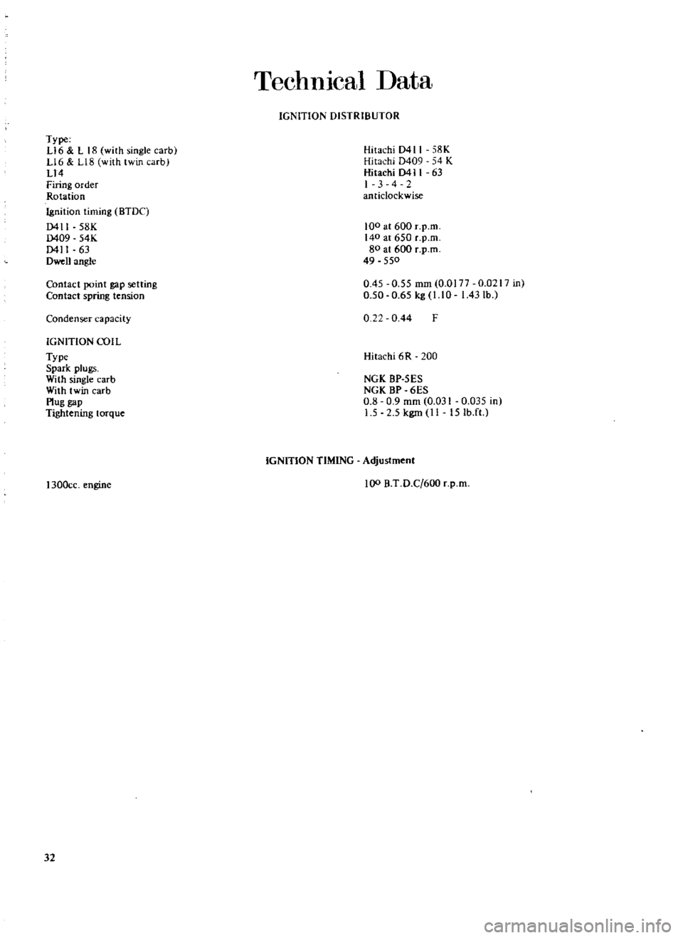
TechnIcal
Data
IGNITION
DISTRIBUTOR
Type
L16
ll8
with
single
carbl
L16
L18
with
twin
arb
L14
Firing
order
Rotation
Ignition
timing
BTDC
0411
58K
0409
54K
0411
63
Dwen
angle
Hitachi
D411
58K
Hitachi
D409
54
K
Hitachi
0411
63
I
3
4
2
anticlockwise
100
at
600
r
p
m
140
at
650
c
p
m
80
at
600
r
p
m
49
550
Contact
point
gap
setting
Contact
spring
tension
0
45
0
55
mm
O
OI77
0
0217
in
0
50
0
65
kg
l
l
0
I
43
lb
Condenser
capacity
0
22
0
44
F
IGNITION
COil
Type
Spark
plugs
With
single
carb
With
twin
carb
Plug
gap
Tightening
torque
Hitachi
6
R
200
NGK
BP
5ES
NGK
BP
6ES
0
8
0
9
mm
0
031
0
035
in
1
5
2
5
kgm
II
15Ib
ft
1300cc
engine
IGNITION
TIMING
Adjustment
100
B
T
D
C
600
r
p
m
32
Page 34 of 171
Fuel
System
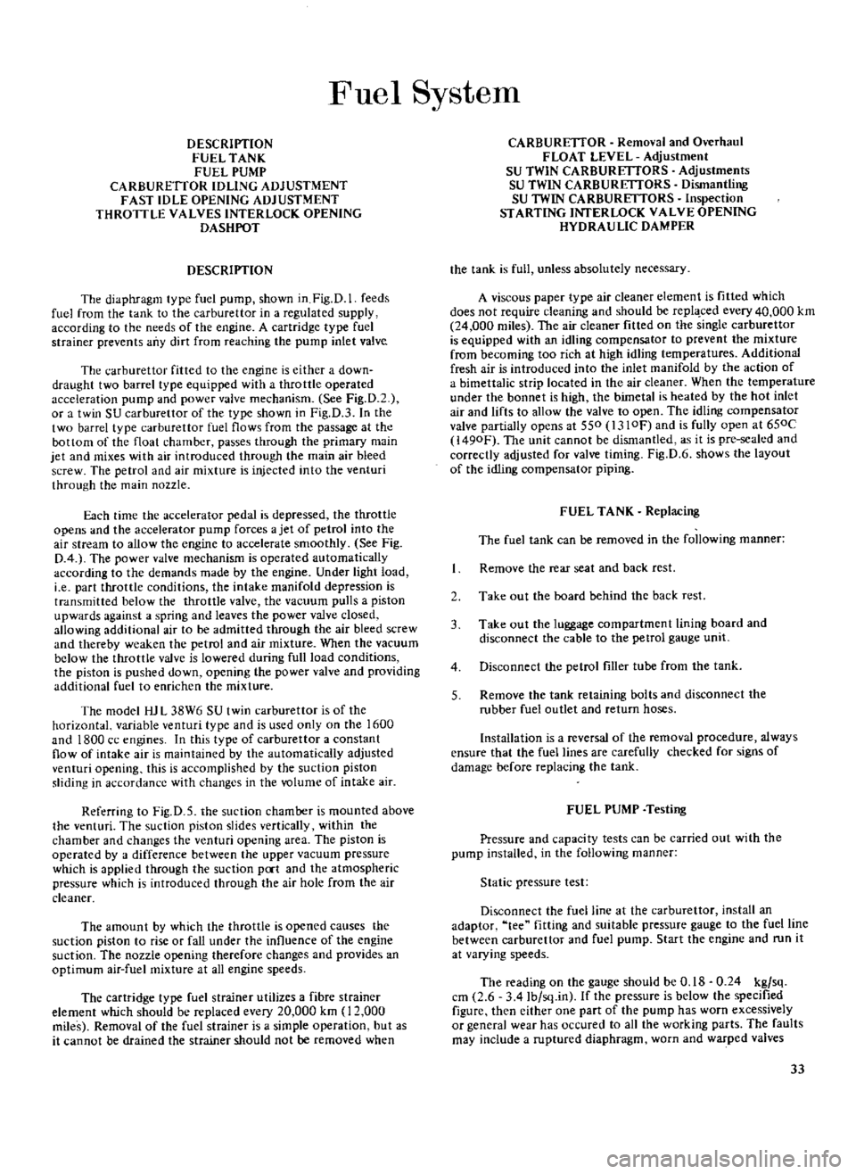
DESCRIPTION
FUEL
TANK
FUEL
PUMP
CARBURETTOR
IDLING
ADJUSTMENT
FAST
IDLE
OPENING
ADJUSTMENT
THROTTLE
VALVES
INTERLOCK
OPENING
DASHPOT
DESCRIPTION
The
diaphragm
type
fuel
pump
shown
in
Fig
D
1
feeds
fuel
from
the
tank
to
the
carburettor
in
a
regulated
supply
according
to
the
needs
of
the
engine
A
cartridge
type
fuel
strainer
prevents
any
dirt
from
reaching
the
pump
inlet
valve
The
carburettor
fitted
to
the
engine
is
either
a
down
draught
two
barrel
type
equipped
with
a
throttle
operated
acceleration
pump
and
power
valve
mechanism
See
Fig
D
2
or
a
twin
SU
carburettor
of
the
type
shown
in
Fig
D
3
In
the
two
barrel
type
carburettor
fuel
flows
from
the
passage
at
the
bottom
of
the
float
chamber
passes
through
the
primary
main
jet
and
mixes
with
air
introduced
through
the
main
air
bleed
screw
The
petrol
and
air
mixture
is
injected
into
the
venturi
through
the
main
nozzle
Each
time
the
accelerator
pedal
is
depressed
the
throttle
opens
and
the
accelerator
pump
forces
a
jet
of
petrol
into
the
air
stream
to
allow
the
engine
to
accelerate
smoothly
See
Fig
0
4
The
power
valve
mechanism
is
operated
automatically
according
to
the
demands
made
by
the
engine
Under
light
load
i
e
part
throttle
conditions
the
intake
manifold
depression
is
transmitted
below
the
throttle
valve
the
vacuum
pulls
a
piston
upwards
against
a
spring
and
leaves
the
power
valve
closed
allowing
additional
air
to
be
admitted
through
the
air
bleed
screw
and
thereby
weaken
the
petrol
and
air
mixture
When
the
vacuum
below
the
throttle
vaJve
is
lowered
during
full
load
conditions
the
piston
is
pushed
down
opening
the
power
valve
and
providing
additional
fuel
to
enrichen
the
mixture
The
model
HJ
L
38W6
SU
twin
carburettor
is
of
the
horizontal
variable
venturi
type
and
is
used
only
on
the
1600
and
1800
cc
engines
In
this
type
of
carburettor
a
constant
flow
of
intake
air
is
maintained
by
the
automatically
adjusted
venturi
opening
this
is
accomplished
by
the
suction
piston
sliding
in
accordance
with
changes
in
the
volume
of
intake
air
Referring
to
Fig
D
5
the
suction
chamber
is
mounted
above
the
venturi
The
suction
piston
slides
vertically
within
the
chamber
and
changes
the
venturi
opening
area
The
piston
is
operated
by
a
difference
between
the
upper
vacuum
pressure
which
is
applied
through
the
suction
poct
and
the
atmospheric
pressure
which
is
introduced
through
the
air
hole
from
the
air
cleaner
The
amount
by
which
the
throttle
is
opened
causes
the
suction
piston
to
rise
or
fall
under
the
intluence
of
the
engine
suction
The
pozzle
opening
therefore
changes
and
provides
an
optimum
air
fuel
mixture
at
all
engine
speeds
The
cartridge
type
fuel
strainer
utilizes
a
fibre
strainer
element
which
should
be
replaced
every
20
000
km
12
000
miles
Removal
of
the
fuel
strainer
is
a
simple
operation
but
as
it
cannot
be
drained
the
strainer
should
not
be
removed
when
CARBURETIOR
Removal
and
Overhaul
FLOAT
LEVEL
Adjustment
SU
TWIN
CARBURmORS
Adjustments
SU
TWIN
CARBURmORS
Dismantling
SU
TWIN
CARBURETTORS
Inspection
STARTING
INTERLOCK
VALVE
OPENING
HYDRAULIC
DAMPER
the
tank
is
full
unless
absolutely
necessary
A
viscous
paper
type
air
cleaner
element
is
fitted
which
does
not
require
cleaning
and
should
be
repl
ced
every
40
000
km
24
000
miles
The
air
cleaner
fitted
on
the
single
carburettor
is
equipped
with
an
idling
compensator
to
prevent
the
mixture
from
becoming
too
rich
at
high
idling
temperatures
Additional
fresh
air
is
introduced
into
the
inlet
manifold
by
the
action
of
a
bimettalic
strip
located
in
the
air
cleaner
When
the
temperature
under
the
bonnet
is
high
the
bimetal
is
heated
by
the
hot
inlet
air
and
lifts
to
allow
the
valve
to
open
The
idling
compensator
valve
partially
opens
at
550
I310F
and
is
fully
open
at
650C
l490F
The
unit
cannot
be
dismantled
as
it
is
pre
sealed
and
correctly
adjusted
for
valve
timing
Fig
D
6
shows
the
layout
of
the
idling
compensator
piping
FUEL
TANK
Replacing
The
fuel
tank
can
be
removed
in
the
following
manner
Remove
the
rear
seat
and
back
rest
2
Take
out
the
board
behind
the
back
rest
3
Take
out
the
luggage
compartment
lining
board
and
disconnect
the
cable
to
the
petrol
gauge
unit
4
Disconnect
the
petrol
filler
tube
from
the
tank
5
Remove
the
tank
retaining
bolts
and
disconnect
the
rubber
fuel
outlet
and
return
hoses
Installation
is
a
reversal
of
the
removal
procedure
always
ensure
that
the
fuel
lines
arc
carefully
checked
for
signs
of
damage
before
replacing
the
tank
FUEL
PUMP
Testing
Pressure
and
capacity
tests
can
be
carried
out
with
the
pump
installed
in
the
following
manner
Static
pressure
test
Disconnect
the
fuel
line
at
the
carburettor
install
an
adaptor
tee
fitting
and
suitable
pressure
gauge
to
the
fuel
line
between
carburettor
and
fuel
pump
Start
the
engine
and
run
it
at
varying
speeds
The
reading
on
the
gauge
should
be
0
18
0
24
kg
sq
cm
2
6
34
Ib
sq
in
If
the
pressure
is
below
the
specified
figure
then
either
one
part
of
the
pump
has
worn
excessively
or
general
wear
has
occured
to
all
the
working
parts
The
faults
may
include
a
ruptured
diaphragm
worn
and
warped
valves
33
Page 38 of 171
Carburettor
type
Throttle
opening
angle
190
200
Dimension
A
213282
341
213282
221
l
3mm
0
051
in
I
4mm
0
056in
If
adjustment
is
required
the
choke
connecting
rod
can
be
carefully
bent
until
the
required
clearance
is
obtained
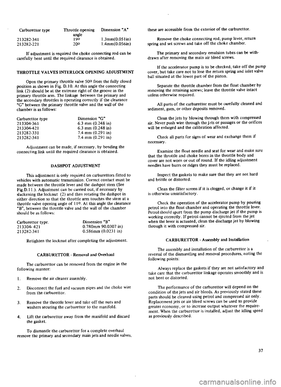
THROTTLE
VALVES
INTERLOCK
OPENING
ADJUSfMENT
Open
the
primary
throttle
valve
500
from
the
fully
closed
position
as
shown
in
Fig
D
I
O
At
this
angle
the
connecting
link
2
should
be
at
the
extreme
right
of
the
groove
in
the
primary
throttle
arm
The
linkage
between
the
primary
and
the
secondary
throttles
is
operating
correctly
if
the
clearance
C
between
the
primary
throttle
valve
and
the
wall
of
the
chamber
is
as
follows
Carburettor
type
213304
361
213304
421
213282
331
213282
341
Dimension
C
6
3
mm
0
248
in
6
3
mm
0
248
in
74
mm
0
291
in
74
mm
0
291
in
Adjustment
can
be
made
if
necessary
by
bending
the
connecting
link
until
the
required
clearance
is
obtained
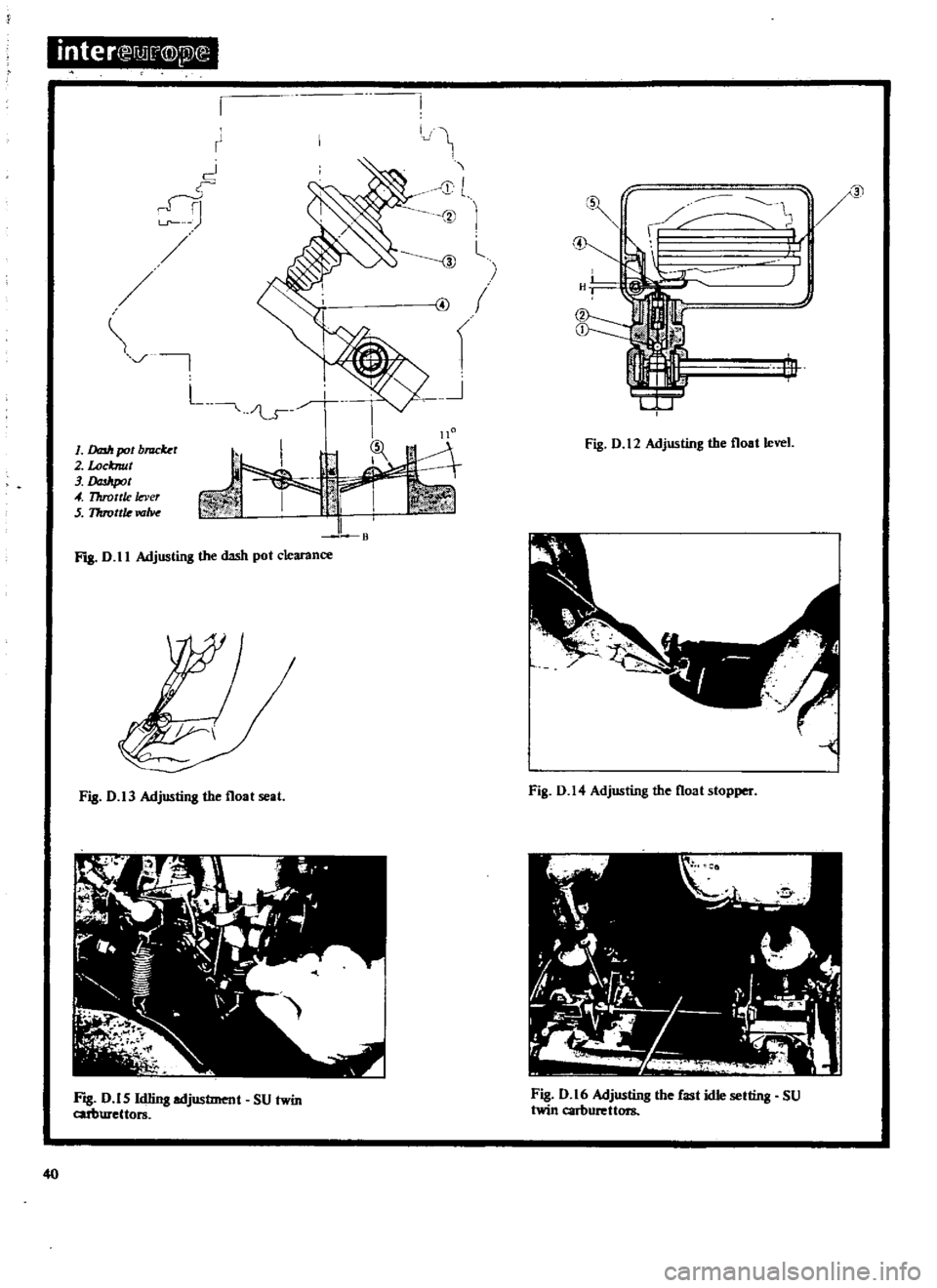
DASHPOT
ADJUSfMENT
This
adjustment
is
only
required
on
carburettors
fitted
to
vehicles
with
automatic
transmission
Correct
contact
must
be
made
between
the
throttle
lever
and
the
dashpot
stem
See
Fig
D
II
Adjustment
can
be
carried
out
if
necessary
by
slackening
the
locknut
2
and
then
rotating
the
dashpot
in
either
direction
so
that
the
throttle
ann
touches
the
stem
at
a
throttle
valve
opening
angle
of
110
At
this
angle
the
clearance
B
between
the
throttle
valve
and
the
wall
of
the
chamber
should
be
as
follows
Carburettor
type
213304
421
213282
341
Dimension
B
0
780mm
90
0307
in
0
586mm
0
0231
in
Retighten
the
locknut
after
completing
the
adjustment
CARBURETTOR
Removal
and
Overhaul
The
carburettor
can
be
removed
from
the
engine
in
the
following
manner
Remove
the
air
cleaner
assembly
2
Disconnect
the
fuel
and
vacuum
pipes
and
the
choke
wire
from
the
carburettor
3
Remove
the
throttle
lever
and
take
off
the
nuts
and
washers
securing
the
carburettor
to
the
manifold
4
Lift
the
carburettor
away
from
the
manifold
and
discard
the
gasket
To
dismantle
the
carburettor
for
a
complete
overhaul
remove
the
primary
and
secondary
main
jets
and
needle
valves
these
are
accessible
from
the
exterior
of
the
carburettor
Remove
the
choke
connecting
rod
pump
lever
return
spring
and
set
screws
and
take
off
the
choke
chamber
The
primary
and
secondary
emulsion
tubes
can
be
with
drawn
after
removing
the
main
air
bleed
screws
If
the
accelerator
pump
is
to
be
checked
take
off
the
pump
cover
but
take
care
not
to
lose
the
return
spring
and
inlet
valve
ball
situated
at
the
lower
part
of
the
piston
Separate
the
throttle
chamber
from
the
float
chamber
by
removing
the
retaining
screws
leave
the
throttle
valve
intact
unless
otherwise
required
All
parts
of
the
carburettor
must
be
ctifefully
cleaned
and
sediment
gum
or
other
deposits
removed
Clean
the
jets
by
blowing
through
them
with
compressed
air
Never
push
wire
through
the
j
ts
or
passages
or
the
orifices
will
be
enlarged
and
the
calibration
affected
Check
all
parts
for
signs
of
wear
and
exchange
them
if
necessary
Examine
the
float
needle
and
seat
for
wear
and
make
sure
that
the
throttle
and
choke
bores
in
the
throttle
body
and
cover
are
not
worn
or
out
of
round
If
the
idling
adjustment
needles
have
burrs
or
ridges
they
must
be
replaced
Inspect
the
gaskets
to
make
sure
that
they
are
not
hard
and
brittle
or
distorted
Oean
the
filter
screen
if
it
is
clogged
or
change
it
if
it
is
otherwist
unsatisfactory
Check
the
operation
of
the
accelerator
pump
by
pouring
petrol
into
the
float
chamber
and
operating
the
throttle
lever
Petrol
should
spurt
from
the
pump
discharge
jet
if
the
pump
is
working
correctly
If
petrol
cannot
be
ejected
from
the
jet
when
the
lever
is
actuated
clean
the
discharge
jet
by
blowing
through
it
with
compressed
air
CARBURETTOR
Assembly
and
Installation
The
assembly
and
installation
of
the
carburettor
is
a
reversal
of
the
dismantling
and
removal
procedures
noting
the
following
points
Always
replace
the
gaskets
if
they
are
not
satisfactory
and
take
care
that
the
carburettor
linkage
operates
smoothly
and
is
not
bent
or
distorted
The
performance
of
the
carburettor
will
depend
on
the
condition
of
the
jets
and
air
bleeds
As
previously
stated
these
pacts
should
be
cleaned
using
petrol
and
compressed
air
only
Replacement
jets
or
air
bleed
screws
can
be
used
to
provide
greater
economy
or
to
increase
output
whatever
the
require
ment
When
the
carburettor
is
installed
adjust
the
idling
speed
as
previously
described
37
Page 39 of 171
inter
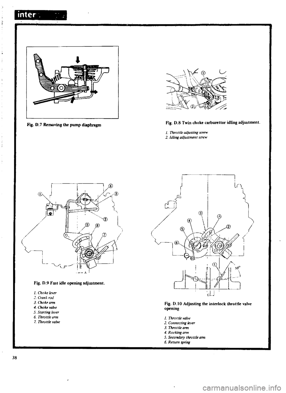
Fig
D
7
Removing
the
pump
diaphragm
Fig
D
S
Twin
choke
carburettor
idling
adjustment
I
TJuottle
odjuJting
Jl
1l
W
2
Idling
adjust
nt
screw
t
c
l
1
cl
rf
C
L
t
0
i
I
SID
jID
L
v
i
s
A
Fig
0
9
Fast
idle
opening
adjustment
I
Choke
lever
Crank
rod
1
a
ok
arm
4
Chob
valve
5
Starring
lever
6
Throttle
ann
7
Throttle
lYl
J1e
Fig
0
10
Adjusting
the
interlock
throttle
valve
opening
J
Throttle
valve
2
Connecling
kv
r
3
Throttle
ann
4
Rocking
ann
5
Secondary
throttle
ann
6
Return
pring
38
Page 41 of 171
inter
nJ
j
Q
i2l
E
I
r
oJ
n
Ln
L
J
fil
B
1
DfD1r
pot
b
r
2
Locknut
3
lJaJItpot
4
Throttle
lever
S
17rrottle
roM
FIB
D
II
Adjusting
the
dash
pot
clearance
Fig
D
13
Adjusting
the
float
seal
Frg
D
15
Id1ing
adjustment
SU
twin
cuburettors
40
i
g
ID
l
i
f
J
Ir
c
11
J
It
Frg
D
12
Adjusting
the
float
level
Fig
D
14
Adjusting
the
float
stopper
Fig
D
16
Adjusting
the
fast
idle
setting
SU
twin
carburettors
Page 42 of 171
1
Oil
cap
nut
2
Suction
chomber
3
Suction
piston
4
Li
tingpin
S
Stop
pin
6
Oil
dDmper
7
Plunger
3
j
I
r
L
2
1
Fig
0
17
Inspecting
the
suction
piston
STlq
O
OO
Fig
D
20
Checking
the
float
level
SU
twin
carburettors
q
J
iT
j
I
@
@
J
1
Conn
ctingrod
2
Wi
guard
3
Choke
lever
4
Connecting
plate
7
S
Thrott
adjusting
SC
Tt
W
6
Fast
id
lever
7
Throttle
adjusting
p1at
8
Throttle
valv
9
Throttlevalv
cletlran
B
Fig
D
22
Adjusting
the
starting
interlock
opening
inteN
lli
i
D
U
I
i
n
1
Jet
n
edle
2
Set
screw
Fig
D
18
Installing
the
jet
needle
1
Nozzle
sleeve
2
Wa
sher
3
Nozz
det
V
d
C1e
W
4
Ad
u
ting
him
5
dlingadjustment
spring
6
Idling
adjustment
nut
Z
Nozz
c
J
Fig
D
l9
Dismantling
the
nozzle
assembly
3
I
Float
lever
2
Bend
here
loadju5t
dimension
H
3
Va
veslem
r
F
Fig
D
21
Adjusting
the
float
level
SU
twin
carburettors
Fig
D
23
Checking
the
damper
oil
41
Page 43 of 171
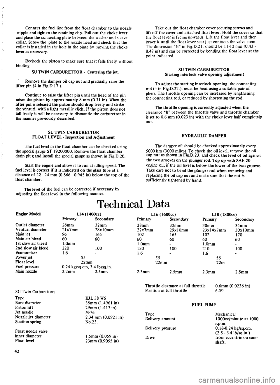
Connect
the
fuel
line
from
the
float
chamber
to
the
nozzle
nipple
and
tighten
the
retaining
clip
Pull
out
the
choke
lever
and
place
the
connecting
plaie
betw
n
the
washer
and
sleeve
collar
Screw
the
plate
to
the
nozzle
head
and
check
that
the
collar
is
installed
in
the
hole
in
the
plate
by
mo
ing
the
choke
lever
as
necessary
Recheck
the
piston
to
make
sure
that
it
falls
freely
without
binding
SU
TWIN
CARBURETTOR
Centering
the
jet
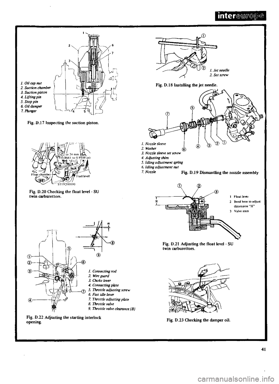
Remove
the
damper
oil
cap
nut
and
gradually
raise
the
lifter
pin
4
in
Fig
D
17
Continue
to
raise
the
lifter
pin
until
the
head
of
the
pin
raises
the
piston
by
approximately
8
mm
0
31
in
When
the
lifter
pin
is
released
the
piston
should
drop
freely
and
strike
the
venturi
with
a
light
metallic
click
If
the
pi
ston
does
not
fall
freely
it
will
be
necessary
to
dismantle
the
carburettor
in
the
manner
previously
described
SU
TWIN
CARBURETTOR
FLOAT
LEVEL
Inspection
and
Adjustment
The
fuel
level
in
the
float
chamber
can
be
checked
using
the
special
gauge
ST
19200000
Remove
the
float
chamber
drain
plug
and
install
the
special
gauge
as
shown
in
Fig
D
20
Start
the
engine
and
allow
it
to
run
at
idling
speed
The
fuel
level
is
conect
if
it
is
indicated
on
the
glass
tu
be
at
a
distance
of
22
24
mm
0
866
0
945
in
below
the
top
of
the
float
chamber
The
level
of
the
fuel
can
be
corrected
if
necessary
by
adjusting
the
float
level
in
the
following
manner
Take
out
the
float
chamber
coveT
securing
screws
and
lift
off
the
cover
and
attached
float
lever
Hold
the
cover
so
that
the
float
lev
r
is
facing
upwards
Lift
the
float
lever
and
then
lower
it
until
the
float
lever
seat
just
contacts
the
valve
stem
The
dimension
uH
in
Fig
D
1
should
be
11
12
mm
0
43
0
47
in
and
can
be
corrected
by
bending
the
float
lever
at
the
point
indicated
SU
TWIN
CARBURETTOR
Starting
interlock
valve
opening
adjustment
To
adjust
the
starting
interlock
opening
the
connecting
rod
4
in
Fig
D
22
1
must
be
bent
using
a
suitable
pair
of
pliers
The
throttle
opening
can
be
increased
by
lengthening
the
connecting
rod
or
reduced
by
shortening
the
rod
The
throttle
opening
is
correctly
adjusted
when
the
clearance
8
between
the
throttle
valve
and
throttle
chamber
is
set
to
0
6
mm
0
023
in
with
the
choke
lever
half
completely
out
HYDRAULIC
DAMPER
The
damper
oil
should
be
checked
approximately
every
5000
km
3000
miles
To
check
the
oil
level
remove
the
oil
cap
nut
as
shown
in
Fig
D
23
and
check
the
level
of
oil
against
the
two
grooves
on
the
plunger
rod
Top
up
with
SAE
20
engine
oil
if
the
oil
level
is
below
the
lower
of
the
two
grooves
Take
care
not
to
bend
the
plunger
rod
when
removing
and
replacing
the
oil
cap
nut
and
make
sure
that
the
nut
is
sufficiently
tightened
by
hand
TechnIcal
Data
Engine
Model
Ll4
I400cc
Primary
Secondary
28mm
32mm
21x7mrn
28xlOmm
96
165
60
60
I
Omm
220
100
1
6
Outlet
diameter
Venturi
diameter
Main
jet
Main
air
bleed
1
st
slow
air
bleed
2nd
slow
air
bleed
Economizer
Power
jet
Float
level
Fuel
pressure
Main
nozzle
55
22mm
0
24
kg
sq
cm
3
41b
sq
in
2
2mm
2
Smm
SU
Twin
Carburettors
Type
Bore
diameter
Piston
lift
Jet
needle
Nozzle
jet
diameter
Suction
spring
IUL
38
W6
38mm
1
4961
in
29mm
1417
in
M
76
2
34
mm
0
0921
in
No
23
Float
needle
valve
inner
diameter
Float
level
1
5mm
0
059
in
23mm
0
9055
in
42
Ll6
1600cc
Primary
Secondary
28mm
32mm
22x7mm
29xlOmm
102
165
60
60
1
0mm
180
100
1
6
Ll8
l80Occ
Primary
Secondary
30mm
34mm
23x14x7mm
30xlOmm
102
170
60
60
I
Omm
210
100
1
6
55
22mm
55
22m
2
3mm
2
5mm
2
3mm
2
8mm
Throttle
clearance
at
full
throttle
Position
at
full
throttle
0
6mm
0
0236
in
6
50
FUEL
PUMP
Type
Delivery
amount
Mechanical
1000cc
minute
at
1000
r
p
m
0
18
0
24
kg
sq
cm
2
5
3
41b
sq
in
from
eccentric
on
cam
shaft
Delivery
pressure
Drive
Page 45 of 171
inter
llD
i
@
p1
11
l
1
14
l
1
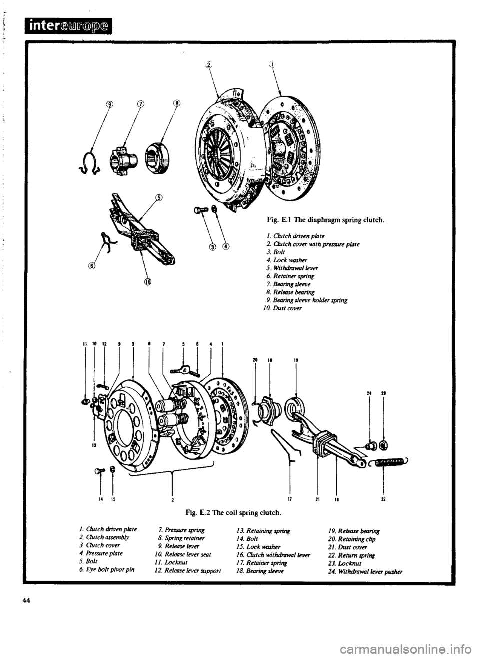
Clutch
driven
pc
e
2
Qutch
assembly
3
Dutch
cover
4
Pressure
plate
5
Bolt
6
Eye
bolt
pivot
pin
81
r
Fig
E
I
The
diaphragm
spring
clutch
1
C7utch
driven
platt
2
Dutch
COl
tT
with
pnsmre
plate
3
8011
4
Lock
washer
5
Withdrawal
lacr
6
Retainer
spring
7
BeaMI
u
ve
8
Relmsf
bearing
9
Beving
s
vc
holder
spring
10
Dust
co
r
11
Fig
E
2
The
coil
spring
clutch
7
Inssure
spring
8
Spring
tainer
9
Release
In
O
10
Retf
t1sc
InleT
seat
11
Locknut
12
Releme
lever
support
19
R
hmr
beDrin8
20
Retaining
clip
21
DllJt
xw0
22
Return
sprint
23
Locknut
24
Wil
u
lnrrJ
raJ
Inn
pusher
44
13
Retaining
SProw
14
8011
15
LockwruheT
16
CTutch
withdrawal
lever
17
Retainer
spring
18
B
ng
sJ
Page 48 of 171
CLUTCH
PEDAL
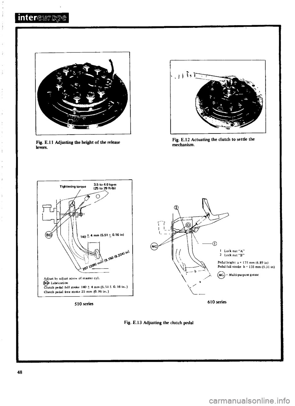
Adjusting
400
and
1600
cc
models
Adjust
the
pedal
height
to
209
mm
8
22
in
with
the
pedal
stop
slackened
off
by
altering
the
length
of
the
master
cylinder
push
rod
See
Fig
E
13
Tighten
the
pedal
stop
and
obtain
a
pedal
height
of
207
ffim
8
15
in
for
Left
Hand
drive
models
or
182
mID
7
I7
in
for
Right
Hand
drive
models
Secure
the
stop
by
tightening
the
locknut
and
make
sure
that
the
points
illustrated
are
correctly
greased
CLlTfCH
PEDAL
Adjusting
1800cc
models
Adjust
the
pedal
height
to
175
mm
6
89
in
by
adjusting
the
pedal
stop
See
Fig
E
13
then
retighten
the
locknut
A
to
a
torque
reading
of
0
79
1
07
kgm
6
8Ib
ft
Turn
the
master
cylinder
push
rod
to
obtain
a
play
between
1
Smm
0
04
0
2
in
at
the
clevis
pin
then
tighten
the
locknut
B
to
a
torque
reading
of
0
79
1
07
kgm
6
8
Ib
ft
Ensure
when
adjusting
the
play
that
the
port
on
the
master
cylinder
is
not
blocked
too
small
a
play
at
the
clevis
pin
may
block
the
port
Bend
the
clevis
pin
over
completely
CLlTfCH
MASTER
CYLINDER
Removal
and
Dismantling
Disconnect
the
push
rod
from
the
clevis
Fig
E
14
Detach
the
fluid
line
from
the
master
cylinder
and
pump
the
fluid
into
a
suitable
container
3
Withdraw
the
retaining
bolts
and
remove
the
master
cylinder
assembly
from
the
vehicle
To
dismantle
the
master
cylinder
remove
the
filler
cap
and
drain
away
the
fluid
Pull
back
the
dust
cover
and
remove
the
snap
ring
the
stopper
push
rod
piston
assembly
and
return
spring
Oean
the
components
in
brake
fluid
and
check
them
for
wear
or
damage
Renew
the
cylinder
and
piston
if
uneven
wear
has
taken
place
the
clearance
between
the
cylinder
and
piston
must
not
exceed
0
13
mm
0
005
in
Renew
the
dust
cover
oil
reservoir
filler
cap
and
fluid
line
if
necessary
Reassembly
of
the
master
cylinder
is
a
reversal
of
the
dismantling
procedure
take
care
to
soak
the
components
in
brake
fluid
and
assemble
them
while
still
wet
When
the
master
cylinder
is
installed
in
the
vehicle
make
sure
that
the
pedal
height
is
adjusted
as
previously
described
and
bleed
the
hydraulic
system
by
following
the
procedures
given
under
the
heading
CLlTfCH
SYSTEM
Bleeding
CLlTfCH
SLAVE
CYLINDER
Removal
and
Dismantling
Remove
the
return
spring
2
Disconnect
the
fluid
line
from
the
slave
cylinder
D
3
Disconnect
the
push
rod
from
the
clutch
withdrawal
lever
4
Take
out
the
mounting
bolts
and
withdraw
the
slave
cylinder
from
the
clutch
housing
To
dismantle
the
slave
cylinder
remove
the
dust
cover
and
snap
ring
and
withdraw
the
remaining
parts
from
the
cylinder
Oean
all
components
carefully
and
check
them
for
signs
of
damage
or
wear
renew
any
part
found
to
be
defective
and
fit
a
new
piston
seal
CLUTCH
SLAVE
CYLINDER
Assembly
and
Installation
Reassembly
is
a
reversal
of
the
dismantling
procedure
Ensure
that
the
parts
are
dipped
in
brake
flu
d
before
assembling
and
that
the
piston
seal
is
correctly
installed
When
the
slave
cylinder
is
installed
in
the
vehicle
bleed
the
hydraulic
system
by
following
the
procedures
given
under
the
heading
CLlTfCH
SYSTEM
Bleeding
The
push
rod
must
be
adjusted
so
that
the
withdrawal
lever
has
an
end
play
of
2
0
2
3
mm
0
078
0
091
in
details
of
this
operation
are
given
below
CLlTfCH
WITHDRAWAL
LEVER
Adjusting
The
correct
adjustment
of
the
clutch
withdrawal
lever
is
most
essential
as
insufficient
clearance
between
the
clutch
release
bearing
and
the
diaphragm
will
cause
the
clutch
to
slip
On
the
other
hand
an
excessive
clearance
will
prevent
the
clutch
from
disengaging
correctly
The
clearance
between
the
release
bearing
and
diaphragm
or
release
levers
can
be
adjusted
in
the
following
manner
Slacken
the
locknut
Fig
E
IS
and
screw
the
push
rod
fully
home
with
the
adjusting
nut
Return
the
adjusting
nut
I
3
4
turns
to
adjust
the
play
at
the
end
of
the
clutch
withdrawal
lever
to
2
0
2
3
mm
0
078
0
091
in
This
will
give
a
clear
ance
of
approximately
1
3
mm
0
051
in
between
the
release
bearing
and
the
diaphragm
spring
or
release
levers
NOTE
When
adjusting
clutch
pedal
free
travel
at
the
withdrawal
lever
it
is
essential
to
check
that
the
clutch
driven
plate
has
not
worn
by
more
than
2mm
0
08
in
otherwise
the
clutch
will
slip
even
if
it
is
correctly
adjusted
See
Technical
Data
for
the
relevant
clutch
driven
plate
thickness
CLUTCH
SYSTEM
Bleeding
The
clutch
system
must
be
bled
after
it
has
been
dismantled
or
if
any
part
of
the
circuit
has
been
opened
This
operation
should
also
be
carried
out
if
the
fluid
level
in
the
reservoir
has
been
allowed
to
fall
and
pennit
air
to
enter
the
system
The
presence
of
air
in
the
system
may
be
noticed
by
incorrect
disengagement
of
the
clutch
but
in
any
case
if
air
is
suspected
the
clutch
must
be
bled
in
the
following
manner
Remove
the
dust
cap
from
the
slave
cylinder
bleed
screw
Connect
a
length
of
tube
to
the
bleed
screw
and
immerse
the
47
Page 49 of 171
inter
1D7
J
3
T
T
aj
W
n
J
I
1
T
f
T
7
e
Fig
E
II
Adjustillll
the
height
of
the
release
levers
Fig
E
12
Actuating
the
clutch
to
settle
the
mechanism
Tightening
torque
3
5
to
4
0
kltm
125
to
29
h
lb
Rs
@
A
l
I
l
1
3
fP
I
01
I
8J
I
Jt
I
Lock
A
2
Lock
ul
Bn
Adjwt
by
adjust
of
master
cyl
@
Lubricatic
l
Clutch
dal
full
trek
140
4
mm
5
51
0
16
Clutch
pedal
free
stroke
25
mm
0
98
Pedal
height
175
mm
6
89
nl
Pc
dalfullstrokc
b
135mm
5
JI
n
@
Multi
purpo
greasc
510
series
610
series
Fig
E
l3
Adjusting
the
clutch
pedal
I
48