engine DATSUN B110 1973 Service Repair Manual
[x] Cancel search | Manufacturer: DATSUN, Model Year: 1973, Model line: B110, Model: DATSUN B110 1973Pages: 513, PDF Size: 28.74 MB
Page 406 of 513
CD
r
Fuel
level
adjustment
@
@
It
I
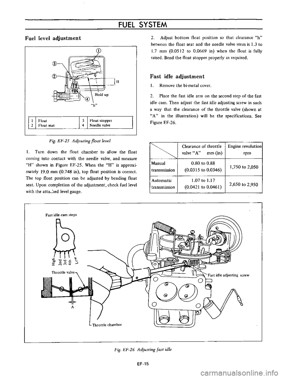
Float
2
Float
seat
FUEL
SYSTEM
2
Adjust
bottom
float
position
so
that
clearance
h
between
the
float
seat
and
the
needle
valve
stem
is
1
3
to
1
7
mm
0
0512
to
0
0669
in
when
the
float
is
fully
raised
Bend
the
float
stopper
properly
as
required
l
lH
H
ld
up
@
h
Fast
idle
adjustment
Remove
the
bi
metal
cover
3
I
Float
stopper
4
Needle
valve
2
Place
the
fast
idle
arm
on
the
second
step
of
the
fast
idle
earn
Then
adjust
the
fast
idle
adjusting
screw
in
such
a
way
that
the
clearance
of
the
throttle
valve
shown
at
A
in
the
illustration
will
be
the
specifications
See
Figure
EF
26
Fig
EF
25
Adjsuting
float
level
Turn
down
the
float
chamber
to
allow
the
float
coming
into
contact
with
the
needle
valve
and
measure
H
shown
in
Figure
EF
25
When
the
H
is
approxi
mately
19
0
mm
0
748
in
top
float
position
is
correct
The
top
float
position
can
be
adjusted
by
bending
float
seat
Upon
completion
of
the
adjustment
check
fuel
level
with
the
atta
led
level
gauge
Clearance
of
throttle
Engine
revolution
valve
A
mm
in
rpm
Manual
0
80
to
0
88
transmission
0
0315
to
0
0346
1
750
to
2
050
Automatic
1
07
to
l
l
7
transmission
0
0421
to
0
0461
2
650
to
2
950
Fast
idle
earn
steps
5
C
0
J
t
E
r
L
E
I
I
Ogc
l
0
0
JO
A
Throttle
chamber
Fig
EF
26
Adjusting
fast
idle
EF
15
Page 407 of 513
ENGINE
Vacuum
break
adjustment
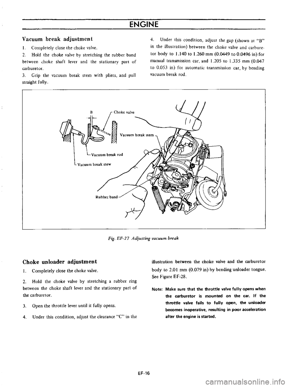
I
Completely
close
the
chuke
valve
2
Hold
the
choke
valve
by
stretching
the
rubber
band
between
hoke
shaft
lever
and
the
sta
tionary
part
of
carburetor
3
Grip
the
vacuum
break
stem
with
pliers
and
pull
straight
fully
Vacuum
break
rod
Vacuum
break
stew
Rubber
band
4
Under
this
condition
adjust
the
gap
shown
at
B
in
the
illustration
between
the
choke
valve
and
carbure
tor
body
to
1
140
to
1
260
mm
0
0449
to
0
0496
in
for
manual
transmission
car
and
1
205
to
1
335
mm
0
047
to
0
053
in
for
automatic
transmission
car
by
bending
vacuum
break
rod
I
Fig
EF
27
Adjusting
vacuum
break
Choke
un
loader
adjustment
I
Completely
close
the
choke
valve
2
Hold
the
choke
valve
by
stretching
a
rubber
ring
between
the
choke
shaft
lever
and
the
stationary
part
of
the
carburetor
3
Open
the
throttle
lever
until
it
fully
opens
4
Under
this
condition
adjust
the
clearance
C
in
the
illustration
between
the
choke
valve
and
the
carburetor
body
to
2
01
mm
0
079
in
by
bending
unloader
tongue
See
Figure
EF
28
Note
Make
sure
that
the
throttle
valve
fully
opens
when
the
carburetor
is
mounted
on
the
car
If
the
throttle
valve
fails
to
fully
open
the
unloader
becomes
inoperative
resulting
in
poor
acceleration
after
the
engine
is
started
EF
16
Page 409 of 513
ENGINE
Adjustment
of
interlock
opening
of
primary
and
secondary
throttle
valves
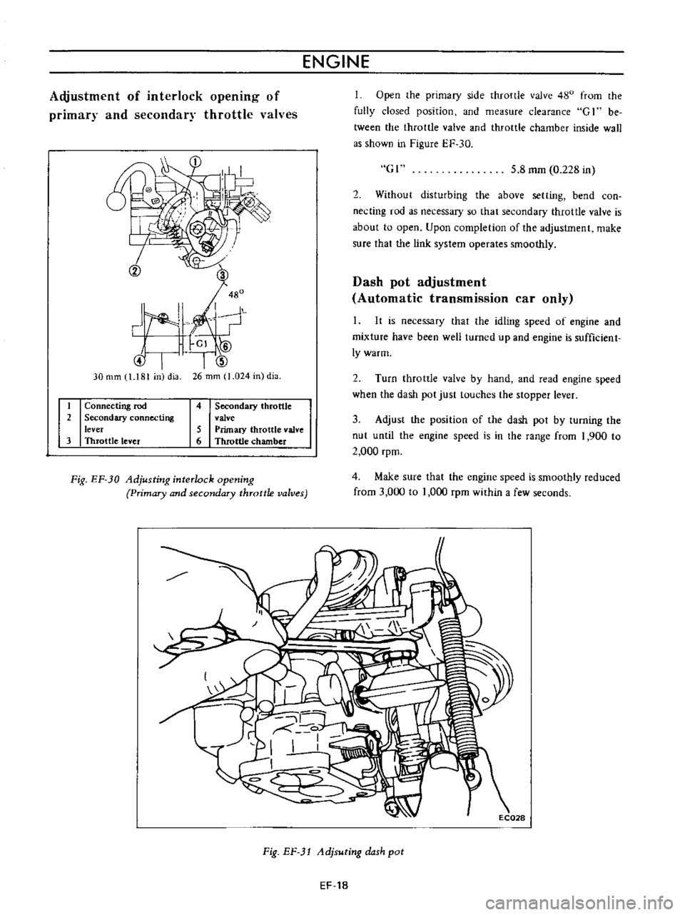
Open
the
primary
side
throttle
valve
480
from
the
fully
closed
position
and
measure
clearance
G
1
be
tween
the
throttle
valve
and
throttle
chamber
inside
wall
as
shown
in
Figure
EF
30
@I
30
rom
1
181
in
dia
Gl
5
8
mm
0
228
in
I
V
2
Without
disturbing
the
above
setting
bend
con
necting
rod
as
necessary
so
that
secondary
throttle
valve
is
about
to
open
Upon
completion
of
the
adjustment
make
sure
that
the
link
system
operates
smoothly
2
Dash
pot
adjustment
Automatic
transmission
car
only
It
is
necessary
that
the
idling
speed
of
engine
and
mixture
have
been
weB
turned
up
and
engine
is
sufficient
Iywarm
2
Turn
throttle
valve
by
hand
and
read
engine
speed
when
the
dash
pot
just
touches
the
stopper
lever
1
Connecting
rod
2
Secondary
connecting
lever
3
Throttle
lever
4
Secondary
throttle
valve
5
Primuy
throttle
valve
6
Throttle
chamber
3
Adjust
the
position
of
the
dash
pot
by
turning
the
nut
until
the
engine
speed
is
in
the
range
from
1
900
to
2
000
rpm
Fig
EF
30
Adjusting
interlock
opening
Primary
and
secondary
throttle
valves
4
Make
sure
that
the
engine
speed
is
smoothly
reduced
from
3
000
to
1
000
rpm
within
a
few
seconds
Fig
EF
1
Adjsuting
dash
pot
EF
18
Page 410 of 513
FUEl
SYSTEM
MA
JOR
SERVICE
OPERATIONS
A
completely
adjusted
and
serviced
carburetor
will
provide
the
engine
with
proper
mixture
at
all
speeds
Periodical
overhauling
which
cleans
all
components
and
passages
will
recover
the
originally
designed
performance
producing
the
engine
with
proper
gasoline
and
air
ratio
at
all
speeds
Passages
and
holes
of
the
carburetor
must
be
cleaned
carefully
Use
only
carburetor
solvent
and
com
pressed
air
to
clean
aU
passages
and
discharge
holes
Never
use
wire
or
other
pointed
tool
otherwise
accurately
calibrated
carburetor
will
be
affected
Removal
Remove
the
air
cleaner
2
Disconnect
the
fuel
line
vacuum
line
automatic
choke
harness
and
anti
dieseling
solenoid
harness
from
carburetor
3
Remove
the
throttle
lever
4
Remove
four
nuts
and
washers
retaining
the
carbuTe
tor
to
the
manifold
if
necessary
5
Lift
the
carburetor
and
remove
from
the
manifold
6
Remove
and
discard
the
gasket
used
between
the
carburetor
and
manifold
Disassembly
The
main
jets
and
needle
valves
on
both
primary
and
secondary
sides
are
accessible
from
outside
of
the
carbure
tor
for
disassembly
2
Remove
throttle
return
spring
3
Remove
pump
lever
shaft
take
out
pump
lever
and
pump
connecting
rod
4
Remove
rubber
pipe
from
choke
piston
5
Loosen
off
bolts
securing
servo
diaphragm
in
posi
tion
take
out
diaphragm
6
Back
off
total
of
five
bolts
which
hold
choke
in
position
and
remove
rods
of
starter
system
take
out
choke
chamber
In
removing
chamber
exercise
care
to
avoid
damaging
float
EF
19
ilia
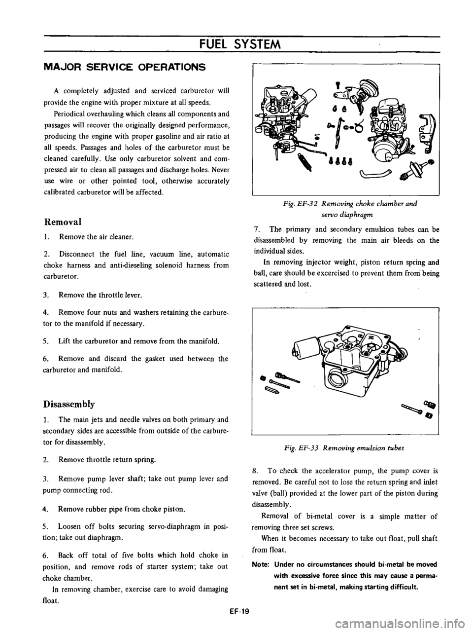
Fig
EF
32
Removing
choke
dwmherand
seroo
diaphragm
7
The
primary
and
secondary
emulsion
tubes
can
be
disassembled
by
removing
the
main
air
bleeds
on
the
individual
sides
In
removing
injector
weight
piston
return
spring
and
ball
care
should
be
excercised
to
prevent
them
from
being
scattered
and
lost
OQ
fI
Fig
EF
33
Removing
emulsion
tubes
8
To
check
the
accelerator
pump
the
pump
cover
is
removed
Be
careful
not
to
lose
the
return
spring
and
inlet
valve
ball
provided
at
the
lower
part
of
the
piston
during
disassemb
ly
Removal
of
bi
metal
cover
is
a
simple
matter
of
removing
three
set
screws
When
it
becomes
necessary
to
take
out
float
pull
shaft
from
float
Note
Under
no
circumstances
should
bi
metal
be
moved
with
excessive
force
since
this
may
cause
a
perma
nent
set
in
bi
metal
making
starting
difficult
Page 411 of 513
ENGINE
Y
Q
0
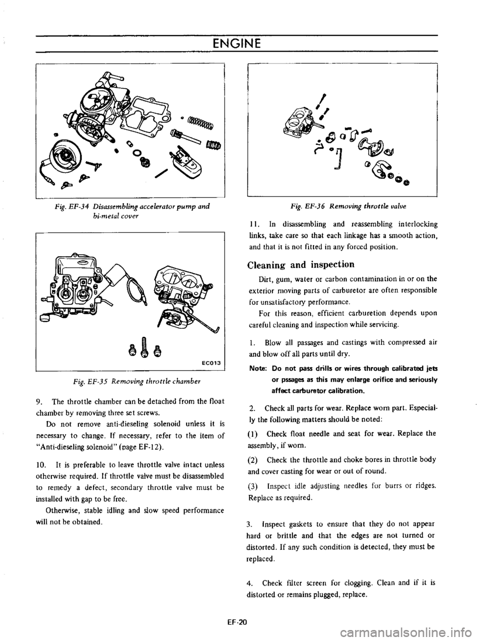
Fig
EF
34
Disassembling
accelerator
pump
and
hi
metal
cover
1
EC013
Fig
EF
35
Removing
throttle
chamber
9
The
throttle
chamber
can
be
detached
from
the
float
chamber
by
removing
three
set
screws
Do
not
remove
anti
dieseling
solenoid
unless
it
is
necessary
to
change
If
necessary
refer
to
the
item
of
Anti
dieseling
solenoid
page
EF
12
10
It
is
preferable
to
leave
throttle
valve
intact
unless
otherwise
required
If
throttle
valve
must
be
disassembled
to
remedy
a
defect
secondary
throttle
valve
must
be
installed
with
gap
to
be
free
Otherwise
stable
idling
and
slow
speed
performance
will
not
be
obtained
I
o
rJ
01
o
o
Fig
EF
36
Removing
throttle
valve
II
In
disassembling
and
reassembling
interlocking
links
take
care
so
that
each
linkage
has
a
smooth
action
and
that
it
is
not
fitted
in
any
forced
position
Cleaning
and
inspection
Dirt
gum
water
or
carbon
contamination
in
or
on
the
exterior
moving
parts
of
carburetor
are
often
responsible
for
unsatisfactory
performance
For
this
reason
efficient
carburetion
depends
upon
careful
cleaning
and
inspection
while
servicing
1
Blow
aU
passages
and
castings
with
compressed
air
and
blow
off
all
parts
until
dry
Note
Do
not
pass
drills
or
wires
through
calibrated
jets
or
pssages
as
this
may
enlarge
orifice
and
seriously
affect
carburetor
calibration
2
Check
all
parts
for
wear
Replace
worn
part
Especial
ly
the
following
matters
should
be
noted
I
Check
float
needle
and
seat
for
wear
Replace
the
assembly
if
worn
2
Check
the
throttle
and
choke
bores
in
throttle
body
and
cover
casting
for
wear
or
out
of
round
3
Inspect
idle
adjusting
needles
fur
burrs
or
ridges
Replace
as
required
3
Inspect
gaskets
to
ensure
that
they
do
not
appear
hard
or
brittle
and
that
the
edges
are
not
turned
or
distorted
If
any
such
condition
is
detected
they
must
be
replaced
4
Check
fIlter
screen
for
clogging
Clean
and
if
it
is
distorted
or
remains
plugged
replace
EF
20
Page 412 of 513
FUEL
SYSTEM
5
Check
venturi
clusters
for
loose
or
worn
parts
If
damage
or
looseness
exists
replace
cluster
assembly
6
Check
the
linkage
for
operating
condition
7
Inspect
the
operation
of
accelerating
pump
Pour
gasoline
into
the
float
chamber
and
operate
the
throttle
lever
Check
condition
of
gasoline
injection
from
the
accelerating
nozzle
Assembly
and
instalIetion
Assemble
and
install
the
carburetor
in
reverse
sequence
of
disassembly
and
removal
Replace
the
gaskets
if
necessary
When
disassembling
and
reassembling
the
interlock
link
and
related
components
be
careful
not
to
bend
or
deform
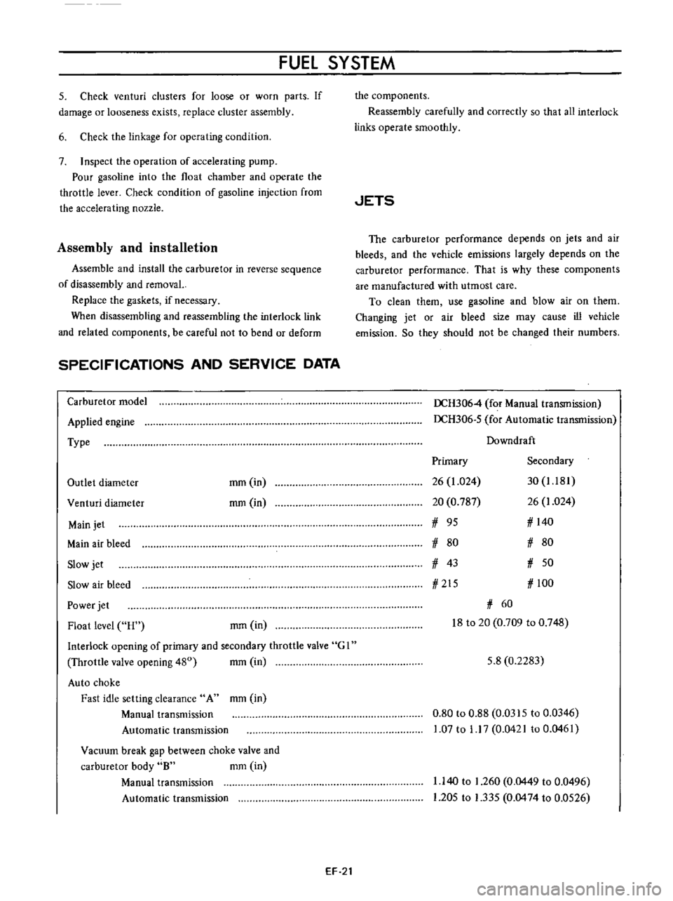
SPECIFICATIONS
AND
SERVICE
DATA
Carburetor
model
Applied
engine
Type
Outlet
diameter
mm
in
rom
in
Venturi
diameter
Main
jet
Main
air
bleed
Slow
jet
Slow
air
bleed
Power
jet
Float
level
H
rom
in
Interlock
opening
of
primary
and
secondary
throttle
valve
G
I
Throttle
valve
opening
480
mm
in
Auto
choke
Fast
idle
setting
clearance
A
mm
in
Manual
transmission
Automatic
transmission
Vacuum
break
gap
between
choke
valve
and
carburetor
body
8
mm
in
Manual
transmission
Automatic
transmission
EF
21
the
components
Reassembly
carefully
and
correctly
so
that
all
interlock
links
operate
smoothly
JETS
The
carburetor
performance
depends
on
jets
and
air
bleeds
and
the
vehicle
emissions
largely
depends
on
the
carburetor
performance
That
is
why
these
components
are
manufactured
with
utmost
care
To
clean
them
use
gasoline
and
blow
air
on
them
Changing
jet
or
air
bleed
size
may
cause
ill
vehicle
emission
So
they
should
not
be
changed
their
numbers
DCH3064
for
Manual
transmission
DCH306
5
for
Automatic
transmission
Downdraft
Primary
Secondary
26
1
024
30
1
181
20
0
787
26
1
024
1
95
1
140
1
80
1
80
1
43
1
50
1
215
1
100
1
60
18
to
20
0
709
to
0
748
5
8
0
2283
0
80
to
0
88
0
0315
to
0
0346
1
07
to
1
17
0
0421
to
0
0461
1
140
to
1
260
0
0449
to
0
0496
1
205
to
1
335
0
0474
to
0
0526
Page 413 of 513
ENGINE
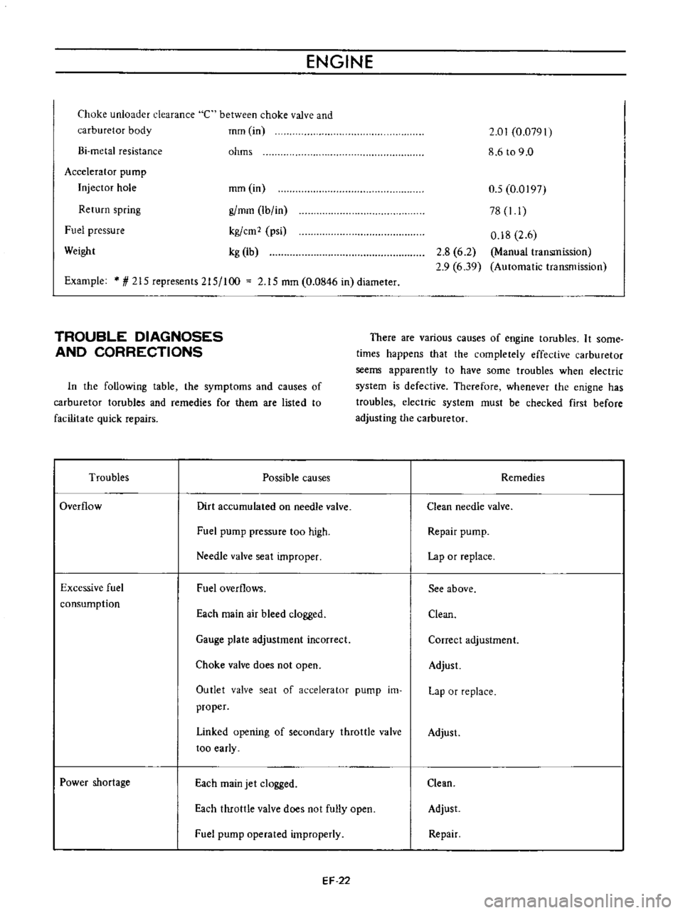
Choke
unloader
clearance
carburetor
body
C
between
choke
valve
and
mm
in
Bi
metal
resistance
ohms
2
01
0
07911
8
6t09
0
Accelerator
pump
Injector
hole
Return
spring
Fuel
pressure
mm
in
g
mm
Ib
in
kg
cm
2
psi
kg
lb
0
5
0
0197
78
I
I
0
18
2
6
Manual
transmission
Automatic
transmission
Weight
2
8
6
2
2
9
6
39
Example
1
215
represents
215
100
2
15
mm
0
0846
in
diameter
TROUBLE
DIAGNOSES
AND
CORRECTIONS
There
are
various
causes
of
engine
tarubles
It
some
times
happens
that
the
completely
effective
carburetor
seems
apparently
to
have
some
troubles
when
electric
system
is
defective
Therefore
whenever
the
enigne
has
troubles
electric
system
must
be
checked
first
before
adjusting
the
carburetor
In
the
following
table
the
symptoms
and
causes
of
carburetor
tarubles
and
remedies
for
them
are
listed
to
facilitate
quick
repairs
Troubles
Possible
causes
Remedies
Overflow
Dirt
accumulated
on
needle
valve
Clean
needle
valve
Fuel
pump
pressure
too
high
Repair
pump
Needle
valve
seat
improper
Lap
or
replace
Excessive
fuel
consumption
Fuel
overflows
See
above
Each
main
air
bleed
clogged
Clean
Gauge
plate
adjustment
incorrect
Correct
adjustment
Choke
valve
does
not
open
Adjust
Outlet
valve
seat
of
accelerator
pump
im
proper
Lap
or
replace
Linked
opening
of
secondary
throttle
valve
too
early
Adjust
Power
shortage
Each
main
jet
clogged
Clean
Each
throttle
valve
does
not
fully
open
Adjust
Fuel
pump
operated
improperly
Repair
EF
22
Page 414 of 513
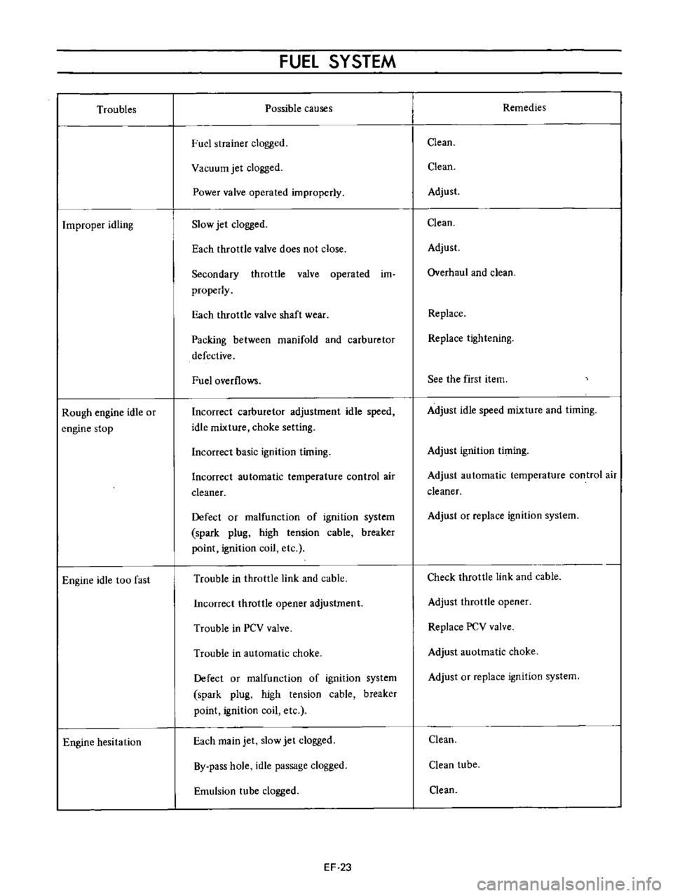
Troubles
Improper
idling
Rough
engine
idle
or
engine
stop
Engine
idle
too
fast
Engine
hesitation
FUEl
SYSTEM
Possible
causes
ruel
strainer
clogged
Vacuum
jet
clogged
Power
valve
operated
improperly
Slow
jet
clogged
Each
throttle
valve
does
not
close
Secondary
throttle
valve
operated
im
properly
Each
throttle
valve
shaft
wear
Packing
between
manifold
and
carburetor
defective
Fuel
overflows
Incorrect
carburetor
adjustment
idle
speed
idle
mixture
choke
setting
Incorrect
basic
ignition
timing
Incorrect
automatic
temperature
control
air
cleaner
Defect
or
malfunction
of
ignition
system
spark
plug
high
tension
cable
breaker
point
ignition
coil
etc
Trouble
in
throttle
link
and
cable
Incorrect
throttle
opener
adjustment
Trouble
in
PCV
valve
Trouble
in
automatic
choke
Defect
or
malfunction
of
ignition
system
spark
plug
high
tension
cable
breaker
point
ignition
coil
etc
Each
main
jet
slow
jet
clogged
By
pass
hole
idle
passage
clogged
Emulsion
tube
clogged
EF
23
Remedies
Clean
Clean
Adjust
Clean
Adjust
Overhaul
and
clean
Replace
Replace
tightening
See
the
first
item
Adjust
idle
speed
mixture
and
timing
Adjust
ignition
timing
Adjust
automatic
temperature
control
air
cleaner
Adjust
or
replace
ignition
system
Check
throttle
link
and
cable
Adjust
throttle
opener
Replace
PCV
valve
Adjust
auotmatic
choke
Adjust
or
replace
ignition
system
Clean
Clean
tube
Clean
Page 415 of 513
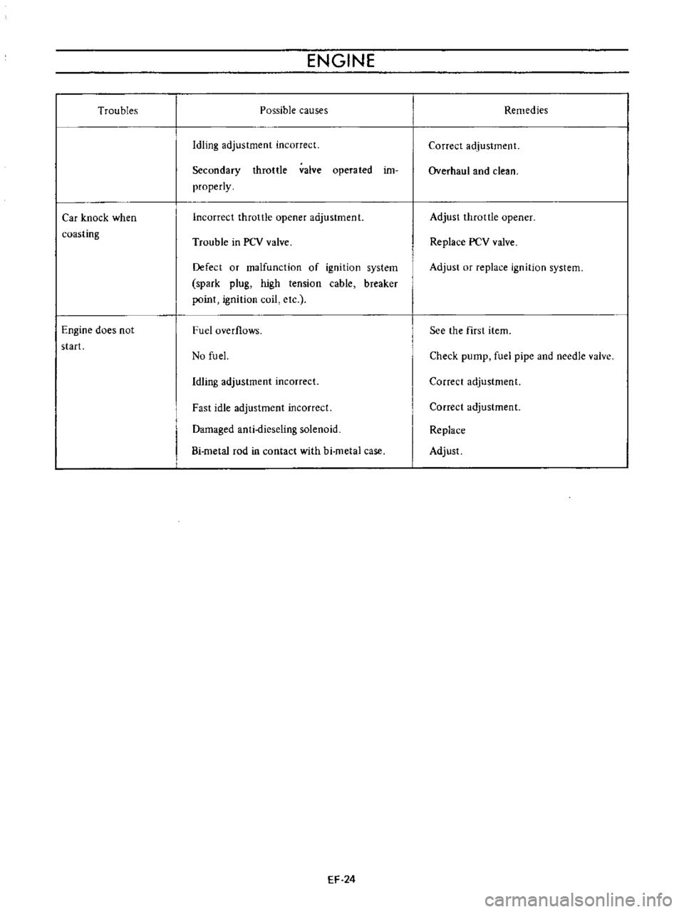
Troubles
Car
knock
when
coasting
Engine
does
not
start
ENGINE
Possible
causes
Idling
adjustment
incorrect
Secondary
throttle
valve
operated
im
properly
Incorrect
throttle
opener
adjustment
Trouble
in
PCV
valve
Defect
or
malfunction
of
ignition
system
spark
plug
high
tension
cable
breaker
point
ignition
coil
etc
Fuel
overflows
No
fu
el
Idling
adjustment
incorrect
Fast
idle
adjustment
incorrect
Damaged
anti
dieseling
solenoid
Bi
metal
rod
in
contact
with
hi
metal
case
EF
24
Remedies
Correct
adjustment
Overhaul
and
clean
Adjust
throttle
opener
Replace
PCV
valve
Adjust
or
replace
ignition
system
See
the
first
item
Check
pump
fuel
pipe
and
needle
valve
Correct
adjustment
Correct
adjustment
Replace
Adjust
Page 416 of 513
FUEl
SYSTEM
EVAPORATIVE
EMISSION
CONTROL
SYSTEM
CONTENTS
OESCRI
PTION
Flow
guide
valve
MAINTENANCE
AND
TESTING
Checking
fuel
tank
vapor
liquid
separator
and
vapor
vent
I
ins
EF
25
EF
26
EF
26
EF
26
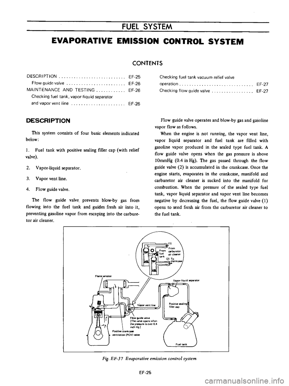
DESCRIPTION
This
system
consists
of
four
basic
elements
indicated
below
I
Fuel
tank
with
positive
sealing
filler
cap
with
relief
valve
2
Vapor
liquid
separator
3
Vapor
vent
line
4
Flow
guide
valve
The
flow
guide
valve
prevents
blow
by
gas
from
flowing
into
the
fuel
tank
and
guides
fresh
air
into
it
preventing
gasoline
vapor
from
escaping
into
the
carbure
tor
air
cleaner
Fl
me
ester
I
f
Flow
Thev
lve
opens
when
thlp
1l
rO
Inch
Hg
O
Positive
unk
venlI1atlon
PCV
hoe
Checking
fuel
tank
vacuum
relief
valve
operation
Checking
flow
guide
valve
EF
27
EF
27
Flow
guide
valve
operates
and
blow
by
gas
and
gasoline
vapor
flow
as
follows
When
the
engine
is
not
running
the
vapor
vent
line
vapor
liquid
separator
and
fuel
tank
are
filled
with
gasoline
vapor
produced
in
the
sealed
type
fuel
tank
A
flow
guide
valve
opens
when
the
gas
pressure
is
above
IOromHg
0
4
in
Hg
The
gas
passed
through
the
flow
guide
valve
2
is
accumulated
in
the
crankcase
Once
the
engine
starts
evaporates
in
the
crankcase
manifold
and
carburetor
air
cleaner
is
sucked
into
the
manifold
for
combustion
When
the
pressure
of
the
sealed
type
fuel
tank
vapor
liquid
separator
and
vapor
vent
line
becomes
negative
by
decreasing
the
fuel
the
flow
guide
valve
I
opens
to
send
fresh
air
from
the
carburetor
air
cleaner
to
the
fuel
tank
lill
K
riquidllepilrflOr
T
VilPOl
vent
line
Positiveteilling
lillercap
Fig
EF
37
Evaporative
emission
control
system
EF
25