engine DATSUN B110 1973 Service Repair Manual
[x] Cancel search | Manufacturer: DATSUN, Model Year: 1973, Model line: B110, Model: DATSUN B110 1973Pages: 513, PDF Size: 28.74 MB
Page 428 of 513
ENGINE
EE022
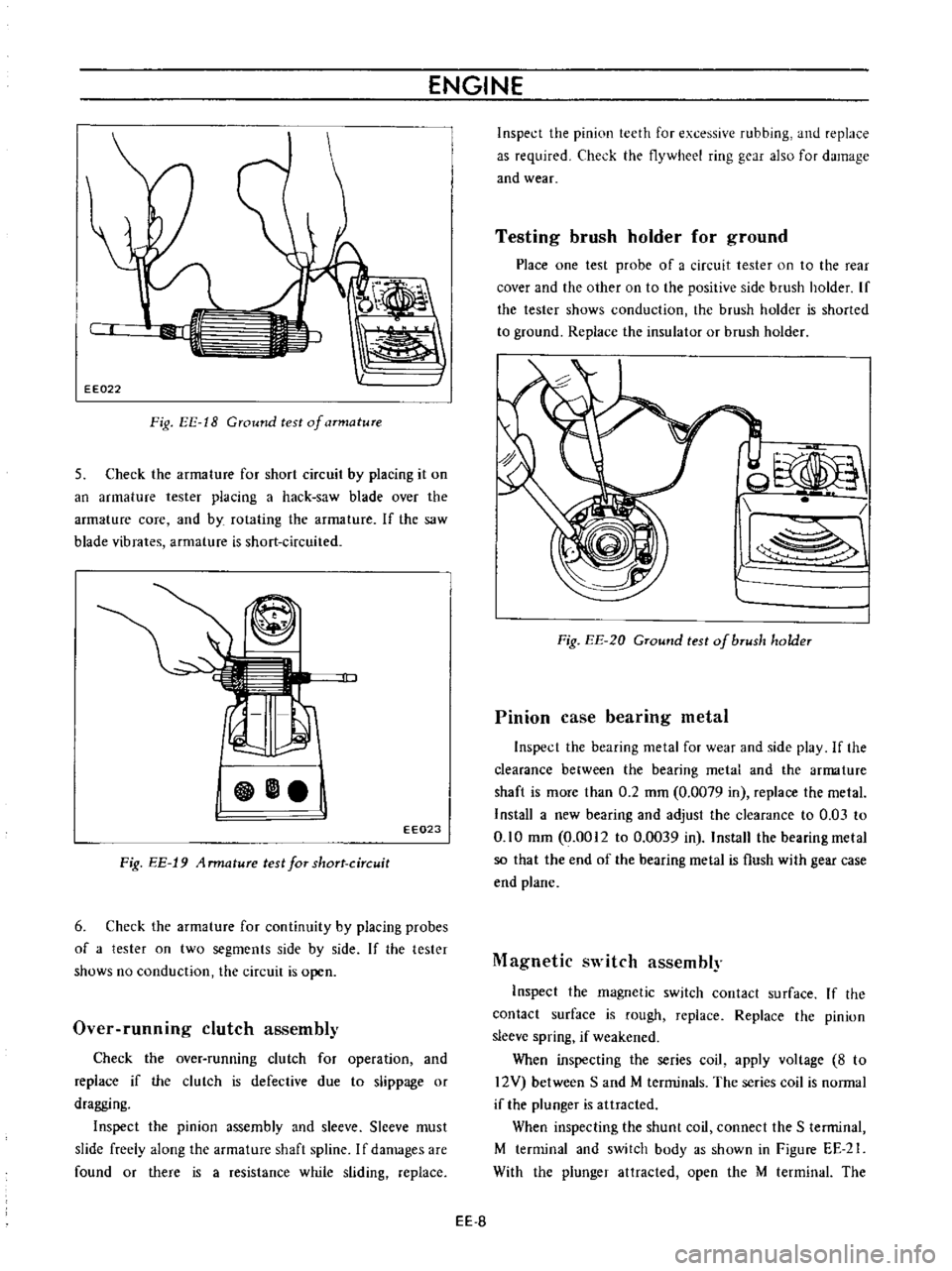
Fig
EE
18
Ground
test
of
armature
5
Check
the
armature
for
short
circuit
by
placing
it
on
an
armature
tester
placing
a
hack
saw
blade
over
the
armature
core
and
by
rotating
the
armature
If
the
saw
blade
vibrates
armature
is
short
circuited
EE023
Fig
EE
19
4
rmature
test
for
short
circuit
6
Check
the
armature
for
continuity
by
placing
probes
of
a
tester
on
two
segments
side
by
side
If
the
tester
shows
no
conduction
the
circuit
is
open
Over
runnmg
clutch
assembly
Check
the
over
running
clutch
for
operation
and
replace
if
the
clutch
is
defective
due
to
slippage
or
dragging
Inspect
the
pinion
assembly
and
sleeve
Slceve
must
slide
freely
along
the
armature
shaft
spline
I
f
damages
are
found
or
there
is
a
resistance
while
sliding
replace
Inspect
the
pinion
teeth
for
excessive
rubbing
and
replace
as
required
Check
the
flywheel
ring
gear
also
for
damage
and
wear
Testing
brush
holder
for
ground
Place
one
test
probe
of
a
circuit
tester
on
to
the
rear
cover
and
the
other
on
to
the
positive
side
brush
holder
If
the
tester
shows
conduction
the
brush
holdcr
is
shorted
to
ground
Replace
the
insulator
or
brush
holder
od
l
Fig
EE
20
GTound
test
of
bTush
holder
Pinion
case
bearing
metal
Inspect
the
bearing
metal
for
wear
and
sidc
play
If
the
clearance
between
the
bearing
metal
and
the
arma
ture
shaft
is
mOTe
than
0
2
mm
0
0079
in
replace
the
metal
Install
a
new
bearing
and
adjust
the
clearance
to
0
03
to
0
10
mm
0
0012
to
0
0039
in
Install
the
bearing
metal
so
that
the
end
of
the
bearing
metal
is
flush
with
gear
case
end
plane
Magnetic
switch
assembly
Inspect
the
magnetic
switch
contact
surface
If
the
contact
surface
is
rough
replace
Replace
the
pinion
sleeve
spring
if
weakened
When
inspecting
the
series
coil
apply
voltagc
8
to
12V
between
Sand
M
terminals
The
series
coil
is
normal
if
the
plunger
is
attracted
When
inspecting
the
shunt
coil
connect
the
S
terminal
M
terminal
and
switch
body
as
shown
in
Figure
EE
21
With
the
plunger
attracted
open
the
M
terminal
The
EE
S
Page 429 of 513
ENGINE
ElECTRICAL
SYSTEM
shunt
coil
is
satisfactory
if
the
plunger
is
attracted
continuously
s
SERIES
COIL
S
SHUNT
COIL
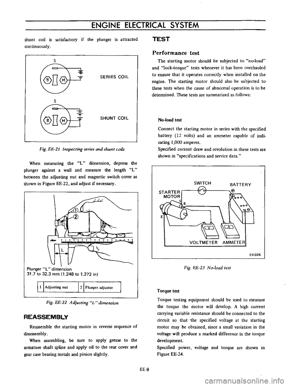
Fig
EE
21
Inspecting
series
and
shunt
coils
When
measuring
the
L
dimension
depress
the
plunger
against
a
wall
and
measure
the
length
L
between
the
adjusting
nut
and
magnetic
switch
cover
as
shown
in
Figure
EE
22
and
adjust
if
necessary
II
L
T
Plunger
L
dimension
31
7
to
32
3
mm
1
248
to
1
272
in
I
11
I
Adjusting
nut
121
Plunger
adjuster
Fig
BE
22
Adjusting
L
dimension
REASSEMBLY
Reassemble
the
starting
motor
in
reverse
sequence
of
disassembly
When
assembling
be
sure
to
apply
grease
to
the
armature
shaft
spline
and
apply
oil
to
the
rear
cover
and
gear
case
bearing
metals
and
pinion
slightly
TEST
Performance
test
The
starting
motor
should
be
subjected
to
no
load
and
lock
torque
tests
whenever
it
has
been
overhauled
to
ensure
that
it
operates
correctly
when
installed
on
the
engine
The
starting
motor
should
also
be
subjected
to
these
tests
when
the
cause
of
abnormal
operation
is
to
be
determined
These
tests
are
summarized
as
follows
No
load
test
Connect
the
starting
motor
in
series
with
the
specified
battery
12
volts
and
an
ammeter
capable
of
indi
cating
1
000
amperes
Specified
current
draw
and
revolution
in
these
tests
are
shown
in
specifications
and
service
data
STARTER
MOTOR
s
SWITCH
o
BATTERY
EtJ
VOLTMETER
AMMETER
EE026
Fig
EE
2J
No
load
test
Torque
test
Torque
testing
equipment
should
be
used
to
measure
the
torque
the
motor
will
develop
A
high
current
carrying
variable
resistance
should
be
connected
to
the
circuit
so
that
the
specified
voltage
at
the
starting
motor
may
be
obtained
since
a
small
variation
in
the
voltage
will
produce
a
marked
difference
in
the
torque
development
Specified
power
voltage
and
torque
are
shown
in
Figure
EE
24
EE
9
Page 430 of 513
ENGINE
Characteristic
curve
i
8
s
l00
0
OJ
m
v
1
2
1
0
tc
0
8
E
u
6
E
o
4
0
2
L
c
0
00
J
300
Current
IAI
Fig
EE
24
Characteristic
curve
of
S
114
B
7M
Diagnoses
of
test
1
Low
speed
with
no
load
and
high
current
draw
may
result
from
following
1
Tight
dirty
or
worn
bearings
2
Bent
armature
shaft
3
Shorted
armature
Check
armature
further
4
Grounded
armature
or
field
Remove
copper
connector
Remove
negative
side
brush
and
insulate
it
from
the
commutator
before
inspection
Using
a
circuit
tester
place
one
probe
on
the
insulated
terminal
and
the
other
on
the
rear
cover
If
the
tester
indicates
conduction
remove
the
other
brush
and
check
field
and
armature
separately
to
determine
whether
the
field
is
grounded
or
armature
is
grounded
2
Failure
to
operate
with
high
current
draw
may
result
from
following
I
Grounded
or
open
field
coil
Inspect
the
connection
and
check
the
circuit
by
the
use
of
a
circuit
tester
2
The
armature
coil
does
not
operate
Inspect
the
commutator
for
excessive
damage
due
to
buring
In
this
case
arc
may
occur
on
defective
commu
tator
during
operating
the
motor
with
no
load
3
Burned
out
commutator
bar
Weak
brush
spring
tension
broken
brush
spring
rubber
brush
thrust
out
of
mica
in
the
commutator
or
a
loose
EE
10
contact
brush
and
commutator
would
cause
burning
of
the
commutator
bar
3
Low
torque
low
current
draw
or
low
no
load
speed
causes
high
internal
resistance
due
to
loose
connections
defective
leads
dirty
commutator
and
causes
listed
on
item
2
3
4
High
no
load
speed
with
low
developed
torque
causes
grounded
field
coil
Replace
the
field
coil
and
check
for
improvement
in
performance
Magnetic
switch
assembly
test
SWITCH
STARTER
MOTOR
61
1u
i
T
0
0118
to
0
0591
n
Fig
EE
25
Circuit
of
magnetic
switch
assembly
test
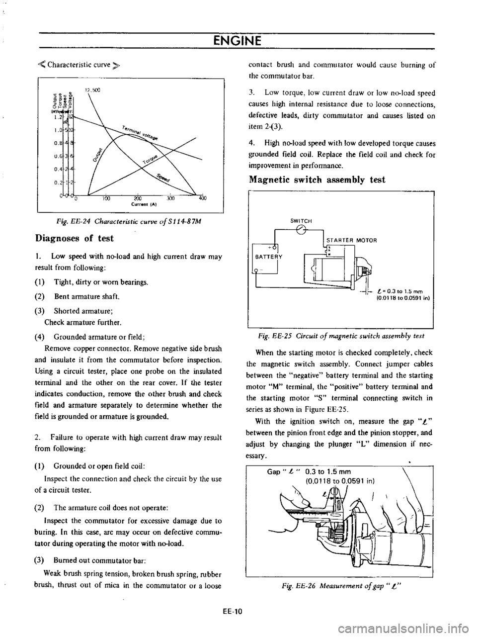
When
the
starting
motor
is
checked
completely
check
the
magnetic
switch
assembly
Connect
jumper
cables
between
the
negative
battery
terminal
and
the
starting
motor
lM
terminal
the
positive
battery
terminal
and
the
starting
motor
S
terminal
connecting
switch
in
series
as
shown
in
Figure
EE
25
With
the
ignition
switch
on
measure
the
gap
I
between
the
pinion
front
edge
and
the
pinion
stopper
and
adjust
by
changing
the
plunger
L
dimension
if
nec
essary
Gap
l
0
3
to
1
5
mm
0
0118
to
0
0591
in
l
Fig
EE
26
Measurement
of
gap
L
Page 431 of 513
ENGINE
ElECTRICAL
SYSTEM
SPECIFICATIONS
AND
SERVICE
DATA
Specifications
Manual
Automatic
Transmission
Transmission
Make
and
type
HITACHI
SI14
87M
HITACHI
S114
156
Nominal
output
KW
1
0
1
0
System
voltage
V
12
12
Weight
kg
Qb
4
6
10
1
54
11
9
No
load
Terminal
voltage
V
12
12
Current
A
less
than
60
less
than
60
Revolution
rpm
more
than
7
000
more
than
6
000
Load
Terminal
voltage
V
6
3
6
3
Current
A
less
than
420
less
than
420
Torque
kg
m
ft
Ib
more
than
0
9
6
5
more
than
1
0
7
2
Shifting
type
of
pinion
gear
Magnetic
shift
Magnetic
shift
Number
of
teeth
on
pinion
gear
9
9
Service
data
S114
87M
S114
156
Brush
length
Standard
height
mm
in
16
0
630
14
0
551
Wear
limit
mm
in
6
5
0
256
4
5
0
177
Brush
spring
tension
Standard
pressure
kg
Qb
1
6
3
5
0
8
1
8
Commutator
Outer
diameter
Standard
OD
mm
in
33
1
299
33
I
299
Wear
limit
mm
in
2
0
079
2
0
079
Difference
between
maximum
and
minimum
diameters
Repair
limit
mm
in
0
4
0
0157
0
4
0
0157
Repair
accuracy
mm
in
0
05
0
0020
0
05
0
0020
Depth
of
mica
Repair
limit
mm
in
0
2
0
0079
0
2
0
0079
Repair
accuracy
mm
in
0
5
to
0
8
0
5
to
0
8
0
0197
to
0
0315
0
0197
to
0
0315
Clearance
between
arma
ture
shaft
and
bushing
mm
in
Repair
limit
0
2
0
0079
0
2
0
0079
Vi
Repair
accuracy
mm
in
0
03
to
0
1
0
03
to
0
1
1
r
0
0012
to
0
0039
0
0012
to
0
003Q
EE
11
Page 432 of 513
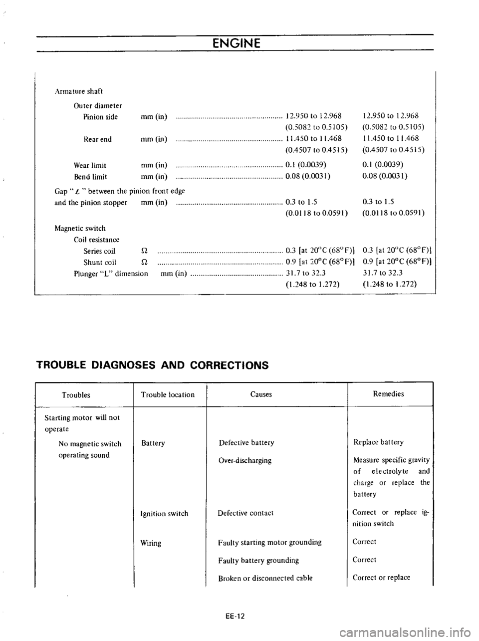
ENGINE
Arma
ture
shaft
Outer
diameter
Pinion
side
mm
in
12
950
to
12
968
0
5082
to
0
5105
11
450
to
II
468
0
4507
to
0
4515
0
1
0
0039
0
08
0
0031
Rear
end
mm
in
Wear
limit
Bend
limit
mm
in
mm
in
Gap
1
between
the
pinion
front
edge
and
the
pinion
stopper
mm
in
0
3
to
1
5
0
0118
to
0
0591
Magnetic
switch
Coil
resistance
Series
cuil
Q
Shunt
coil
n
Plunger
L
dimension
mm
in
0
3
at
20De
68UF
0
9
at
ooe
680F
317t032
3
l
248
to
1
272
TROUBLE
DIAGNOSES
AND
CORRECTIONS
12
950
to
12
968
0
5082
to
0
5105
11
450
to
II
468
0
4507
to
0
4515
l
0
1
0
0039
0
08
0
0031
0
3
to
1
5
0
0118
to
0
0591
0
3
at
20De
680Fl
0
9
at
200e
680F
317
to
32
3
l
248
to
I
272
Troubles
Trouble
location
Causes
Remedies
Starting
motor
will
not
operate
No
magnetic
switch
Battery
Defective
battery
Replace
battery
operating
sound
Over
discharging
Measure
specific
gravity
of
e
Ie
ctrolyte
and
ch
lrge
or
replace
the
battery
Ignition
switch
Defective
contact
Correct
or
replace
ig
nition
switch
Wiring
Faulty
starting
motor
grounding
Correct
Faulty
battery
grounding
Correct
Broken
or
disconnected
cable
Correct
or
replace
EE
12
Page 433 of 513
Magnetic
switch
operating
sound
is
heard
The
starting
motor
rotates
Pinion
gear
does
not
intermesh
with
ring
gear
ENGINE
ELECTRICAL
SYSTEM
Starter
Magnetic
switch
Battery
Wiring
Starting
motor
Magnetic
switch
Ring
gear
Starting
motor
Broken
armature
or
field
coil
cable
Broken
brush
pig
tail
Defective
mica
Broken
or
shorted
series
coil
Faulty
plunger
sliding
Over
discharging
Faulty
terminal
contact
or
loose
connection
Faulty
B
or
M
terminal
connections
Shorted
armature
or
field
coil
Worn
brush
or
improper
spring
pressure
Contaminated
commutator
or
de
fective
mica
Faulty
brush
connection
Seized
metal
Armature
contacted
with
pole
core
Insufficient
plunger
L
dimension
Faulty
contact
Broken
or
shorted
shunt
coil
wire
Worn
teeth
Weakened
pinion
sleeve
spring
Worn
pinion
teeth
EE
13
Replace
Replace
Correct
or
replace
Replace
Repair
or
replace
Measure
specific
gravity
of
electrolyte
arid
charge
if
necessary
Clean
and
retighten
Retighten
Repair
or
replace
Repair
or
replace
Clean
or
repair
Repair
Replace
Repair
or
replace
Adjust
Replace
Replace
Replace
Replace
Replace
Page 434 of 513
Pinion
intermeshes
with
ring
gear
Starting
motor
rotates
and
pinion
intermeshes
with
ring
gear
but
ro
tation
is
too
slow
When
starting
switch
is
set
to
OFF
the
start
ing
motor
does
not
stop
Starting
motor
Battery
Wiring
Ignition
switch
Starting
motor
Ignition
switch
Magnetic
switch
Starting
motor
ENGINE
Faulty
pinion
sliding
Dropped
off
lever
pin
Excessive
plunger
L
dimension
Defective
over
running
clutch
Over
discharging
Improper
or
loose
terminal
contact
Improperly
tightened
connection
Rough
contact
surface
Shorted
armature
coil
or
field
coil
Worn
brush
or
insufficient
spring
pressure
Contaminated
commutator
or
im
proper
brush
contact
Defective
mica
Lack
of
metal
lubrication
Armature
contacted
with
pole
core
Faulty
returning
Seized
contact
Shorted
coil
Faulty
plunger
sliding
Pinion
does
not
disengage
from
the
ring
gear
smoothly
Pinion
spline
does
not
disengage
smoothly
Seized
pinion
metal
EE
14
Repair
Repair
Adjust
Replace
Charge
battery
Repair
and
retighten
Retighten
Repair
or
replace
Repair
or
replace
Repair
or
replace
Repair
Repair
Repair
or
replace
Repair
or
replace
Replace
Replace
Replace
Replace
Repair
or
replace
Repair
or
replace
Replace
Page 435 of 513
ENGINE
ElECTRICAL
SYSTEM
CHARGING
CIRCUIT
IGNITION
1
i
n
ITCH
r
B
i
i
vel
oU
ARMATURE
lip
J
l
t
lJ
FIEL
Df
e
I
I
3
2
I
u
P
5
0
IL
U
p
P
f
H
i
I
I
L
J
L
J
ALTERNATOR
VOL
TAGE
REGULATOR
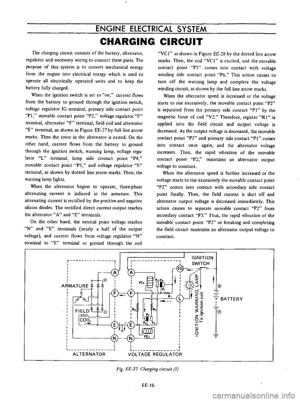
The
charging
circuit
consists
of
the
battery
alternator
regulator
and
necessary
wiring
to
connect
these
parts
The
purpose
of
this
system
is
to
convert
mechanical
energy
from
the
engine
into
electrical
energy
which
is
used
to
operate
all
electrically
operated
units
and
to
keep
the
battery
fully
charged
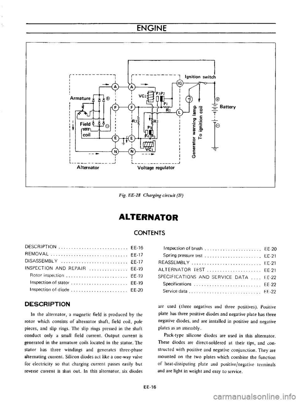
When
the
ignition
switch
is
set
to
on
current
flows
from
the
battery
to
ground
through
the
ignition
switch
voltage
regulator
IG
terminal
primary
side
contact
point
PI
movable
contact
point
P2
voltage
regulator
F
terminal
alternator
F
terminal
field
coil
and
alternator
E
terminal
as
shown
in
Figure
EE
27
by
full
line
arrow
marks
Then
the
rotor
in
the
alternator
is
exited
On
the
other
hand
current
flows
from
the
battery
to
ground
through
the
ignition
switch
warning
lamp
voltage
regu
lator
L
terminal
lamp
side
contact
point
P4
movable
contact
point
PS
and
voltage
regulator
E
terminal
as
shown
by
dotted
line
arrow
marks
Then
the
warning
lamp
ligh
ts
When
the
alternator
begins
to
operate
three
phase
alternating
current
is
induced
in
the
armature
This
alternating
current
is
rectified
by
the
positive
and
negative
silicon
diodes
The
rectified
direct
current
output
reaches
the
alternator
A
and
E
terminals
On
the
other
hand
the
neutral
point
voltage
reaches
N
and
E
terminals
nearly
a
half
of
the
output
voltage
and
current
flows
from
voltage
regulator
N
terminal
to
E
terminal
or
ground
through
the
coil
VCI
as
shown
in
Figure
EE
28
by
the
dolled
line
arrow
marks
Then
the
coil
vc
I
is
excited
and
the
movable
contact
point
P5
comes
into
contact
with
voltage
winding
side
contact
point
P6
This
action
causes
to
turn
off
the
warning
lamp
and
complete
the
voltage
winding
circuit
as
shown
by
the
ullline
arrow
marks
When
the
alternator
speed
is
increased
or
the
voltage
starts
to
rise
excessively
the
movable
contact
point
P2
is
separated
from
the
primary
side
contact
P
1
by
the
magnetic
force
of
coil
V2
Therefore
register
RI
is
applied
into
the
field
circuit
and
output
voltage
is
decreased
As
the
outpu
t
voltage
is
decreased
the
movable
contact
point
P2
and
primary
side
contact
PI
comes
into
contact
once
again
and
the
alternator
voltage
increases
Thus
the
rapid
vibration
of
the
movable
contact
point
P2
maintains
an
alternator
output
voltage
to
constant
When
the
alternator
speed
is
further
increased
or
the
voltage
starts
to
rise
excessively
the
movable
contact
point
P2
comes
into
contact
with
secondary
side
contact
point
finally
Then
the
field
current
is
shut
off
and
alternator
output
voltage
is
decreased
immediately
This
action
causes
to
separate
movable
contact
P2
from
secondary
contact
P3
Thus
the
rapid
vibration
of
the
movable
contact
point
P2
or
breaking
and
completing
the
field
circuit
maintains
an
alternator
output
voltage
to
constant
j
T
SA
TIERY
I
l
e
7
Fig
EE
27
ChaTging
ciTcuit
1
EE
15
Page 436 of 513
ENGINE
r
Ignition
switJ
c
o
iArm
ture
j
i
i
VC2
P
tP2
d
I
I
I
PI
I
ll
Rl
L
I
I
lRJ
t
R
I
Field
e
I
I
I
I
Ps
I
1
I
I
n
I
coil
M
4
i
f
I
L
1
J
Alternator
Voltage
regulator
Fig
EE
2B
ChaTging
ciTcuit
II
ALTERNATOR
CONTENTS
DESCRIPTION
REMOVAL
DISASSEMBL
Y
INSPECTION
AND
REPAIR
Rotor
inspection
Inspection
of
stator
I
nspection
of
diode
EE
16
EE
17
EE
17
EE
19
EE
19
EE
19
EE
20
DESCRIPTION
In
the
alternator
a
magnetic
field
is
produced
by
the
rotor
which
consists
of
alternator
shaft
field
coil
pole
pieces
and
slip
rings
The
slip
rings
pressed
in
the
shaft
conduct
only
a
small
field
current
Output
current
is
generated
in
the
armature
coils
located
in
the
stator
The
stator
has
three
windings
and
generates
three
phase
alternating
currenl
Silicon
diudes
act
like
a
one
way
valve
for
electricity
so
that
charging
currcnt
passes
easily
but
reverse
current
is
shut
out
In
this
alternator
six
diodes
0
E
0
c
co
0
E
c
o
0
c
Cl
Battery
T
e
I
nspection
of
brush
Spring
pressure
test
REASSEMBL
Y
ALTERNATOR
TEST
SPECIFICATIONS
AND
SERVICE
DATA
Specifications
Service
data
EE
20
EE
21
EE
21
EE
21
EE
22
EE
22
EE
22
are
used
three
negatives
and
three
positives
Positive
plate
has
three
positive
diodes
and
negative
plate
has
three
negative
diodes
and
are
installed
in
positive
and
negative
plates
as
an
assembly
Pack
type
silicone
diodes
are
used
in
this
alternator
These
diodes
are
direct
soldered
at
their
tips
and
con
structed
with
positive
and
negative
conjunction
They
are
mounted
on
the
two
plates
which
combine
the
function
of
heat
dissipating
plate
and
positive
negative
terminals
and
are
light
in
weight
and
easy
to
service
EE
16
Page 437 of 513
ENGINE
ElECTRICAL
SYSTEM
CD
@
@
@
y
@
1
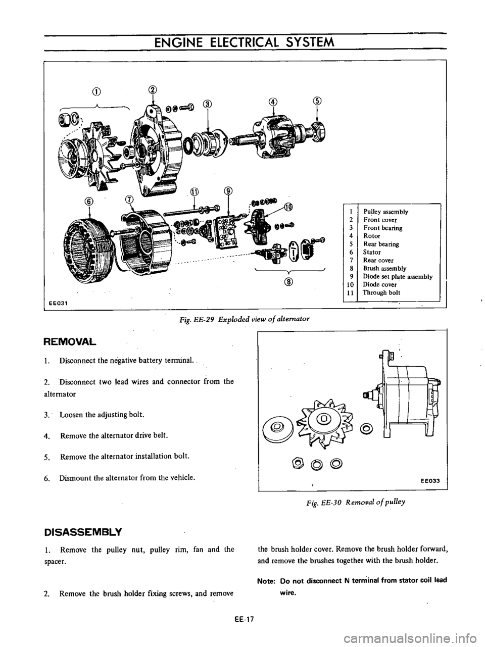
Pulley
assembly
2
Front
cover
3
Front
bearing
4
Rotor
5
Rear
bearing
6
Stator
7
Rear
cover
8
Brush
assembly
9
Diode
set
pl
te
assembly
10
Diode
cover
Jl
Through
bolt
EE031
Fig
EE
29
Exploded
view
of
altematoT
REMOVAL
3
Loosen
the
adjusting
bolt
@
o
lL
1
Disconnect
the
negative
battery
terminal
2
Disconnect
two
lead
wires
and
connector
from
the
alternator
4
Remove
the
alternator
drive
belt
@
J
5
Remove
the
alternator
installation
bolt
@@@
6
Dismount
the
alternator
from
the
vehicle
EE033
Fig
EE
JO
Removal
of
pulley
DISASSEMBLY
l
Remove
the
pulley
nut
pulley
rim
fan
and
the
spacer
the
brush
holder
cover
Remove
the
brush
holder
forward
and
remove
the
brushes
together
with
the
brush
holder
2
Remove
the
brush
holder
fixing
screws
and
remove
Note
Do
not
disconnect
N
term
inal
from
stator
coil
lead
wire
EE
17