light DATSUN B110 1973 Service Owner's Manual
[x] Cancel search | Manufacturer: DATSUN, Model Year: 1973, Model line: B110, Model: DATSUN B110 1973Pages: 513, PDF Size: 28.74 MB
Page 133 of 513
7
Remove
the
brake
disc
installation
bolt
and
remove
the
brake
disc
from
the
spindle
8
Disassemble
the
wheel
cylinders
Inspection
l
Drums
If
they
show
score
excessive
out
of
round
and
so
forth
reconditioning
by
machining
is
required
Brake
drum
inner
diameter
203
2
mm
8
00
in
Drum
inside
out
of
roundness
Below
0
02
mm
0
0008
in
Max
allowable
drum
inner
diameter
204
5
mm
8
051
in
2
Linings
If
brake
shoe
linings
are
incomp1etedly
seated
soiled
or
greasy
or
deteriorated
due
to
excessive
heating
repair
or
replace
them
If
the
thickness
of
the
lining
is
less
than
1
5
mm
0
0591
in
replace
it
Note
a
If
oil
or
grease
is
found
on
linings
clean
thoroughly
with
carbon
tetrachloride
or
gasoline
b
After
installing
and
bonding
lining
grind
the
lining
face
to
a
diameter
equal
to
the
brake
drum
3
Check
the
adjusting
cams
for
their
smooth
operation
4
Return
springs
If
they
are
considerably
weak
replace
them
Return
spring
dimension
Wire
diameter
x
free
length
turns
3
2
x
118
mm
20
5
0
1260
x
4
65
in
20
5
Load
x
length
55
kg
I21
lb
x
127
1
mm
5
00
in
13
4
0
528
ilL
rnv
0
t
6
hl
03
118
4
65
FREE
LENGTH
UNIT
mm
in
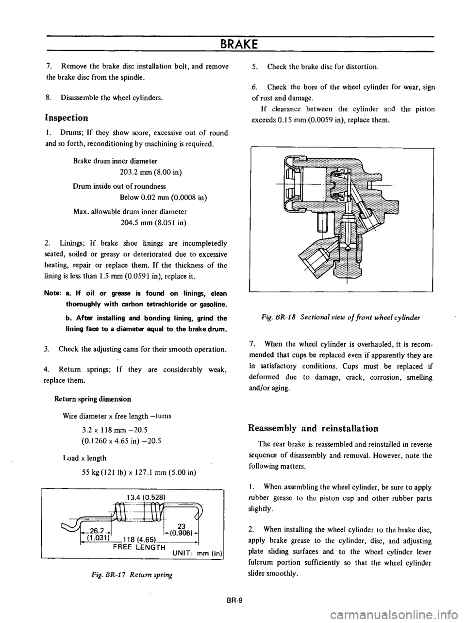
Fig
BR
J
7
Return
spring
BRAKE
5
Check
the
brake
disc
for
distortion
6
Check
the
bore
of
the
wheel
cylinder
for
wear
sign
of
rust
and
damage
If
clearance
between
the
cylinder
and
the
piston
exceeds
0
15
mm
0
0059
in
replace
them
Fig
BR
J
8
Sectional
view
of
front
wheel
cylinder
7
When
the
wheel
cylinder
is
overhauled
it
is
recom
mended
that
cups
be
replaced
even
if
apparently
they
are
in
satisfactory
conditions
Cups
must
be
replaced
if
deformed
due
to
damage
crack
corrosion
smelling
andf
or
aging
Reassembly
and
reinstallation
The
rear
brake
is
reassembled
and
reinstalled
in
reverse
sequence
of
disassembly
and
removal
However
note
the
following
matters
When
assembling
the
wheel
cylinder
be
sure
to
apply
rubber
grease
to
the
piston
cup
and
other
rubber
parts
slightly
2
When
installing
the
wheel
cylinder
to
the
brake
disc
apply
brake
grease
to
the
cylinder
disc
and
adjusting
plate
sliding
surfaces
and
to
the
wheel
cylinder
lever
fulcrum
portion
sufficiently
so
that
the
wheel
cylinder
slides
smoothly
BR
9
Page 139 of 513
BRAKE
i
f
F
PISTON
A
PISTON
S
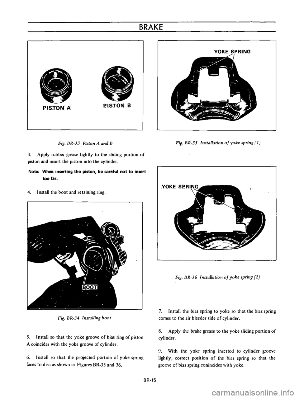
Fig
BR
33
Piston
A
and
B
3
Apply
rubber
grease
lightly
to
the
sliding
portion
of
piston
and
insert
the
piston
into
the
cylinder
Note
When
inserting
the
piston
be
careful
not
to
insert
too
far
4
1
nstaU
the
boot
and
retaining
ring
Fig
BR
34
Installing
boot
5
Install
so
that
the
yoke
groove
of
bias
ring
of
piston
A
coincides
with
the
yoke
groove
of
cylinder
6
Install
so
that
the
projected
portion
of
yoke
spring
faces
to
disc
as
shown
in
Figures
BR
35
and
36
BR
15
YOKE
SPRING
Fig
BR
35
Installation
of
yoke
spring
1
Fig
BR
36
Installation
of
yoke
spring
2
7
Install
the
bias
spring
to
yoke
so
that
the
bias
spring
comes
to
the
air
bleeder
side
of
cylinder
8
Apply
the
brake
grease
to
the
yoke
sliding
portion
of
cylinder
9
With
the
yoke
spring
inserted
to
cylinder
groove
lightly
correct
position
of
the
bias
spring
so
that
the
groove
of
bias
spring
conincides
with
yoke
Page 140 of 513
CHASSIS
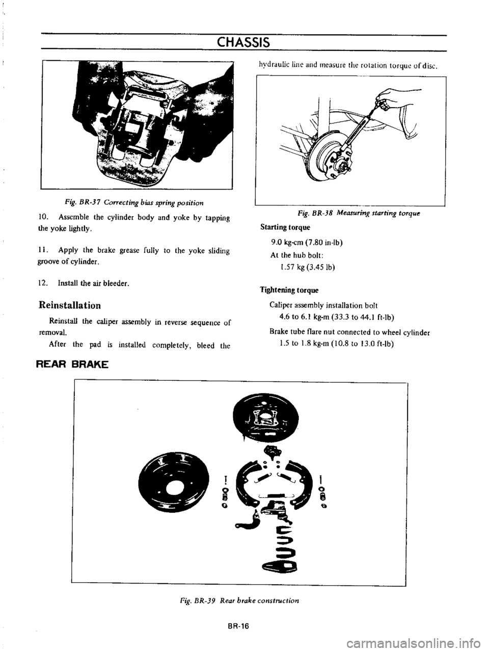
Fig
BR
37
Correcting
bias
spring
position
10
Assemble
the
cylinder
body
and
yoke
by
tapping
the
yoke
lightly
11
Apply
the
brake
grease
fully
to
the
yoke
sliding
groove
of
cylinder
12
Install
the
air
bleeder
Reinstallation
Reinstall
the
caliper
assembly
in
reverse
sequence
of
removal
After
the
pad
is
installed
completely
bleed
the
REAR
BRAKE
r
e
hydraulic
line
and
measure
the
rotation
torque
of
disc
Fig
BR
38
Measuring
starting
torque
Starting
torque
9
0
kg
cm
7
80
in
lb
At
the
hub
bolt
1
57
kg
3
45
lb
Tightening
torque
Caliper
assembly
installation
bolt
4
6
to
6
kg
m
33
3
to
44
1
ft
lb
Brake
tube
flare
nut
connected
to
wheel
cylinder
1
5
to
1
8
kg
m
10
8
to
3
0
ft
lb
JJ
i
o
C
EID
I
o
fj
t
Fig
BR
39
Rear
brake
construction
BR
16
Page 144 of 513
CHASSIS
4
With
the
hand
brake
lever
pulled
depress
the
push
button
and
make
sure
that
the
pawl
disengages
the
teeth
when
the
push
button
is
depressed
5
to
6
mm
0
1969
to
0
2362
in
completely
5
Make
sure
that
the
cable
dust
cover
is
not
damaged
or
warped
Reinstallation
Reinstall
the
hand
brake
in
reverse
sequence
of
removal
noting
the
following
matters
Be
careful
not
to
damage
or
twist
the
dust
cover
2
Tighten
the
hanger
strap
and
the
cable
connecting
nut
to
0
8
to
1
0
kg
m
5
8
to
7
2
ft
1b
3
When
adjusting
rear
brake
shoe
clearance
be
sure
to
loosen
the
inner
cable
sufficiently
4
Grease
the
sliding
parts
with
multi
purpose
grease
MIL
G
2108
or
G
10924
AD
JUSTMENT
Brake
shoe
clearance
Front
drum
brake
Jack
up
the
vehicle
and
remove
the
wheeL
2
With
the
brake
drum
installed
tighten
the
cam
adjusting
stud
clockwise
up
to
such
an
extent
that
the
brake
shoe
comes
into
contact
with
the
brake
drum
by
applying
your
hand
and
tool
from
reverse
side
of
the
brake
disc
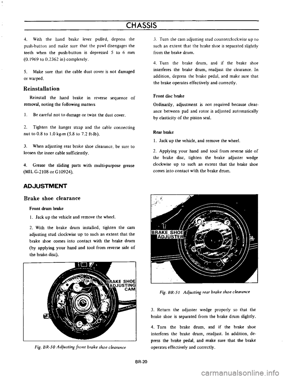
Fig
BR
50
Adjusting
front
brake
shoe
clearance
Turn
the
cam
adjusting
5
ud
counterclockwise
up
to
such
an
extent
that
the
brake
shoe
is
separated
slightly
from
the
brake
drum
4
Turn
the
brake
drum
and
if
the
brake
shoe
interferes
the
brake
drum
readjust
the
clearance
In
addition
depress
the
brake
pedal
and
make
sure
that
the
brake
operates
effectively
and
correctly
Front
disc
brake
Ordinarily
adjustment
is
not
required
because
clear
ance
between
pad
and
rotor
is
adjusted
automatically
by
elasticity
of
the
piston
seal
Rear
brake
Jack
up
the
vehicle
and
remove
the
wheeL
2
Appiying
your
hand
and
tool
from
reverse
side
of
the
brake
disc
tighten
the
brake
adjuster
wedge
clockwise
up
to
such
an
extent
that
the
brake
shoe
comes
into
contact
with
the
brake
drum
Fig
BR
51
Adjusting
rear
brake
shoe
clearance
3
Return
the
adjuster
wedge
properly
so
that
the
brake
shoe
is
separated
from
the
brake
drum
slightly
4
Turn
the
brake
drum
and
if
the
brake
shoe
interferes
the
brake
drum
readjust
In
addition
de
press
the
brake
pedal
and
make
sure
that
the
brake
operates
effectively
and
correctly
BR
20
Page 149 of 513
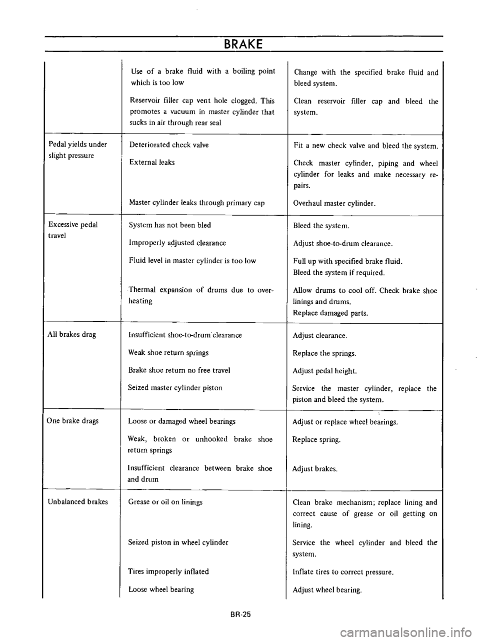
Pedal
yields
under
slight
pressure
Excessive
pedal
travel
All
brakes
drag
One
brake
drags
Unbalanced
brakes
BRAKE
Use
of
a
brake
fluid
with
a
boiling
point
which
is
too
low
Reservoir
filler
cap
ven
t
hole
clogged
This
promotes
a
vacuum
in
master
cylinder
that
sucks
in
air
through
rear
seal
Deteriorated
check
valve
External
leaks
Master
cylinder
leaks
through
primary
cap
System
has
not
been
bled
Improperly
adjusted
clearance
Fluid
level
in
master
cylinder
is
too
low
Thermal
expansion
of
drums
due
to
over
heating
Insufficient
shoe
tlrdrum
clearance
Weak
shoe
return
springs
Brake
shoe
return
no
free
travel
Seized
master
cylinder
piston
Loose
or
damaged
wheel
bearings
Weak
broken
or
unhooked
brake
shoe
return
springs
Insufficient
clearance
between
brake
shoe
and
drum
Grease
or
oil
on
linings
Seized
piston
in
wheel
cylinder
Tires
improperly
inflated
Loose
wheel
bearing
BR
25
Change
with
the
specified
brake
fluid
and
bleed
system
Clean
reservoir
filler
cap
and
bleed
the
system
Fit
a
new
check
valve
and
bleed
the
system
Check
master
cylinder
piping
and
wheel
cylinder
for
leaks
and
make
necessary
re
pairs
Overhaul
master
cylinder
Bleed
the
system
Adjust
shoe
to
drum
clearance
Full
up
with
specified
brake
fluid
Bleed
the
system
if
required
Allow
drums
to
cool
off
Check
brake
shoe
linings
and
drums
Replace
damaged
parts
Adjust
clearance
Replace
the
springs
Adjust
pedal
height
Service
the
master
cylinder
replace
the
piston
and
bleed
the
system
Adjust
or
replace
wheel
bearings
Replace
spring
Adjust
brakes
Clean
brake
mechanism
replace
lining
and
correct
cause
of
grease
or
oil
getting
on
lining
Service
the
wheel
cylinder
and
bleed
the
system
Inflate
tires
to
correct
pressure
Adjust
wheel
bearing
Page 158 of 513
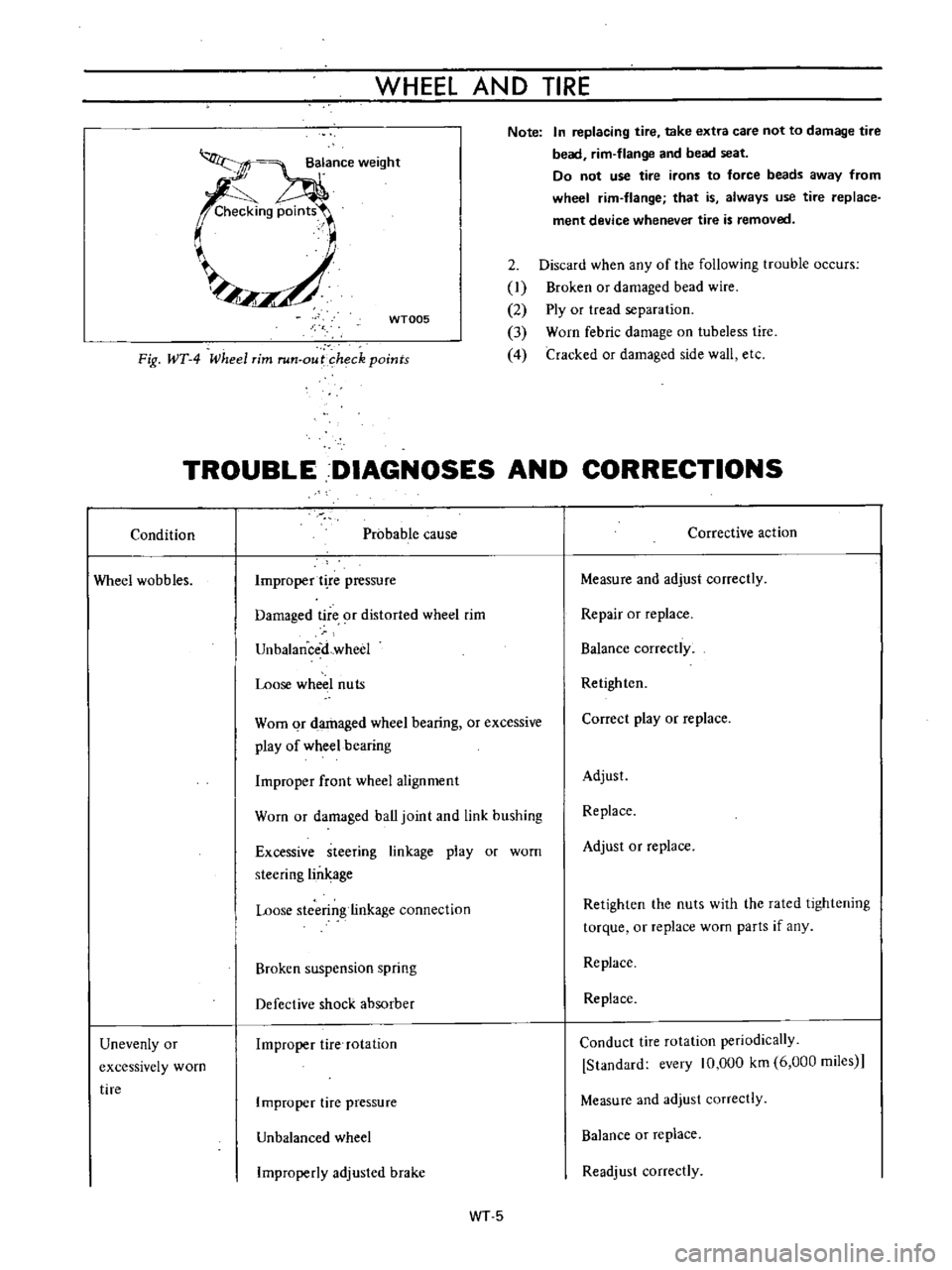
WHEEL
AND
TIRE
Note
In
replacing
tire
take
extra
care
not
to
damage
tire
bead
rim
flange
and
bead
seat
Do
not
use
tire
irons
to
force
beads
away
from
wheel
rim
flange
that
is
always
use
tire
replace
ment
device
whenever
tire
is
removed
WT005
2
Discard
when
any
of
the
following
trouble
occurs
I
Broken
or
damaged
bead
wire
2
Ply
or
tread
separation
3
Worn
febric
damage
on
tubeless
tire
4
Cracked
or
damaged
side
wall
etc
Fig
WT
4
Wheel
rim
run
out
heck
points
TROUBLE
DIAGNOSES
AND
CORRECTIONS
Condition
Probable
cause
Corrective
action
Wheel
wobbles
Improper
t
re
pressure
Measure
and
adjust
correctly
Damaged
tire
9f
distorted
wheel
rim
Repair
or
replace
UnbalanceiLwheel
Balance
correctly
Loose
wheel
nuts
Retighten
Worn
qr
damaged
wheel
bearing
or
excessive
play
of
wheel
bearing
Correct
play
or
replace
Improper
front
wheel
alignment
Adjust
Worn
or
damaged
ball
joint
and
link
bushing
Replace
Excessive
steering
linkage
play
or
worn
steering
lin
age
Adjust
or
replace
Loose
stcerin
linkage
connection
Retighten
the
nuts
with
the
rated
lightening
torque
or
replace
worn
parts
if
any
Broken
suspension
spring
Replace
Defective
shock
absorber
Replace
Unevenly
or
excessively
worn
tire
Improper
tire
rotation
Conduct
tire
rotation
periodically
Standard
every
10
000
km
6
000
miies
Improper
tire
pressure
Measure
and
adjust
correctly
Unbalanced
wheel
Balance
or
replace
Improperly
adjusled
brake
Readjust
correctly
WT5
Page 161 of 513
STEERING
DESCRIPTION
The
steering
system
consists
of
recirculating
ball
type
gear
box
and
parallelogram
linkage
These
systems
give
good
response
light
handling
and
utmost
durability
Moreover
the
steering
linkage
is
equipped
with
a
torsion
rubber
system
idler
arm
which
absorbs
shock
from
the
wheel
Check
the
lubricant
of
gear
box
every
10
000
km
6
000
miles
and
replenish
recommended
oil
as
required
The
steering
linkage
should
be
greased
up
with
wheel
bearing
grease
every
50
000
km
30
000
miles
All
necessary
service
procedures
for
the
steering
lock
system
are
described
in
the
BODY
ELECTRICAL
SECTION
of
this
manual
and
therefore
no
instruction
is
given
here
STEERING
CONTENTS
REMOVAL
DISASSEMBL
Y
Ball
nut
assembly
ST
2
ST
3
ST
4
INSPECTION
AND
REPAIR
ASSEMBL
Y
AND
ADJUSTMENT
INSTALLATION
ST
4
ST
5
ST
7
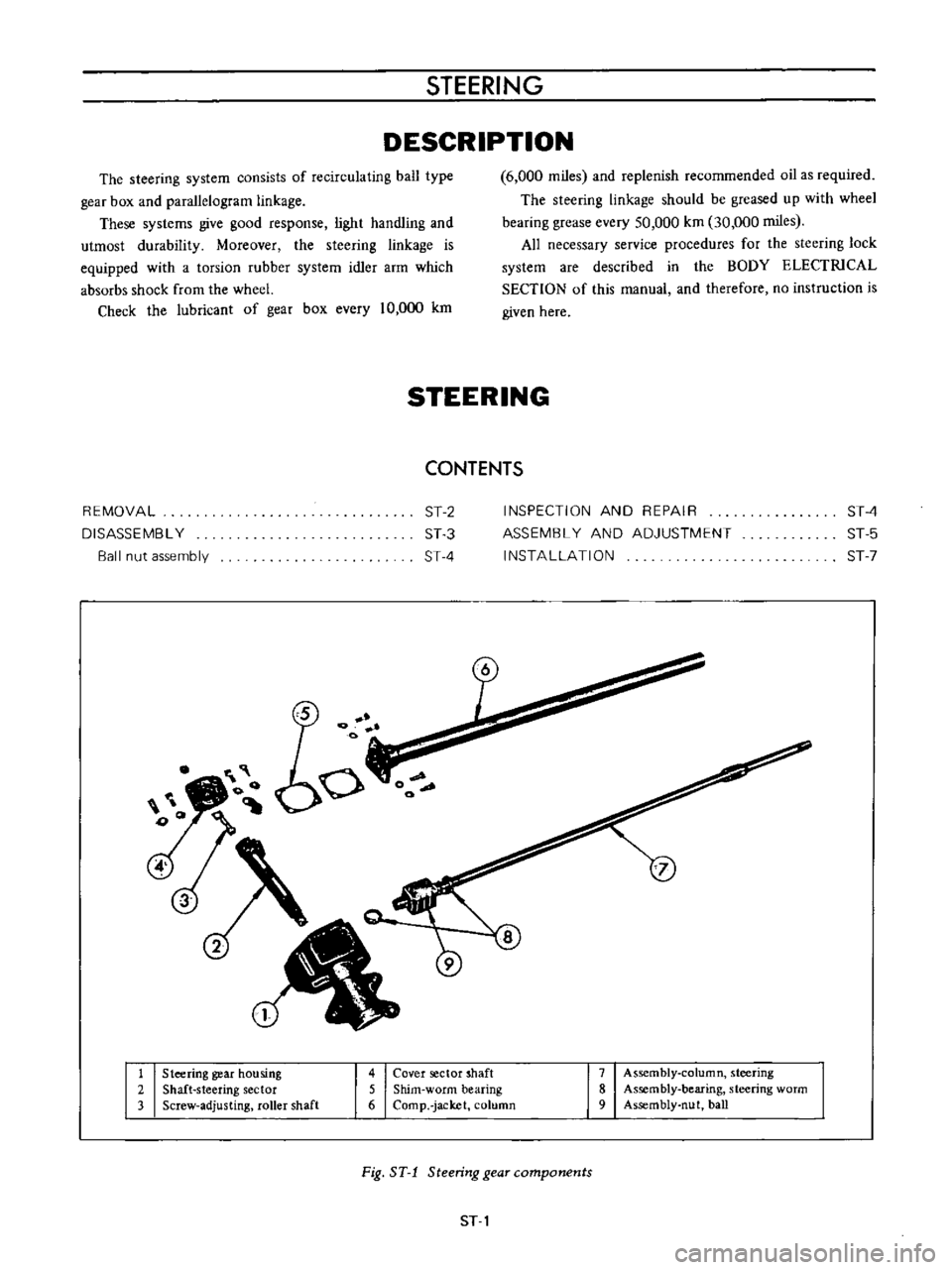
1
Steering
gear
housing
2
Shaft
steering
sector
3
Screw
adjusting
roller
shaft
4
Cover
sector
shaft
5
Shim
worm
bearing
6
Comp
jacket
column
7
Assembly
column
steering
8
Assembly
bearing
steering
worm
9
Assembly
nut
ball
Fig
ST
1
Steering
gear
components
ST
1
Page 162 of 513
Iii
I
o
t
I
I
CHASSIS
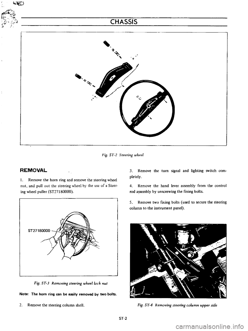
Fig
ST
2
Steering
wheel
REMOVAL
1
Remove
the
horn
ring
and
remove
the
steering
wheel
nut
and
pull
out
the
steering
wheel
by
the
use
of
a
Steer
ing
wheel
puller
ST27180000
3
Remove
the
turn
signal
and
lighting
switch
com
pletely
4
Remove
the
hand
lever
assembly
from
the
control
rod
assembly
by
unscrewing
the
fIxing
bolts
5
Remove
two
fIxing
bolts
used
to
secure
the
steering
column
to
the
instrument
panel
ST27180000
Fig
ST
3
Removing
steering
wheel
lock
nut
Note
The
horn
ring
can
be
easily
removed
by
two
bolts
2
Remove
the
steering
column
shell
Fig
ST
4
Removing
steering
column
upper
side
ST
2
Page 181 of 513
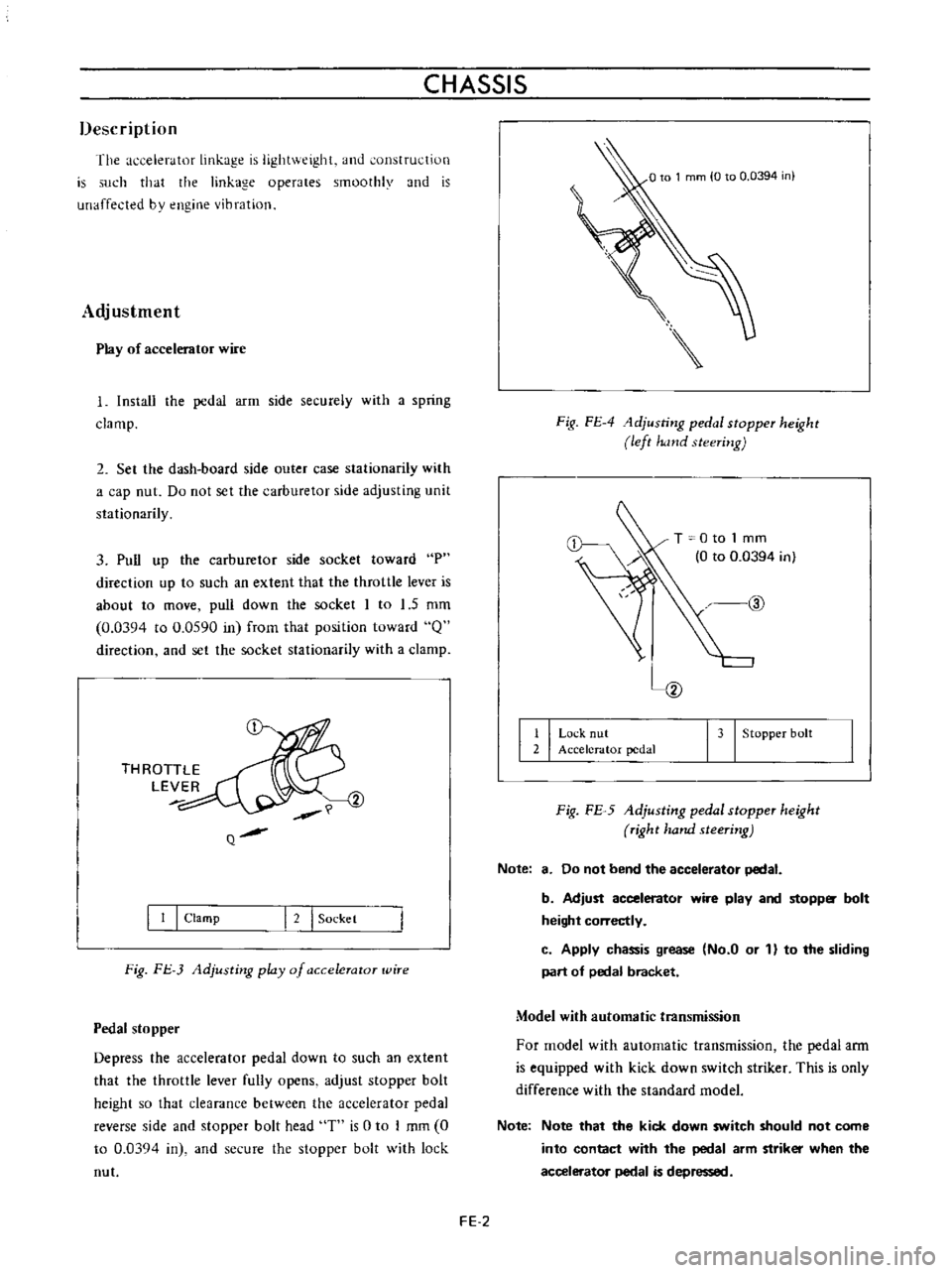
CHASSIS
Description
The
accelerator
linkage
is
lightv
eighL
and
onstfuction
is
such
that
the
linkage
operates
smoothly
and
is
unaffected
bv
engine
vibration
Adjustment
Play
of
accelerator
wire
I
Install
the
pedal
arm
side
securely
with
a
spring
clamp
2
Set
the
dash
board
side
Quter
case
stationarily
with
a
cap
nut
Do
not
set
the
carburetor
side
adjusting
unit
stationarily
3
Pull
up
the
carburetor
side
socket
toward
P
direction
up
to
such
an
extent
that
the
throttle
lever
is
about
to
move
pull
down
the
socket
I
to
1
5
mm
0
0394
to
0
0590
in
frorn
that
position
toward
Q
direction
and
set
the
socket
stationarily
with
a
clamp
THROTTLE
LEVER
Q
I
I
I
Clamp
I
2
I
Sockel
Fig
FJ
3
Adjusting
play
of
a
ccelerator
wire
Pedal
stopper
Depress
the
accelerator
pedal
down
to
such
an
extent
that
the
throttle
lever
fully
opens
adjust
stopper
bolt
height
so
that
clearance
between
the
accelerator
pedal
reverse
side
and
stopper
bolt
head
T
is
0
to
I
mm
0
to
0
03Q4
in
and
secure
the
stopper
bolt
with
lock
nut
Fig
FE
4
1djusting
pedal
stopper
height
left
hand
steering
T
0
to
1
mm
0
to
0
0394
in
@
I
I
Lo
k
nut
2
Accelerator
pedal
I
3
I
Stopper
bolt
Fig
FE
5
Adjusting
pedal
stopper
height
right
hand
steering
Note
8
Do
not
bend
the
accelerator
pedal
b
Adjust
accelerator
wire
play
and
stopp
bolt
height
correctly
c
Apply
chassis
grease
No
a
or
1
to
the
sliding
part
of
pedal
bracket
Model
with
automatic
transmission
For
model
with
automatic
transmission
the
pedal
ann
is
equipped
with
kick
down
switch
striker
This
is
only
difference
with
the
standard
model
Note
Note
that
the
kick
down
switch
should
not
come
into
contact
with
the
pedal
arm
striker
when
the
accelerator
pedal
is
depressed
FE
2
Page 213 of 513
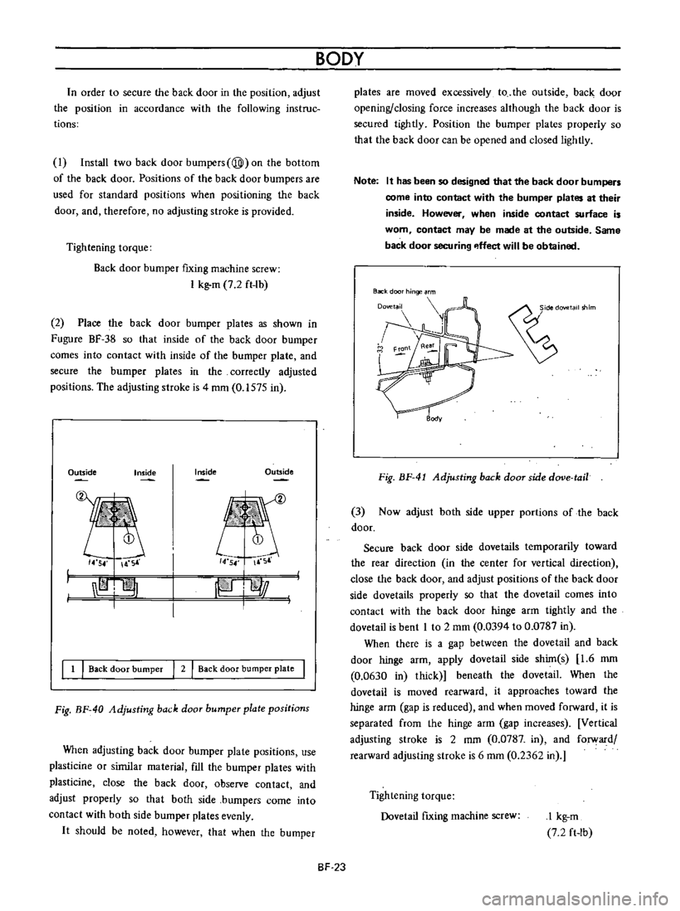
n
order
to
secure
the
back
door
in
the
position
adjust
the
position
in
accordance
with
the
following
instruc
tions
I
Install
two
back
door
bumpers
@
on
the
bottom
of
the
back
door
Positions
of
the
back
door
bumpers
are
used
for
standard
positions
when
positioning
the
back
door
and
therefore
no
adjusting
stroke
is
provided
Tightening
torque
Back
door
bumper
fixing
machine
screw
I
kg
m
7
2
ft
lb
2
Place
the
back
door
bumper
plates
as
shown
in
Fugure
BF
38
so
that
inside
of
the
back
door
bumper
comes
into
contact
with
inside
of
the
bumper
plate
and
secure
the
bumper
plates
in
the
correctly
adjusted
positions
The
adjusting
stroke
is
4
mm
0
1575
in
Outside
Inside
Outside
Inside
14
54
A
S
14
54
F
r
I
I
jpiJ
l
l
j
I
1
I
Back
door
bumper
I
2
I
Back
door
bumper
plate
I
Fig
BF
40
Adjusting
back
door
bumper
plate
positions
When
adjusting
back
door
burnper
plate
positions
use
plasticine
or
sirnilar
material
fIll
the
bumper
plates
with
plasticine
close
the
back
door
observe
contact
and
adjust
properly
so
that
both
side
bumpers
come
into
contact
with
both
side
bumper
plates
evenly
It
should
be
noted
however
that
when
the
bumper
BODY
BF
23
plates
are
moved
excessively
to
the
outside
back
door
opening
closing
force
increases
although
the
back
door
is
secured
tightly
Position
the
bumper
plates
properly
so
that
the
back
door
can
be
opened
and
closed
lightly
Note
It
has
been
so
designed
that
the
back
door
bumpers
come
into
contact
with
the
bumper
plates
at
their
inside
However
when
inside
contact
surface
is
worn
contact
may
be
made
at
the
outside
Same
back
door
securing
p
ffect
will
be
obtained
Back
door
hinge
rm
Fig
BF
41
Adjusting
back
door
side
dove
tail
3
Now
adjust
both
side
upper
portions
of
the
back
door
Secure
back
door
side
dovetails
temporarily
toward
the
rear
direction
in
the
center
for
vertical
direction
close
the
back
door
and
adjust
positions
of
the
back
door
side
dovetails
properly
so
that
the
dovetail
comes
into
contact
with
the
back
door
hinge
arm
tightly
and
the
dovetail
is
bent
I
to
2
mm
0
0394
to
0
0787
in
When
there
is
a
gap
between
the
dovetail
and
back
door
hinge
arm
apply
dovetail
side
shim
s
1
6
mm
0
0630
in
thick
beneath
the
dovetail
When
the
dovetail
is
moved
rearward
it
approaches
toward
the
hinge
arm
gap
is
reduced
and
when
moved
forward
it
is
separated
from
the
hinge
arrn
gap
increases
Vertical
adjusting
stroke
is
2
mm
0
0787
in
and
forward
rearward
adjusting
stroke
is
6
mm
0
2362
in
Tightening
torque
Dovetail
fIxing
machine
screw
I
kg
m
7
2
ft
Ib