fuse DATSUN PICK-UP 1977 Service Manual
[x] Cancel search | Manufacturer: DATSUN, Model Year: 1977, Model line: PICK-UP, Model: DATSUN PICK-UP 1977Pages: 537, PDF Size: 35.48 MB
Page 29 of 537
OPERATI
NG
PRESSURE
OF
BOOST
CONTROLLED
DECELERATION
DEVICE
B
C
D
D
ADJUSTMENT
CHECKING
a
C
D
D
CIRCUIT
WITH
FUNCTION
TEST
CONNECTOR
Manual
transmission
models
I
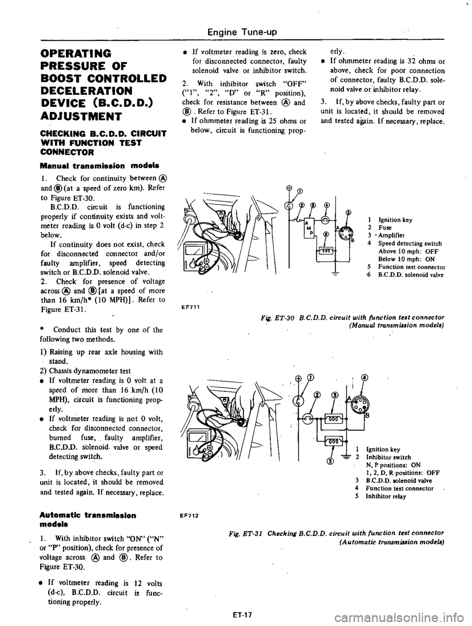
Check
for
continuity
between
@
and@
at
a
speed
of
zero
km
Refer
to
Figure
ET
30
B
C
D
D
circuit
is
functioning
properly
if
continuity
exists
and
volt
meter
reading
is
0
volt
d
c
in
step
2
below
If
continuity
does
not
exist
check
for
disconnected
connector
and
or
faulty
amplifier
speed
detecting
switch
or
B
C
D
D
solenoid
valve
2
Check
for
presence
of
voltage
across
@
and
@
at
a
speed
of
more
than
16
km
h
10
MPH
Refer
to
Figure
ET
31
Conduct
this
test
by
one
of
the
following
two
methods
i
Raising
up
rear
axle
housing
with
stand
2
Chassis
dynamometer
test
If
voltmeter
reading
is
0
volt
at
a
speed
of
more
than
16
km
h
10
MPH
circuit
is
functioning
prop
erly
If
voltmeter
reading
is
not
0
volt
check
for
disconnected
connector
burned
fuse
faulty
amplifier
B
C
D
D
solenoid
valve
or
speed
detecting
switch
3
If
by
above
checks
faulty
part
or
unit
is
located
it
should
be
removed
and
tested
again
If
necessary
replace
Automatic
transmission
models
I
With
inhibitor
switch
ON
UN
or
P
position
check
for
presence
of
voltage
across
@
and
@
Refer
to
Figure
ET
30
If
voltmeter
reading
is
12
volts
d
c
B
C
D
D
circuit
is
func
tioning
properly
Engine
Tune
up
If
voltmeter
reading
is
zero
check
for
disconnected
connector
faulty
solenoid
valve
or
inhibitor
switch
erly
If
ohmmeter
reading
is
32
ohms
or
above
check
for
poor
connection
of
connector
faulty
B
C
D
D
sole
noid
valve
or
inhibitor
relay
3
If
by
above
checks
faulty
part
or
unit
is
located
it
should
be
removed
and
tested
again
If
necessary
replace
2
With
inhibitor
switch
OFF
41
2
D
or
R
position
check
for
resistance
between
@
and
@
Refer
to
Figure
ET
31
If
ohmmeter
reading
is
25
ohms
or
below
circuit
is
functioning
prop
l
E
r
1
Ignition
key
2
Fuse
3
Amplifier
4
Speed
detecting
switch
Above
10
mph
OFF
Below
10
mph
ON
5
Function
test
connector
6
B
C
D
D
solenoid
valve
EF711
Fig
ET
30
B
C
D
D
circuit
with
function
tedconnectoT
Manual
transmission
modela
@
1
Ignition
key
2
Inhibitor
switch
N
P
positions
ON
I
2
D
R
positions
OFF
3
D
C
D
D
solenoid
valve
4
Function
test
connector
5
Inhibitor
relay
EF712
Fig
ET
31
Checking
B
C
D
D
circuit
with
function
tf
st
connf
ctor
Automatic
transmiMion
modtla
ET
17
Page 32 of 537
r
CHECKING
B
C
D
D
SOLENOID
VALVE
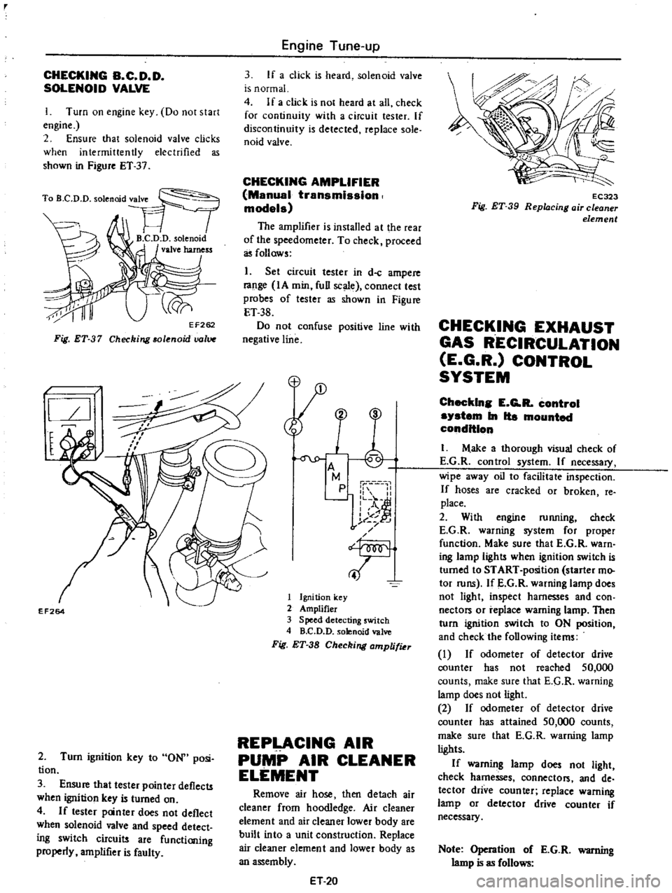
I
Turn
on
engine
key
Do
not
start
engine
2
Ensure
that
solenoid
valve
clicks
when
intermittently
electrified
as
shown
in
Figure
ET
37
Fig
ET
37
Checking
solenoid
uolV
l
I
l
EF264
2
Turn
ignition
key
to
ON
posi
tion
3
Ensure
that
tester
pointer
deflects
when
ignition
key
is
turned
on
4
If
tester
panter
does
not
deflect
when
solenoid
valve
and
speed
detect
ing
switch
circuits
are
functioning
properly
amplifier
is
faulty
Engine
Tune
up
3
If
a
click
is
heard
solenoid
valve
is
normal
4
If
a
click
is
not
heard
at
all
check
for
continuity
with
a
circuit
tester
If
discontinuity
is
detected
replace
sole
naid
valve
CHECKING
AMPLIFIER
Manual
transmission
models
The
amplifier
is
installed
at
the
rear
of
the
speedometer
To
check
proceed
as
follows
1
Set
circuit
tester
in
d
c
ampere
range
IA
min
full
scale
connect
test
probes
of
tester
as
shown
in
Figure
ET
38
Do
not
confuse
positive
line
with
negative
line
M
p
1
II
L
o
A
I
of
j
t
J
f
T
1
Ignition
key
2
Amplifier
3
Speed
detecting
switch
4
B
C
D
D
solenoid
valve
Fig
ET
38
Checking
amplifiu
REPLACING
AIR
PUMP
AIR
CLEANER
ELEMENT
Remove
air
hose
then
detach
air
cleaner
from
hoodledge
Air
cleaner
element
and
air
cleaner
lower
body
are
built
into
a
unit
construction
Replace
air
cleaner
element
and
lower
body
as
an
assembly
ET
20
EC323
Fig
ET
39
Repl4cing
air
cleaner
element
CHECKING
EXHAUST
GAS
RECIRCULATION
E
G
R
CONTROL
SYSTEM
Checkln
E
G
R
control
system
In
Ita
mounted
condition
I
M
ake
a
thorough
visual
check
of
E
G
R
control
system
If
necessary
wipe
away
oil
to
facilitate
inspection
If
hoses
are
cracked
or
broken
fe
place
2
With
engine
running
check
E
G
R
warning
system
for
proper
function
Make
sure
that
E
G
R
warn
ing
lamp
light
when
ignition
switch
is
turned
to
START
position
starter
mo
tor
runs
If
E
G
R
warning
lamp
does
not
light
inspect
harnesses
and
con
nectors
or
replace
warning
lamp
Then
turn
ignition
switch
to
ON
position
and
check
the
following
items
I
If
odometer
of
detector
drive
counter
has
not
reached
50
000
counts
make
sure
that
E
G
R
warning
lamp
does
not
light
2
If
odometer
of
detector
drive
counter
has
attained
50
000
counts
make
sure
that
E
G
R
warning
lamp
lights
If
warning
lamp
does
not
light
check
harnesses
connector
and
de
tector
drive
counter
replace
warning
lamp
or
detector
drive
counter
if
necessary
Note
Operation
of
E
G
R
warning
lamp
is
as
follows
Page 121 of 537
When
throttle
valve
is
opened
fur
ther
locking
arm
is
detached
from
secondary
throttle
arm
permitting
see
ondary
system
to
start
operation
Linkage
between
primary
and
see
ondary
throttles
will
function
properly
if
distance
between
throttle
valve
and
inner
wall
of
throttle
chamber
is
74
mm
0
291
in
Adjustment
is
made
by
bending
connecting
link
I
L
l
1
4
CAl
Secondary
prm
ary
I
Jl
I
7
t
@
1
Roller
4
Adjust
plate
2
Connecting
lever
5
Throttle
c
amber
3
Return
plate
6
Throttle
valve
Fig
EF
48
Adjusting
interlock
opening
DASH
POT
1
Idling
speed
of
engine
and
mix
ture
must
be
well
tuned
up
and
engine
sufficiently
warm
2
Turn
throttle
valve
by
hand
and
read
engine
speed
when
dash
pot
just
touches
stopper
lever
3
Adjust
position
of
dash
pot
by
turning
nut
until
engine
speed
is
in
the
specified
range
Specified
engine
speed
Manual
transmission
1
900
to
2
100
rpm
Automatic
transmission
1
650
to
1
850
rpm
4
Tighten
lock
nuts
5
Make
sure
that
engine
speed
drops
smoothly
from
2
000
to
1
000
rpm
in
about
three
seconds
Engine
Fuel
Fig
EF
49
Adjusting
dash
pot
ACCELERATING
PUMP
I
Visually
inspect
accelerating
pump
cover
for
any
sign
of
fuel
leaks
2
If
fuel
leaks
are
found
check
gasket
and
replace
if
necessary
ANTI
DIESELING
SOLENOID
VALVE
If
engine
does
not
stop
when
igni
tion
switch
is
turned
off
this
indicates
that
a
striking
closed
solenoid
valve
is
shutting
off
supply
of
fuel
to
engine
If
harness
is
in
good
condition
replace
solencid
valve
as
a
unit
Notes
a
Tightening
torque
is
1
8
to
3
5
kg
m
13
to
25
ft
Ib
b
After
replacement
star
engine
and
check
to
be
sure
that
fuel
is
not
leaking
and
that
anti
dieseling
sol
noid
is
in
good
condition
B
C
D
D
CIRCUIT
WITH
FUNCTION
TEST
CONNECTOR
Caution
Do
not
attach
test
leads
of
a
circuit
tester
to
those
other
than
designated
Refer
to
Figure
EF
50
Menuel
trensmlsslon
models
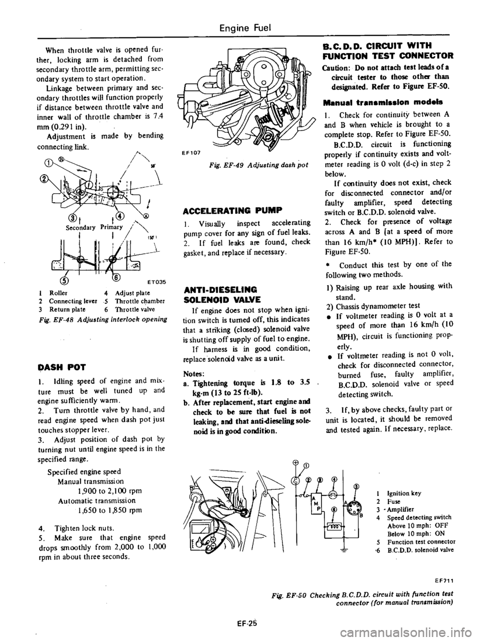
I
Check
for
continuity
between
A
and
B
when
vehicle
is
brought
to
a
complete
stop
Refer
to
Figure
EF
50
B
C
D
D
circuit
is
functioning
properly
if
continuity
exists
and
volt
meter
reading
is
0
volt
d
c
in
step
2
below
If
continuity
does
not
exist
check
for
disconnected
connector
and
or
faulty
amplifier
speed
detecting
switch
or
B
C
D
D
solenoid
valve
2
Check
for
presence
of
voltage
across
A
and
B
at
a
speed
of
more
than
16
km
h
10
MPH
Refer
to
Figure
EF
50
Conduct
this
test
by
one
of
the
following
two
methods
I
Raising
up
rear
axle
housing
with
stand
2
Chassis
dynamometer
test
If
voltmeter
reading
is
0
volt
at
a
speed
of
more
than
16
km
h
10
MPH
circuit
is
functioning
prop
erly
If
voltmeter
reading
is
not
0
volt
check
for
disconnected
connector
burned
fuse
faulty
amplifier
B
C
D
D
solenoid
valve
or
speed
detecting
switch
3
If
by
above
checks
faulty
part
or
unit
is
located
it
should
be
removed
and
tested
again
If
necessary
replace
1
P4
11
0
8
l
1
Ignition
Icey
2
Fuse
3
Amplifier
4
Speed
detecting
switch
Above
10
mph
OFF
Below
10
mph
ON
5
Function
test
connector
6
B
C
D
D
solenoid
valve
EF711
Fig
EF
50
Checking
B
C
D
D
circuit
with
function
test
connector
for
manual
transmission
EF
25
Page 125 of 537
I
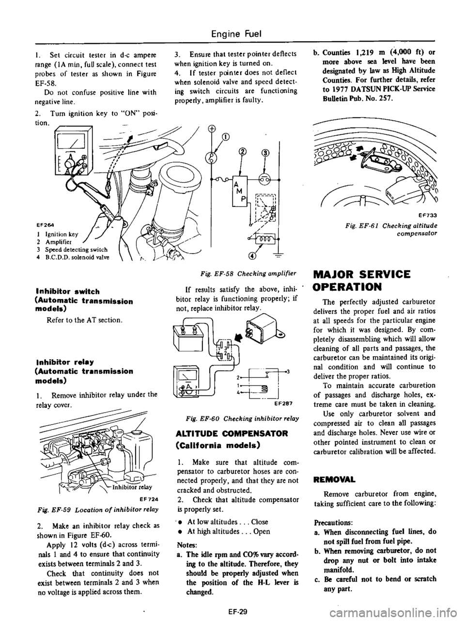
Set
circuit
tester
in
d
c
ampere
range
IA
min
fuU
scale
connect
test
probes
of
tester
as
shown
in
Figure
EF
58
Do
not
confuse
positive
line
with
negative
line
2
Turn
ignition
key
to
ON
posi
tion
I
t
EF264
1
Ignition
key
2
Amplifier
3
Speed
detecting
switch
4
B
C
D
D
solenoid
valve
Inhibitor
switch
Automatic
transmission
models
Refer
to
the
AT
section
Inhibitor
relay
Automatic
transmission
models
Inhibitor
relay
EF724
Fig
EF
59
Location
of
inhibitor
relay
2
Make
an
inhibitor
relay
check
as
shown
in
Figure
EF
60
Apply
12
volts
d
c
across
termi
nals
1
and
4
to
ensure
that
continuity
exists
between
terminals
2
and
3
Check
that
continuity
does
not
exist
between
terminals
2
and
3
when
no
voltage
is
applied
across
them
Engine
Fuel
3
Ensure
that
tester
pointer
deflects
when
ignition
key
is
turned
on
4
If
tester
pointer
does
not
deflect
when
solenoid
valve
and
speed
detect
ing
switch
circuits
are
functioning
properly
amplifier
is
faulty
Fig
EF
58
Checking
amplifier
If
results
satisfy
the
above
inhi
bitor
relay
is
functioning
properly
if
not
replace
inhibitor
relay
it
@
j
l
j
4
L
I
44
11
oJ
EF287
Fig
EF
60
Checking
inhibitor
relay
ALTITUDE
COMPENSATOR
California
models
Make
sure
that
altitude
com
pensator
to
carburetor
hoses
are
con
nected
properly
and
that
they
are
not
cracked
and
obstructed
2
Check
that
altitude
compensator
is
properly
set
At
low
altitudes
At
high
altitudes
Notes
a
The
idle
Pm
and
CO
vary
accord
ing
to
the
altitude
Therefore
they
should
be
properly
adjusted
when
the
position
of
the
H
L
lever
is
changed
Close
Open
EF
29
b
Counties
1
219
m
4
000
ft
or
more
above
sea
level
have
been
designated
by
law
as
High
Altitude
Counties
For
further
details
refer
to
1977
DATSUN
PICK
UP
Service
BuUetin
Pub
No
257
Q0
1
v
EF733
Fig
EF
61
Checking
altitude
compensator
MAJOR
SERVICE
OPERATION
The
perfectly
adjusted
carburetor
delivers
the
proper
fuel
and
air
ratios
at
all
speeds
for
the
particular
engine
for
which
it
was
designed
By
com
pletely
disassembling
which
will
allow
deaning
of
all
parts
and
passages
the
carburetor
can
be
maintained
its
origi
nal
condition
and
will
continue
to
deliver
the
proper
ratios
To
maintain
accurate
carburetion
of
passages
and
discharge
holes
ex
treme
care
must
be
taken
in
cleaning
Use
only
carburetor
solvent
and
compressed
air
to
clean
all
passages
and
discharge
holes
Never
use
wire
or
other
pointed
instrument
to
clean
or
carburetor
calibration
will
be
affected
REMOVAL
Remove
carburetor
from
engine
taking
sufficient
care
to
the
following
Precautions
a
When
disconnecting
fuel
lines
do
not
spill
fuel
from
fuel
pipe
b
When
removing
carburetor
do
not
drop
any
nut
or
bolt
into
intake
manifold
c
Be
careful
not
to
bend
or
scratch
any
part
Page 148 of 537
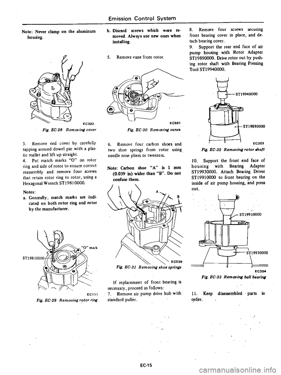
Note
Never
clamp
on
the
aluminum
housing
EC302
Fig
EC
28
Removing
cover
3
Remove
end
cover
by
carefully
tapping
around
dowel
pin
with
a
plas
tic
mallet
and
lift
up
straight
4
Put
match
marks
0
on
rotor
ring
and
side
of
rotor
to
ensure
correct
reassembly
and
remove
four
screws
that
retain
rotor
ring
to
rotor
using
a
Hexagonal
Wrench
STl9810000
Notes
a
Generally
match
marks
are
indi
cated
on
both
rotor
ring
and
rotor
by
the
manufacturer
ECll1
Fig
EC
29
Removing
rotor
ring
Emission
Control
System
b
Discard
screws
which
were
re
moved
Always
use
new
ones
when
installing
5
Remove
vane
from
rotor
EC661
Fig
EC
30
Remooing
vanes
6
Remove
four
carbon
shoes
and
two
shoe
springs
from
rotor
using
needle
nose
pliers
or
tweezers
Note
Carbon
shoe
A
0
039
in
wider
than
confuse
them
is
I
mm
B
Do
not
If
replacement
of
front
bearing
is
necessary
proceed
as
follows
7
Remove
air
pump
drive
hub
with
standard
puller
EC
15
8
Remove
four
screws
securing
front
bearing
cover
in
place
and
de
tach
bearing
cover
9
Support
the
rear
end
face
of
air
pump
housing
with
Rotor
Adapter
STl9890000
Drive
rotor
out
by
push
ing
rotor
shaft
with
Bearing
Pressing
Tool
STl9940000
STl9940000
1Ul
STl9890000
I
I
EC303
Fig
EC
32
Removing
rotor
shaft
10
Support
the
front
end
face
of
housing
with
Bearing
Adapter
STl9930000
Attach
Bearing
Driver
STl9910000
to
front
bearing
on
the
inside
of
air
pump
housing
iuid
press
out
ll
I
I
STl9910000
i
L
9930000
J
1
EC304
Fig
EC
33
Remouing
ball
bearing
11
Keep
disassembled
parts
in
rder
Page 150 of 537
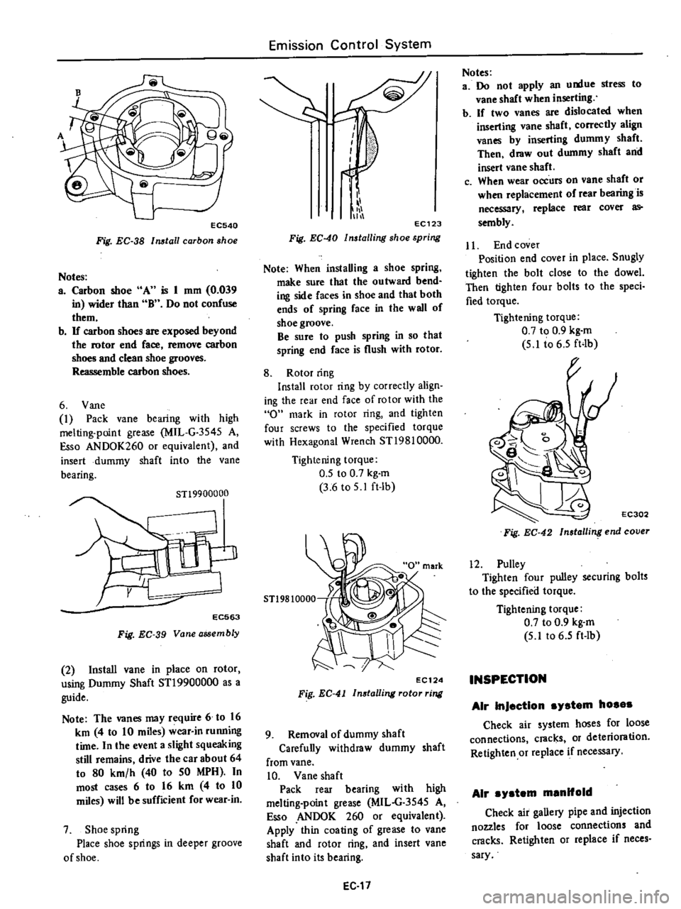
EC540
Fig
EC
38
Install
carbon
shoe
Notes
a
Carbon
shoe
A
is
1
mm
0
039
in
wider
than
B
Do
not
confuse
them
b
If
carbon
shoes
are
exposed
beyond
the
rotor
end
face
remove
carbon
shoes
and
clean
shoe
grooves
Reassemble
carbon
shoes
6
Vane
1
Pack
vane
bearing
with
high
melting
point
grease
MIL
G
3545
A
Esso
ANDOK260
or
equivalent
and
insert
dummy
shaft
into
the
Vane
bearing
STl9900000
EC563
Fig
EC
39
Vane
assembly
2
Install
vane
in
place
on
rotor
using
Dummy
Shaft
STl9900000
as
a
guide
Note
The
vanes
may
require
6
to
16
km
4
to
10
miles
wear
in
running
time
In
the
event
a
slight
squeaking
still
remains
drive
the
car
about
64
to
80
km
h
40
to
50
MPH
In
most
cases
6
to
16
km
4
to
10
miles
will
be
sufficient
for
wear
in
7
Shoe
spring
Place
shoe
springs
in
deeper
groove
of
shoe
Emission
Control
System
i
111
11
EC123
Fig
EC
40
Installing
shoe
spring
Note
When
instaUing
a
shoe
spring
make
sure
that
the
outward
bend
ing
side
faces
in
shoe
and
that
both
ends
of
spring
face
in
the
wall
of
shoe
groove
Be
sure
to
push
spring
in
so
that
spring
end
face
is
flush
with
rotor
8
Rotor
ring
Install
rotor
ring
by
correctly
align
ing
the
rear
end
face
of
rotor
with
the
0
mark
in
rotor
ring
and
tighten
four
screws
to
the
specified
torque
with
Hexagonal
Wrench
ST19810000
Tightening
torque
0
5
to
0
7
kg
m
3
6
to
5
1
ft
lb
5T19810000
EC124
Fig
EC
41
In8talling
rotor
ring
9
Removal
of
dummy
shaft
Carefuny
withdraw
dummy
shaft
from
vane
10
Vane
shaft
Pack
rear
bearing
with
high
melting
point
grease
MIL
G
3545
A
so
ANDOK
260
or
equivalent
Apply
thin
coating
of
grease
to
vane
shaft
and
rotor
ring
and
insert
vane
shaft
into
its
bearing
EC
17
Notes
a
Do
not
apply
an
u
tue
stress
to
vane
shaft
when
inserting
b
If
two
vanes
are
dislocated
when
inserting
vane
shaft
correctly
align
vanes
by
inserting
dummy
shaft
Then
draw
out
dummy
shaft
and
insert
vane
shaft
c
When
wear
occurs
on
vane
shaft
or
when
replacement
of
rear
bearing
is
necessary
replace
rear
cover
as
sembly
Jl
End
cover
Position
end
cover
in
place
Snugly
tighten
the
bolt
close
to
the
dowel
Then
tighten
four
bolts
to
the
speci
fied
torque
Tightening
torque
0
7
to
0
9
kg
m
5
1
t06
5
ft4b
EC302
Fig
EC
42
Insla
ling
end
cover
12
Pulley
Tighten
four
pulley
securing
bolts
to
the
specified
torque
Tightening
torque
0
7
to
0
9
kg
m
5
lt06
5
ft
lb
INSPECTION
Air
InJection
system
hosas
Check
air
system
hoses
for
loose
connections
cracks
or
deterioration
Retighten
or
replace
if
necessary
Air
ystem
manifold
Check
air
gaUery
pipe
and
injection
nozzles
for
loose
connections
and
cracks
Retighten
or
replace
if
neces
sary
Page 156 of 537
1
1
I
I
I
1
v
v
I
I
I
I
I
I
I
I
I
I
I
I
I
I
I
I
I
I
I
I
I
L
0
I
Magnet
coil
Detector
drive
counter
REMOVAL
AND
INSTALLATION
Remove
air
cleaner
before
removing
E
G
R
control
system
For
removal
and
installation
of
air
cleaner
refer
to
Air
Cleaner
section
Page
EF
S
Removal
I
E
G
R
control
valve
After
removing
the
following
parts
the
E
G
R
controi
valve
can
be
dis
mounted
Vacuum
hose
thermal
vacuum
valve
to
E
G
R
control
valve
E
G
R
control
valve
mounting
nut
Note
To
remove
vacuum
hose
flat
ten
clip
connecting
vacuum
hose
to
E
G
R
control
valve
and
pull
the
hose
off
with
hand
Emission
Control
System
Ignition
switch
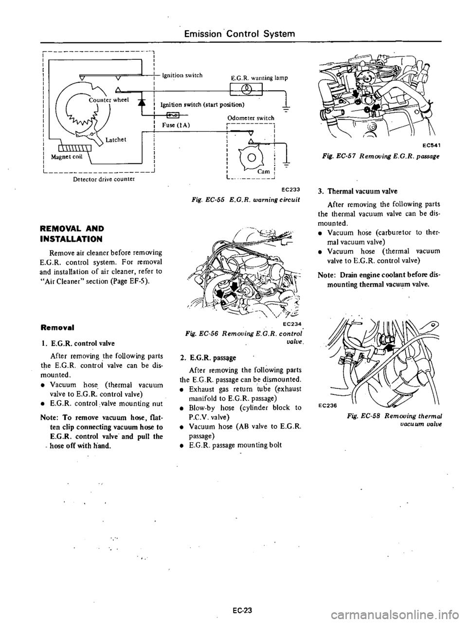
E
G
R
warning
lamp
f
1
Ignition
switch
start
position
Fuse
1
A
Odometer
switch
r
I
I
I
I
v
I
I
I
i
lQ
U
1
mi
L
J
EC233
Fig
EC
55
E
G
R
warning
circuit
EC234
Fig
EC
56
Removing
KG
R
control
valve
2
E
G
R
pass
ge
After
removing
the
following
parts
the
E
G
R
passage
can
be
dismounted
Exhaust
gas
return
tube
exhaust
manifold
to
E
G
R
passage
B1ow
by
hose
cylinder
block
to
P
C
v
valve
Vacuum
hose
AB
valve
to
E
G
R
passage
E
G
R
passage
mounting
bolt
EC
23
EC541
Fig
EC
57
Removing
E
G
R
passage
3
Thermal
vacuum
valve
After
removing
the
following
parts
the
thermal
vacuum
valve
can
be
dis
mounted
Vacuum
hose
carburetor
to
ther
mal
vacuum
valve
Vacuum
hose
thermal
vacuum
valve
to
E
G
R
control
valve
Note
Drain
engine
coolant
before
dis
mounting
thermal
vacu
m
valve
Fig
EC
58
Removing
thermal
vacu
um
valve
Page 181 of 537
Engine
Electrical
System
B
v
W
WR
WL
L2
VOLTAGE
REGULATOR
co
LW
I
P
B
r
FUSIBLE
LINK
m
I
WLI
LW
cJ
I
B
t
EARTH
POINT
m
WR
WR
CHARGE
g
00
WARNING
lAMP
00000
Equipped
with
cooler
I
I
I
I
TjT
m
CLB
W
WB
B
YWR
I
I
I
I
1
W
B
rn
ALTERNATOR
I
l
LW
BW
j
J
M
IG
I
W
BwtIl
IGNITION
SWITCH
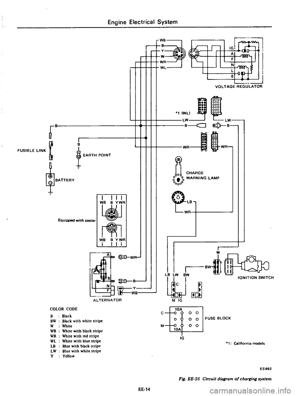
COLOR
CODE
B
Black
OW
Black
with
white
stripe
W
White
WB
White
with
black
stripe
WR
White
with
red
stripe
WL
White
with
blue
stripe
LO
Blue
with
black
stripe
LW
Blue
with
white
stripe
Y
Yellow
lOA
C
o
0
0
0
o
0
0
FUSE
BLOCK
M
0
0
0
lOA
Ii
California
models
E
E492
Fig
EE
25
Circuit
diagram
of
charging
lfY
t
m
EE
14
Page 188 of 537
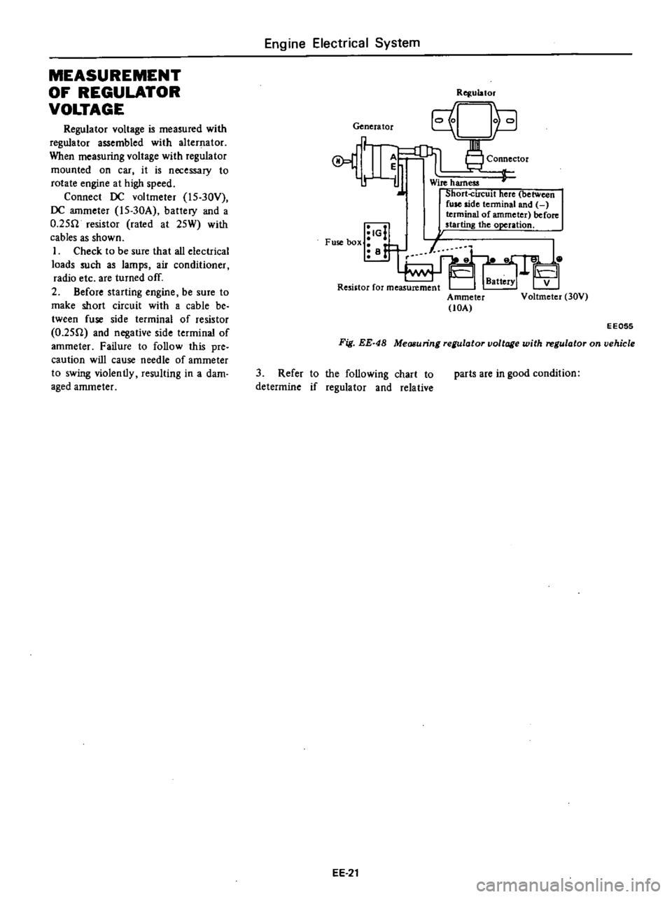
MEASUREMENT
OF
REGULATOR
VOLTAGE
Regulator
voltage
is
measured
with
regulator
assembled
with
alternator
When
measuring
voltage
with
regulator
mounted
on
car
it
is
necessary
to
rotate
engine
at
high
speed
Connect
DC
voltmeter
l5
30Y
DC
ammeter
l5
30A
battery
and
a
O
25fl
resistor
rated
at
25W
with
cables
as
shown
I
Check
to
be
sure
that
all
electrical
loads
such
as
lamps
air
conditioner
radio
etc
are
turned
off
2
Before
starting
engine
be
sure
to
make
short
circuit
with
a
cable
be
tween
fuse
side
terminal
of
resistor
O
25fl
and
negative
side
terminal
of
ammeter
Failure
to
follow
this
pre
caution
will
cause
needle
of
ammeter
to
swing
violently
resulting
in
a
dam
aged
ammeter
Engine
Electrical
System
Genera
tor
A
r
iJ
IG
Fuse
box
i
B
Rqulator
Connector
Wire
harness
Short
circuit
here
between
fuse
side
tenninal
and
terminal
of
ammeter
before
starting
the
operation
Ammeter
lOA
V
Voltmeter
30V
EE055
Fig
EE
48
Measuring
regulator
voltage
with
regulator
on
vehicle
3
Refer
to
the
following
chart
to
determine
if
regulator
and
relative
EE
21
parts
are
in
good
condition
Page 204 of 537
Engine
Electrical
System
Transistor
ignition
unit
r
1
Power
switching
circuit
Duty
control
circuit
To
starter
To
distributor
Ba
ttery
Ignition
coil
1
Spark
timing
1
Signal
mom
toring
circuit
Lock
j
preven
ling
circuit
nm
Distributor
EE437
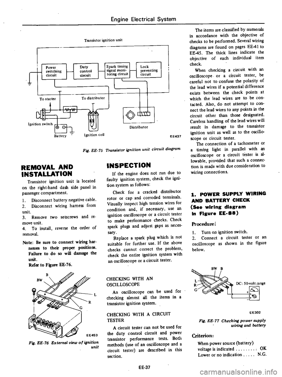
Fig
EE
75
Transistor
ignition
unit
circuit
diagram
REMOVAL
AND
INSTALLATION
Transistor
ignition
unit
is
located
on
the
right
hand
dash
side
panel
in
passenger
compartment
Disconnect
battery
negative
cable
2
Disconnect
wiring
harness
from
unit
3
Remove
two
setscrews
and
te
move
unit
4
To
install
reverse
the
order
of
removal
Note
Be
sure
to
connect
wiring
har
nesses
to
their
proper
positio
Failure
to
do
so
will
damage
the
unit
Refer
to
Figure
EE
76
Fig
EE
76
External
view
of
ignition
unit
INSPECTION
If
the
engine
does
not
run
due
to
faulty
ignition
system
check
the
igni
tion
system
as
follows
Check
for
a
cracked
distributor
rotor
or
cap
and
corroded
tenninals
Visually
inspect
high
tension
wires
for
condition
and
if
necessary
use
an
ignition
oscilloscope
or
a
circuit
tester
to
make
performance
checks
Check
spark
plugs
and
adjust
gaps
as
neces
sary
Replace
a
spark
plug
which
is
not
suitable
for
further
use
If
the
above
checks
cannot
correct
the
problem
check
the
entire
ignition
system
with
an
oscilloscope
or
a
circuit
tester
L
CHECKING
WITH
AN
OSCILLOSCOPE
An
oscilloscope
can
be
used
for
checking
almost
all
the
items
in
a
transistor
ignition
system
CHECKING
WITH
A
CIRCUIT
TESTER
A
circuit
tester
can
not
be
used
for
the
duty
control
circuit
and
power
t18nsistor
performance
tests
Both
methods
use
of
an
oscilloscope
and
a
circuit
tester
are
described
in
this
section
EE
37
The
items
are
classified
by
numerals
in
accordance
with
the
objective
of
checks
to
be
performed
Several
wiring
diagrams
are
found
on
pages
EE
41
to
EE
45
The
thick
lines
indicate
the
objective
of
each
individual
item
check
When
checking
a
circuit
with
an
oscilloscope
or
a
circuit
tester
be
careful
not
to
confuse
the
polarity
of
the
lead
wires
if
potential
difference
exists
between
the
check
points
at
which
the
lead
wires
are
to
be
con
tacted
Also
do
not
attempt
to
con
nect
the
lead
wires
to
any
points
in
the
circuit
other
than
those
designated
Careless
handling
of
the
lead
wires
will
result
in
damage
to
the
transistor
ignition
unit
as
well
as
to
the
oscillo
scope
or
circuit
tester
The
connection
of
a
tachometer
or
a
timing
light
in
parallel
with
an
oscilloscope
or
a
circuit
tester
is
al
lowable
provided
that
such
a
connec
tion
is
made
with
due
consideration
to
wiring
connections
1
POWER
SUPPLY
WIRING
AND
BAnERY
CHECK
See
wIrIng
diagram
In
FIgure
EE
88
Procedure
I
Turn
on
ignition
switch
2
Connect
a
circuit
tester
or
an
oscilloscope
as
shown
in
the
figure
below
DC
50
volt
range
EE302
Fig
EE
77
Checking
power
supply
wiring
and
batt
ry
Criterion
When
power
source
battery
voltage
is
indicated
OK
Lower
or
no
indication
N
G