height adjustment DATSUN PICK-UP 1977 Service Manual
[x] Cancel search | Manufacturer: DATSUN, Model Year: 1977, Model line: PICK-UP, Model: DATSUN PICK-UP 1977Pages: 537, PDF Size: 35.48 MB
Page 225 of 537
l
t
tJ
I
P
o
CUll
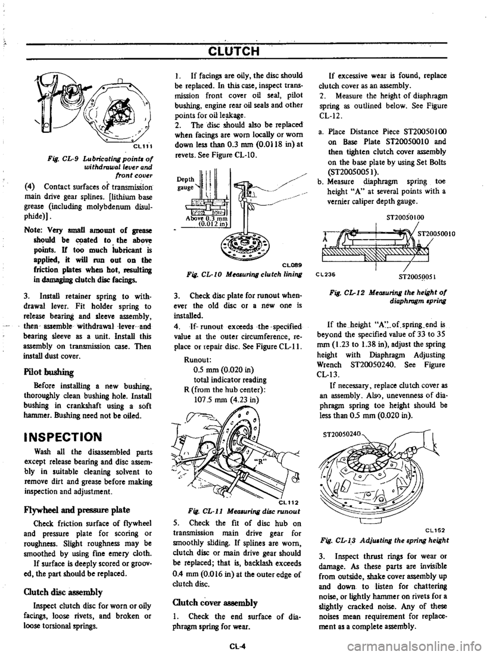
Fig
CL
9
Lubricating
poinu
of
withdrawal
lever
and
front
cover
4
Contact
surfaces
of
transmission
main
drive
gear
splines
lithium
base
grease
including
molybdenum
disul
phide
Note
Very
IIIIJllII
amount
of
grease
should
be
ated
to
the
above
points
If
too
much
iubricant
is
applied
it
will
run
out
on
the
friction
plates
when
hot
resulting
in
d
gi
dutch
disc
facings
3
Install
retainer
spring
to
with
drawal
lever
Fit
holder
spring
to
release
bearing
and
sleeve
assembly
then
assemble
withdrawal
Iever
and
bearing
sleeve
as
a
unit
Install
this
assembly
on
transmission
case
Then
install
dust
cover
Pilot
bushing
Before
installing
a
new
bushing
thoroughly
clean
bushing
hole
Install
bushing
in
crankshaft
using
a
soft
hammer
Bushing
need
not
be
oiled
INSPECTION
Wash
all
the
disassembled
parts
except
release
bearing
and
disc
assem
bly
in
suitable
cleaning
solvent
to
remove
dirt
and
grease
before
making
inspection
and
adjustment
Flywheel
and
pressure
plate
Check
friction
surface
of
flywheel
and
pressure
plate
for
scoring
or
roughness
Slight
roughness
may
be
smoothed
by
using
fme
emery
cloth
If
surface
is
deeply
scored
or
groov
ed
the
part
should
be
replaced
Clutch
disc
at
llembly
Inspect
clutch
disc
for
worn
or
oily
facings
loose
rivets
and
broken
or
loose
torsional
springs
CLUTCH
I
If
facings
are
oily
the
disc
should
be
replaced
In
this
case
inspect
trans
mission
front
cover
oil
seal
pilot
bushing
engine
rear
oil
seals
and
other
points
for
oil
leakage
2
The
disc
should
also
be
replaced
when
facings
are
worn
locally
or
worn
down
less
than
0
3
mm
0
0118
in
at
revels
See
Figure
CL
IO
DePth
ll
I
gauge
II
1
i
h
1
j1
t
f
Above
0
3
rom
10
012
in
CL089
Fig
CL
I0
Me
JIuringclutch
lining
3
Check
disc
plate
for
runout
when
ever
the
old
disc
or
a
new
one
is
installed
4
If
runoutexceeds
the
specified
value
at
the
outer
circumference
Ie
place
or
repair
disc
See
Figure
CL
II
Runou
t
0
5
mm
0
020
in
total
indicator
reading
R
from
the
hub
center
107
5
mm
4
23
in
CL112
Fig
CL
ll
MeOlUring
disc
runout
5
Check
the
fit
of
disc
hub
on
transmission
main
drive
gear
for
smoothly
sliding
If
splines
are
worn
clutch
disc
or
main
drive
gear
should
be
replaced
that
is
backlash
exceeds
0
4
mm
0
016
in
at
the
outer
edge
of
clutch
disc
Clutch
cover
assembly
I
Check
the
end
surface
of
dia
phragm
spring
for
wear
CL
4
If
excessive
wear
is
found
replace
clu
tch
cover
as
an
assembly
2
Measure
the
height
of
diaphragm
spring
as
outlined
below
See
Figure
CL
12
a
Place
Distance
Piece
ST20050100
on
Base
Plate
ST20050010
and
then
tighten
clutch
cover
assembly
on
the
base
plate
by
using
Set
Bolls
ST20050051
b
Measure
diaphragm
spring
toe
height
A
at
several
points
with
a
vernier
caliper
depth
gauge
STl0050100
rJrf
I
Tl
05001O
f
7
C
L23
STl005Q051
Fig
CL
12
Me
uring
the
height
of
diaphragm
pring
If
the
height
A
of
spring
end
is
beyond
the
specified
value
of
33
to
35
mm
1
23
to
1
38
in
adjust
the
spring
height
with
Diaphragm
Adjusting
Wrench
ST20050240
See
Figure
CL
13
If
necessary
replace
clutch
cover
as
an
assembly
Also
unevenness
of
dia
phragm
spring
toe
height
should
be
less
than
05
mm
0
020
in
ST20050240
CL152
Fig
CL
13
AdjlUting
the
spring
height
3
Inspect
thrust
rings
for
wear
or
damage
As
these
parts
are
invisible
from
outside
shake
cover
assembly
up
and
down
to
listen
for
chattering
noise
or
lightly
hammer
on
rivets
for
a
slightly
cracked
noise
Any
of
these
noises
mean
requirement
for
replace
ment
as
a
complete
assembly
Page 227 of 537
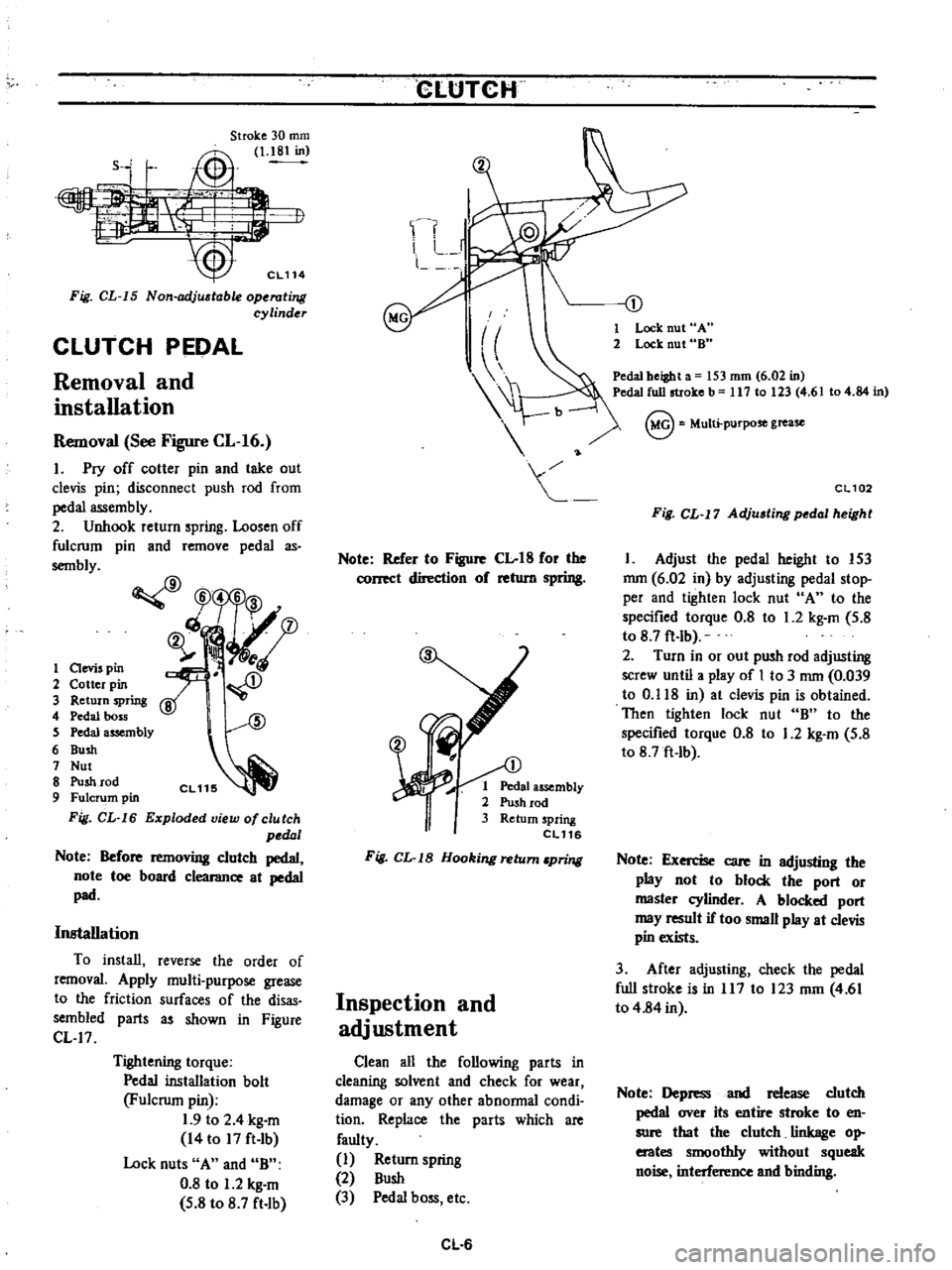
Stroke
30
mm
Jt
i
I
1
18
in
Sj
1
i
J
o
Fig
CL
15
Non
adj
table
operating
cylinder
CLUTCH
PEDAL
Removal
and
installation
Removal
See
Figure
CL
16
1
Pry
off
cotter
pin
and
take
out
clevis
pin
disconnect
push
rod
from
pedal
assembly
2
Unhook
return
spring
Loosen
off
fulcrum
pin
and
remove
pedal
as
sembly
CfJ
W5
6
3
ch
fD
ij
ll
i
A
1
aevis
pin
2
Cotter
pin
3
Return
spring
4
Pedal
boss
S
Pedal
assembly
6
Bush
7
Nut
8
Push
rod
9
Fulcrum
pin
Fig
CL
16
Exploded
view
of
clutch
pedal
Note
Before
removing
clutch
pedal
note
toe
board
clearance
at
pedal
pad
Installation
To
install
reverse
the
order
of
removal
Apply
multi
purpose
grease
to
the
friction
surfaces
of
the
disas
sembled
parts
as
shown
in
Figure
CL
17
Tightening
torque
Pedal
installation
bolt
Fulcrum
pin
1
9
to
2
4
kg
m
14
to
17
ft
Ib
Lock
nuts
A
and
B
0
8
to
1
2
kg
m
5
8
to
8
7
ft
lb
CLtJTCH
Note
Refer
to
Figure
Clot8
for
the
correct
direction
of
return
spring
1
Pedal
assembly
2
Push
rod
3
Return
spring
eL116
Fig
CL
1B
Hooking
return
pring
Inspection
and
adjustment
Clean
all
the
following
parts
in
cleaning
solvent
and
check
for
wear
damage
or
any
other
abnormal
condi
tion
Replace
the
parts
which
are
faulty
1
Return
spring
2
Bush
3
Pedal
boss
etc
CL
6
1
Lock
nut
A
2
Lock
nut
8
Pedal
beiBht
a
53
mm
6
02
in
Pedal
full
stroke
b
117
10
23
4
6
104
84
in
@
Multi
purpose
grease
CL102
Fig
CL
17
Adju
ting
pedal
height
1
Adjust
the
pedal
height
to
153
mm
6
02
in
by
adjusting
pedal
stop
per
and
tighten
lock
nut
A
to
the
specified
torque
0
8
to
1
2
kg
m
5
8
to
8
7
ft
lb
2
Turn
in
or
out
push
rod
adjusting
screw
until
a
play
of
I
to
3
mm
0
039
to
0
118
in
at
clevis
pin
is
obtained
Then
tighten
lock
nut
B
to
the
specified
torque
0
8
to
1
2
kg
m
5
8
to
8
7ft
Ib
Note
Exercise
care
in
adjusting
the
play
not
to
block
the
port
or
master
cylinder
A
blocked
port
may
result
if
too
small
play
at
clevis
pin
exists
3
After
adjusting
check
the
pedal
full
stroke
is
in
117
to
123
mm
4
61
to
4
84
in
Note
Depress
and
release
clutch
pedal
over
its
entire
stroke
to
en
sure
that
the
clutch
linkage
op
erates
smoothly
without
squeak
noise
interference
and
binding
Page 333 of 537
PROPELLER
SHAFT
DIFFERENTIAL
CARRIER
Condition
Probable
cause
Knocking
sound
during
starting
or
noise
during
coasting
on
propeller
shaft
Worn
damaged
universal
joint
Worn
sleeve
yoke
and
main
shaft
spline
Loose
propeller
shaft
installation
Loose
joint
installation
Damaged
center
bearing
or
insulator
Loose
or
missing
bolts
at
center
bearing
bracket
to
body
Scraping
noise
Dust
cover
on
sleeve
yoke
rubbing
on
transmission
rear
extension
Dust
c
ver
on
companion
flange
rubbing
on
differ
mtial
carrier
Whine
or
whistle
Damaged
center
bearing
Corrective
action
Replace
Replace
Retighten
Adjust
snap
ring
Replace
Replace
or
tighten
bolts
Straighten
out
dust
cover
to
remove
inter
ference
Replace
DIFFERENTIAL
CARRIER
TYPE
H190
CONTENTS
DESCRIPTION
REMOVAL
PRE
DISASSEMBLY
INSPECTION
DISASSEMBLY
INSPECTION
ASSEMBLY
AND
ADJUSTMENT
PRECAUTIONS
IN
REASSEMBLY
ASSEMBLY
OF
DIFFERENTIAL
CASE
PD
5
PD
7
PD
7
PD
7
PD
8
PD
PD
8
PD
8
DESCRIPTION
The
differential
carrier
on
the
620
series
has
a
gear
ratio
of
4
37S
The
drive
pinion
is
rnounted
in
two
tapered
roUer
bearings
which
are
pre
loaded
by
pinion
bearing
adjusting
spacer
and
washer
during
assembly
The
drive
pinion
is
positioned
by
a
washer
located
between
a
shoulder
of
ASSEMBl
Y
OF
DIFFERENT
Al
CASE
ADJUSTMENT
OF
DRIVE
PINION
HEIGHT
ADJUSTME
NT
OF
DRIVE
PINION
PRELOAD
t
ADJUST
ENT
OF
SIDE
8EARING
SHIMS
INSTAllATION
REPLACEME
NTOF
FRONT
Oil
SEAL
the
drive
pinion
and
the
rear
bearing
The
differential
case
is
supported
in
the
carrier
by
two
tapered
roller
side
bearings
These
are
preloaded
by
in
serting
shims
between
the
bearings
and
the
differential
case
The
differential
case
assembly
is
positioned
for
proper
ring
gear
and
drive
pinion
backlash
by
PO
5
PD
8
PD
9
PD
lO
PD
11
PD
13
PD
13
varying
these
shims
The
ring
gear
is
bolted
to
the
differential
case
The
case
houses
two
side
gears
in
mesh
with
two
pinion
mates
mounted
on
a
pinion
shaft
The
pinion
shaft
an
chored
in
the
case
by
lock
pin
The
pinion
mates
and
side
gears
are
backed
by
thrust
washers
The
carrier
is
of
malleable
cast
iron
Page 337 of 537
PROPELLER
SHAFT
DifFERENTIAL
CARRIER
Standard
gauge
I
1
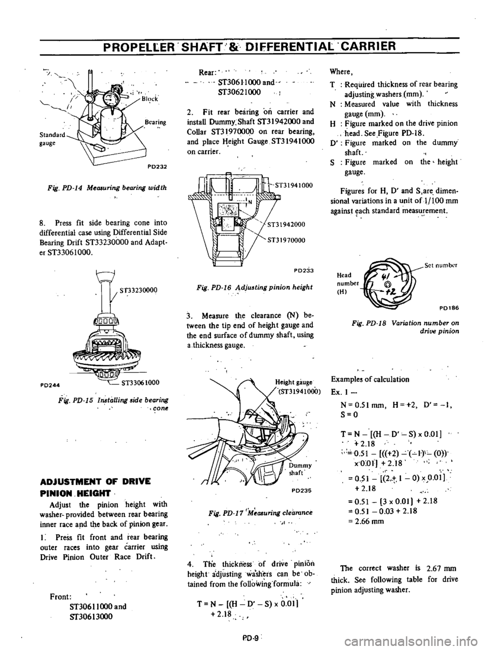
Fig
PD
14
Me
uring
bearing
width
8
Press
fit
side
bearing
cone
into
differential
case
using
Differential
Side
Bearing
Drift
ST33230000
and
Adapt
er
ST33061000
t
J
I
ST33230000
io
o1
P0244
Fig
PD
15
ln
talling
side
bearing
cone
ADJUSTMENT
OF
DRIVE
PINION
HEIGHT
Adjust
the
pinion
height
with
washer
provided
between
rear
bearing
inner
race
a
ld
the
back
of
pinion
gear
Press
fit
front
and
rear
bearing
outer
races
into
gear
carrier
using
Drive
Pinion
Ou
ter
Race
Drift
Front
ST306
I
1000
and
Sf30613oo0
Rear
ST306
II
000
and
ST3062I
000
2
Fit
rear
bearing
on
carrier
and
install
Dummy
Shaft
Sf3
I
942000
and
Collar
ST3197oo00
on
rear
bearing
and
place
H
eight
Gauge
ST31941000
on
carrier
ST31941000
PD2
b
Fig
PD
16
Adjusting
pinion
height
3
Measure
the
clearance
N
be
tween
the
tip
end
of
height
gauge
and
the
end
surface
of
dummy
shaft
using
a
thickness
gauge
P0235
Fig
PD
17
Measuring
clearance
4
Tlie
thickness
of
drive
pInIOn
height
adjusting
wa
sh
ers
can
be
ob
tained
from
the
following
formula
T
N
H
0
S
x
0
01
2
18
PD
9
Where
T
Required
thickness
of
rear
bearing
adjusting
washers
mOl
N
Measured
value
with
thickness
gauge
mOl
H
Figure
marked
on
the
drive
pinion
head
See
Figure
PD
18
0
Figure
marked
on
the
dummy
shaft
S
Figure
marked
on
the
height
gauge
Figures
for
H
0
and
S
are
dimen
sional
variations
in
a
unit
of
1
100
mOl
against
each
standard
measurement
Head
number
HI
P0186
Set
numbl
r
Fig
PD
18
Variation
number
on
drive
pinion
Examples
of
calculation
Ex
I
N
0
5Imm
H
2
0
1
S
O
T
N
H
D
S
xO
01
2
18
0
51
2
I
0
x
O
ol
2
18
O
SI
2
t
1
0
x
0
01
2
18
0
51
3
x
0
01
2
18
0
51
0
03
2
18
2
66
mOl
The
correct
washer
is
2
67
mm
thick
See
following
table
for
drive
pinion
adjusting
washer
Page 358 of 537
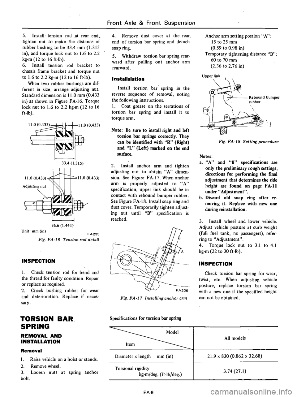
s
Install
tension
rod
at
rear
end
tighten
nut
to
make
the
distance
of
rubber
bushing
to
be
33
4
mm
1
315
in
and
torque
lock
nut
to
1
6
to
2
2
kg
m
12
to
16
ft
lb
6
Install
tension
rod
bracket
to
chassis
frame
bracket
and
torque
nut
to
1
6
to
2
2
kg
m
12
to
16
ft
lb
When
two
rubber
bushings
are
dif
ferent
in
size
arrange
adjusting
nut
Standard
dimension
is
11
0
mOl
0
433
in
as
shown
in
Figure
FA
16
Torque
lock
nut
to
1
6
to
2
2
kg
m
12
to
16
ft
lb
Il
0
11
0
0
433
t
lP
33
4
1
315
I
11
0
0
433
1
0
11
0
0
433
Adjusting
nut
Y
i
w
36
6
l
441
Unit
mm
in
FA235
Fig
FA
16
Tension
rod
detail
INSPECTION
I
Check
tension
rod
for
bend
and
the
thread
for
faulty
condition
Repair
or
replace
as
required
2
Check
bushing
rubber
for
wear
and
deterioration
Replace
if
neces
sary
TORSION
BAR
SPRING
REMOVAL
AND
INSTALLATION
Removal
1
Raise
vehicle
on
a
hoist
or
stands
2
Remove
wheel
3
Loosen
nuts
at
spring
anchor
bolt
Front
Axle
Front
Suspension
4
Remove
dust
cover
at
the
rear
end
of
torsion
bar
spring
and
detach
snap
ring
S
Withdraw
torsion
bar
spring
rear
ward
after
pulling
ou
t
anchor
arm
realWard
I
nstallalation
Install
torsion
bar
spring
in
the
reverse
sequence
of
removal
noting
the
following
instructions
I
Coat
grease
on
the
serrations
of
torsion
bar
spring
and
install
it
to
torque
arm
Note
Be
sure
to
install
right
and
left
torsion
bar
springs
correctly
They
can
be
identified
with
R
Right
and
L
Left
marked
on
the
end
surface
2
Install
anchor
arm
and
tighten
adjusting
nut
to
obtain
A
dimen
sion
See
Figure
F
A
17
When
anchor
arm
is
properly
adjusted
to
A
specification
upper
link
should
be
in
contact
with
rebound
bumper
rubber
See
Figure
FA
18
Install
snap
ring
and
dust
cover
Temporarily
tighten
adjust
ing
nut
until
B
specification
is
reached
I
I
I
FA236
Fig
FA
17
Installing
anchor
arm
Specifications
for
torsion
bar
spring
Diameter
x
length
mOl
in
Torsional
rigidity
kg
m
deg
ft
lb
deg
FA
9
Anchor
arm
setting
post
ion
A
ISt02Smm
0
59
to
0
98
in
Temporary
tightening
distance
B
60
to
70
mOl
2
36
to
2
76
in
UjPPje
Rebound
bumper
rubber
j
4W
Fig
FA
18
Setting
procedure
Notes
3
A
and
8
specifications
are
only
the
preliminary
rough
settings
directions
for
performing
the
final
adjustment
that
determines
the
ride
height
are
found
on
page
F
A
II
under
Adjustment
b
Discard
old
snap
ring
after
re
moving
it
Replace
with
new
one
during
reinstallation
3
Install
wheel
and
lower
vehicle
Adjust
vehicle
posture
at
curb
weight
full
fuel
tank
no
passengers
refer
ring
to
Adjustment
4
Torque
lock
nut
to
3
1
to
4
1
kg
m
22
to
30
ft
lb
INSPECTION
Check
torsion
bar
spring
for
wear
twist
etc
When
adjusting
vehicle
posture
replace
torsion
bar
spring
with
a
new
one
if
the
specified
height
can
not
be
obtained
All
models
21
9
x
830
0
862
x
32
68
3
74
27
I
Page 363 of 537
Front
Axle
Front
Suspension
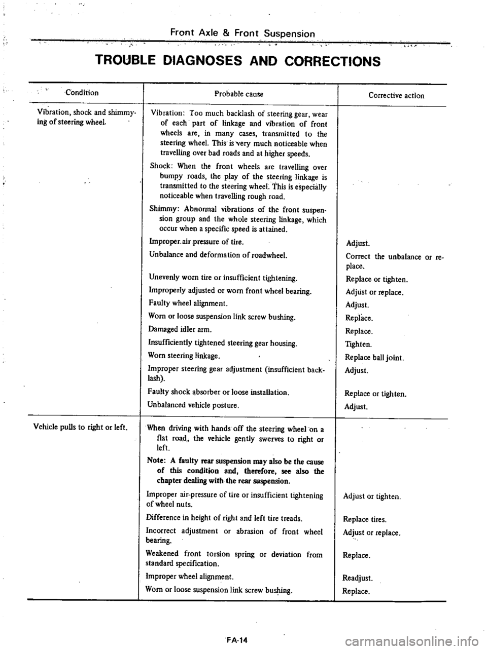
TROUBLE
DIAGNOSES
AND
CORRECTIONS
Condition
Vibration
shock
and
shimmy
ing
of
steering
wheeL
Vehicle
pulls
to
right
or
left
Probable
cause
Vibration
Too
much
backlash
of
steering
gear
wear
of
each
part
of
linkage
and
vibration
of
front
wheels
are
in
many
cases
transmitted
to
the
steering
wheel
This
is
Very
much
noticeable
when
traveJling
over
bad
roads
and
at
higher
speeds
Shock
When
the
front
wheels
are
travelling
over
bumpy
roads
the
play
of
the
steering
linkage
is
transmitted
to
the
steering
wheel
This
is
especially
noticeable
when
travelling
rough
road
Shimmy
Abnormal
vibrations
of
the
front
suspen
sion
group
and
the
whole
steering
linkage
which
occur
when
a
specific
speed
is
attained
Improper
air
pressure
of
tire
Unbalance
and
deformation
of
roadwheel
Unevenly
worn
tire
or
insufficient
tightening
Improperly
adjusted
or
worn
front
wheel
bearing
Faulty
wheel
alignment
Worn
or
loose
suspension
link
screw
bushing
Damaged
idler
arm
Insufficiently
tightened
steering
gear
housing
Worn
steering
linkage
Improper
steering
gear
adjustment
insufficient
back
lash
Faulty
shock
absorber
or
loose
installation
Unbalanced
vehicle
posture
When
driving
with
hands
off
the
steering
wheel
on
a
fiat
road
the
vehicle
gently
swerves
to
right
or
left
Note
A
faulty
rear
suspension
may
also
be
the
cause
of
this
condition
and
therefore
see
also
the
chapter
dealing
with
the
rear
suspension
Improper
air
pressure
of
tire
or
insufficient
tightening
of
wheel
nu
ts
Difference
in
height
of
right
and
left
tire
treads
Incorrect
adjustment
or
abrasion
of
front
wheel
bearing
Weakened
front
torsion
spring
or
deviation
from
standard
specification
Improper
wheel
alignment
Worn
or
loose
suspension
link
screw
bushing
FA
14
Corrective
action
Adjust
Correct
the
unbalance
or
re
place
Replace
or
tighten
Adjust
or
replace
Adjust
Replace
Replace
TIghten
Replace
ball
joint
Adjust
Replace
or
tighten
Adjust
Adjust
or
tighten
Replace
tires
Adjust
or
replace
Replace
Readjust
Replace
Page 377 of 537
The
620
series
vehicles
are
equip
ped
with
hydraulic
brakes
on
the
four
wheels
and
mechanical
hand
brakes
on
the
rear
wheels
The
front
brake
is
the
uni
servo
type
and
the
rear
the
duo
servo
with
the
built
in
hand
BRAKE
PEDAL
FRONT
BRAKE
REAR
BRAKE
BRAKE
PEDAL
Qi
f
l
II
t
Unit
mm
in
I
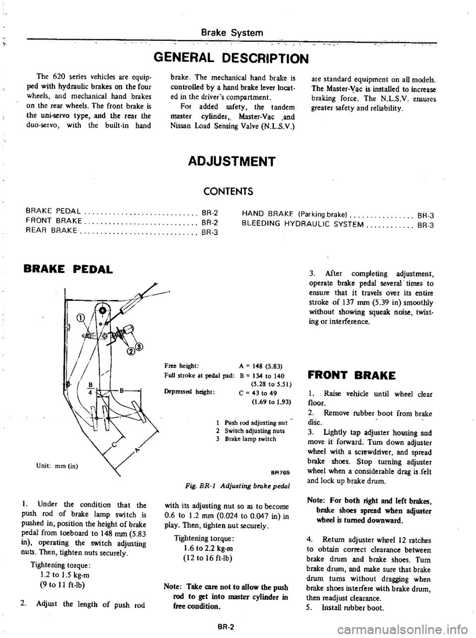
Under
the
condition
that
the
push
rod
of
brake
lamp
swi
tch
is
pushed
in
position
the
height
of
brake
pedal
from
toeboard
to
148
mm
5
83
in
operating
the
switch
adjusting
nuts
Then
tighten
nuts
securely
Tightening
torque
1
2
to
1
5
kg
m
9
to
I
I
ft
Ib
2
Adjust
the
length
of
push
rod
Brake
System
GENERAL
DESCRIPTION
brake
The
mechanical
hand
brake
is
controlled
by
a
hand
brake
lever
locat
ed
in
the
driver
s
compartment
For
added
safety
the
tandem
I
1lI3ter
cylinder
Master
Vac
and
Nissan
Load
Sensing
Valve
N
L
S
V
ADJUSTMENT
CONTENTS
are
standard
equipment
on
all
models
The
Master
Vac
is
installed
to
increase
braking
force
The
N
L
S
V
ensures
greater
safety
and
reliability
BR
2
BR
2
BR
3
HAND
BRAKE
Parking
brake
BLEEDING
HYDRAULIC
SYSTEM
BR
3
BR
3
Free
height
Full
stroke
at
pedal
pad
A
148
5
83
B
134
10
140
5
28
to
5
51
C
43
to
49
1
69
to
1
93
Depressed
height
1
Push
rod
adjusting
nut
2
Switch
adjusting
nuts
3
BraKe
lamp
switch
BA765
Fig
BR
l
Adjusting
brake
pedal
with
its
adjusting
nut
so
as
to
become
0
6
to
1
2
mOl
0
024
to
0
047
in
in
play
Then
tigh1en
nut
securely
Tightening
torque
1
6
to
2
2
kg
m
12
to
16
ft
lb
Note
Take
care
not
to
allow
the
push
rod
to
get
into
master
cylinder
in
free
condition
BR
2
3
After
completing
adjustment
operate
brake
pedal
several
times
to
ensure
that
it
travels
over
its
entire
stroke
of
137
mm
5
39
in
smoothly
without
showing
squeak
noise
twist
ing
or
interference
FRONT
BRAKE
1
Raise
vehicle
until
wheel
clear
floor
2
Remove
rubber
boot
from
brake
disc
3
Ughtly
tap
adjuster
housing
and
move
it
forward
Turn
down
adjuster
wheel
with
a
screwdriver
and
spread
brake
shoes
Stop
turning
adjuster
wheel
when
a
considerable
drag
is
Jelt
and
lock
up
brake
drum
Note
For
both
right
and
left
brakes
brake
shoes
spread
when
adjuster
wheel
is
turned
downward
4
Return
adjuster
wheel
12
ratches
to
obtain
correct
clearance
between
brake
drum
and
brake
shoes
Turn
brake
drum
and
make
sure
that
brake
drum
turns
without
dragging
when
brake
shoes
interfere
with
brake
drum
then
readjust
clearance
5
Install
rubber
boot
Page 395 of 537
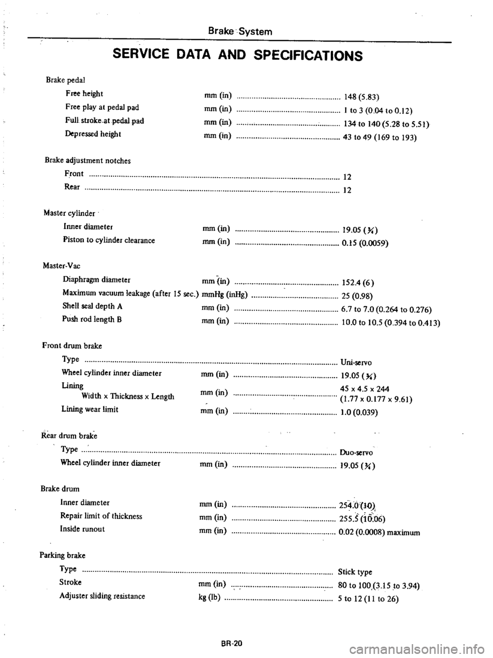
Brake
System
SERVICE
DATA
AND
SPECIFICATIONS
Brake
pedal
Free
height
Free
play
at
pedal
pad
Full
stroke
at
pedal
pad
Depressed
height
mOl
in
mOl
in
mOl
in
mm
in
148
S
83
I
to
3
0
04
to
0
12
134
to
140
5
28
to
S
51
43
to
49
169
to
193
Brake
adjustment
notches
Front
Rear
12
12
Master
cylinder
Inner
diameter
Piston
to
cylinder
deaJance
mm
in
mm
in
19
0S
Yo
O
IS
0
OOS9
Master
Vac
Diaphragm
diameter
mOl
in
Maximum
vacuum
leakage
after
15
sec
mmHg
inHg
Shell
seal
depth
A
mOl
in
Push
rod
length
B
mOl
in
152
4
6
2S
0
98
6
7
to
7
0
0
264
to
0
276
10
0
to
10
5
0
394
to
0
413
Front
drum
brake
Type
Wheel
cylinder
inner
diameter
Lining
Width
x
Thickness
x
Length
Lining
wear
limit
Uni
servo
mm
in
I9
0S
Yo
45
x
4
5
x
244
1
77
x
0
177
x
9
61
1
0
0
039
mm
in
mOl
in
Rear
drum
brake
Type
Wheel
cylinder
inner
diameter
Duo
servo
mOl
in
19
0S
Yo
Brake
drum
Inner
diameter
Repair
limit
of
thickness
Inside
runout
mm
in
mOl
in
mOl
in
254
0
10
2SS
S
10
06
0
02
0
0008
maximum
PaJking
brake
Type
Stroke
Adjuster
sliding
resistance
mm
in
kg
lb
Stick
type
80
to
100
3
lS
to
3
94
S
to
12
11
to
26
BR
20
Page 397 of 537
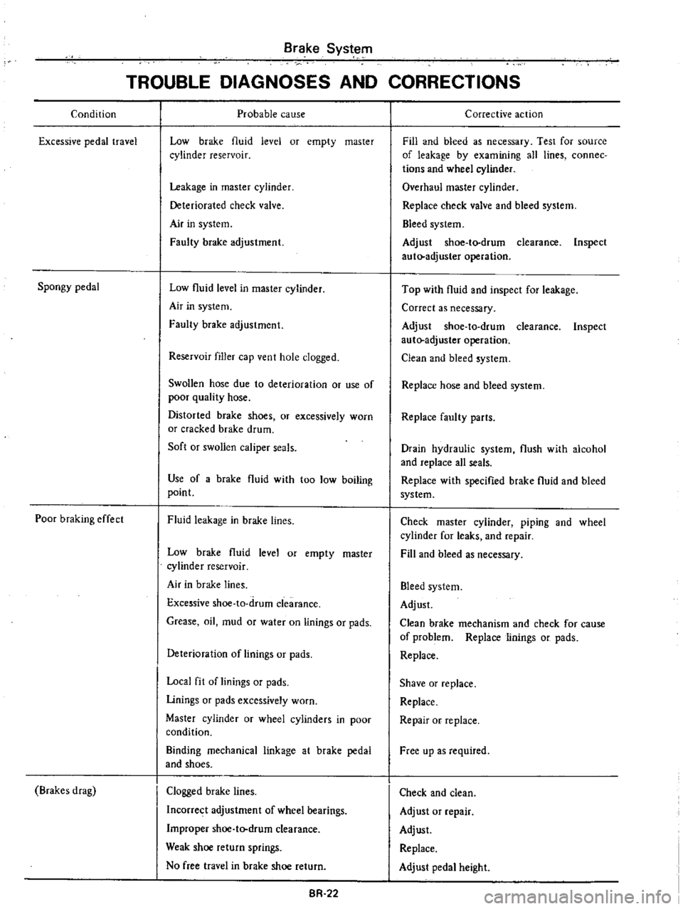
Condition
Excessive
pedal
travel
Spongy
pedal
Poor
braking
effect
Brakes
drag
Brake
Syst
em
TROUBLE
DIAGNOSES
AND
CORRECTIONS
Probable
cause
Low
brake
1uid
level
or
empty
master
cylinder
reservoir
Leakage
in
master
cylinder
Deteriorated
check
valve
Air
in
system
Faulty
brake
adjustment
Low
1uid
level
in
master
cylinder
Air
in
system
Faulty
brake
adjustment
Reservoir
filler
cap
vent
hole
clogged
Swollen
hose
due
to
deterioration
or
use
of
poor
quality
hose
Distorted
brake
shoes
or
excessively
worn
or
cracked
brake
drum
Soft
or
swollen
caliper
seals
Use
of
a
brake
1uid
with
too
low
boiling
point
Fluid
leakage
in
brake
lines
Low
brake
1uid
level
or
empty
master
cylinder
reservoir
Air
in
brake
lines
Excessive
shoe
ta
drum
clearance
Grease
oil
mud
or
water
on
linings
or
pads
Deterioration
of
linings
or
pads
Local
fit
of
linings
or
pads
Linings
or
pads
excessively
worn
Master
cylinder
or
wheel
cylinders
in
poor
condition
Binding
mechanical
linkage
at
brake
pedal
and
shoes
Clogged
brake
lines
Incorrect
adjustment
of
wheel
bearings
Improper
shoe
t
drum
clearance
Weak
shoe
return
springs
No
free
travel
in
brake
shoe
return
BR
22
Corrective
action
Fill
and
bleed
as
necessary
Test
for
source
of
leakage
by
examining
all
lines
connec
tions
and
wheel
cylinder
Overhaul
master
cylinder
Replace
check
valve
and
bleed
system
Bleed
system
Adjust
shoe
to
drum
clearance
Inspect
auto
adjuster
operation
Top
with
1uid
and
inspect
for
leakage
Correct
as
necessary
Adjust
shoe
to
drum
clearance
Inspect
aut
adjuster
operation
Clean
and
bleed
system
Replace
hose
and
bleed
system
Replace
faulty
parts
Drain
hydraulic
system
flush
with
alcohol
and
replace
all
seals
Replace
with
specified
brake
1uid
and
bleed
system
Check
master
cylinder
pIpIng
and
wheel
cylinder
for
leaks
and
repair
Fill
and
bleed
as
necessary
Bleed
system
Adjust
Clean
brake
mechanism
and
check
for
cause
of
problem
Replace
linings
or
pads
Replace
Shave
or
replace
Replace
Repair
or
replace
Free
up
as
required
Check
and
clean
Adjust
or
repair
Adjust
Replace
Adjust
pedal
height
Page 418 of 537
Engine
Control
Fuel
Exhaust
Systems
REMOVAL
AND
INSTALLATION
Accelerator
wire
I
Remove
air
cleaner
assembly
2
Disconnect
accelerator
wire
from
carburetor
3
Loosen
lock
nut
and
disconnect
accelerator
wire
outer
case
from
wire
holder
See
Figure
FE
I
4
Remove
spring
clamp
and
discon
nect
accelerator
wire
from
accelerator
pedal
arm
S
Remove
two
screws
securing
ac
celerator
wire
outer
case
to
body
and
detach
accelerator
wire
6
To
install
reverse
the
order
of
removal
Apply
recommended
multi
purpose
grease
slightly
to
portion
MG
shown
in
Figure
FE
I
Accelerator
pedal
assembly
I
Remove
spring
clamp
then
dis
connect
accelerator
wire
from
tip
of
pedal
ann
2
Remove
two
screws
securing
ac
celerator
pedal
bracket
to
body
3
Remove
accelerator
pedal
from
dash
panel
See
Figure
FE
I
4
To
install
reverse
the
order
of
removal
INSPECTION
I
Check
accelerator
pedal
return
spring
for
rust
fatigue
or
damage
Replace
if
necessary
2
Check
accelerator
wire
cases
and
fastening
locations
for
rust
damage
or
looseness
Repair
or
replace
if
necessary
ADJUSTMENT
Accelerstor
pedal
and
wire
Adjust
pedal
stopper
bolt
Section
A
so
as
to
obtain
specifi
ed
height
E
as
shown
in
Figure
FE
I
Secure
pedal
stopper
bolt
with
stopper
lock
nut
Refer
to
Figure
FE
I
E
78
mOl
3
07
in
Tightening
torque
01
nut
0
38
to
0
4S
kg
m
2
7
to
3
2
ft
b
2
Release
auto
choke
effect
since
throttle
lever
is
opened
by
fast
idle
earn
until
engine
warms
up
I
Keep
choke
valve
fully
open
with
fingers
2
Pull
throttle
lever
up
by
hand
1
Adjust
nut
2
Lock
nut
3
Accelerator
wire
4
Dust
co
r
5
After
completing
the
adjustment
as
previously
explained
check
the
following
I
Make
sure
that
accelerator
system
functions
smoothly
and
quietly
without
disturbing
any
adjacent
parts
2
Depress
accelerator
pedal
down
until
throttle
valve
fully
opens
Make
sure
that
the
clearance
T
between
accelerator
pedal
reverse
side
and
dash
floor
is
2
to
4
mm
0
08
to
0
16
in
without
floor
mat
Adjust
pedal
stop
per
bolt
and
lock
nut
if
beyond
limits
3
Check
throttle
lever
if
it
returns
to
the
original
position
as
soon
as
accelerator
pedal
is
released
FE
3
then
automatic
choke
effect
will
be
released
3
Set
throttle
valve
to
completely
closed
position
and
with
wire
suf
ficiently
slackened
lighten
adjust
nut
until
throttle
lever
is
about
to
move
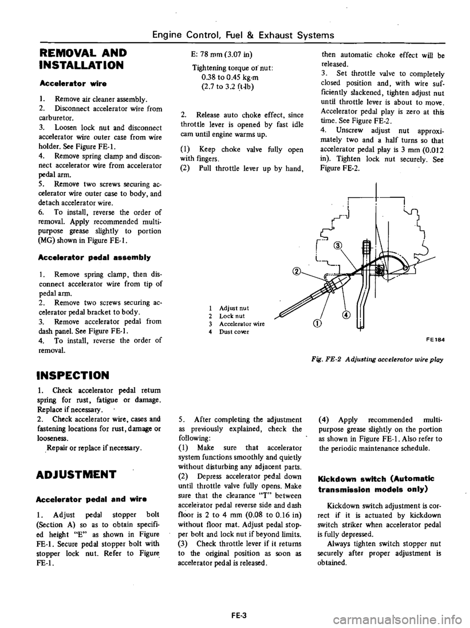
Accelerator
pedal
play
is
zero
at
this
lime
See
Figure
FE
2
4
Unscrew
adjust
nut
approxi
mately
two
and
a
half
turns
so
that
accelerator
pedal
play
is
3
mOl
0
012
in
Tighten
lock
nut
securely
See
Figure
FE
2
1
I
1
CD
@
FE184
Fig
FE72
AdjU6ting
accelerator
wire
play
4
Apply
recommended
multi
purpose
grease
slightly
on
the
portion
as
shown
in
Figure
FE
I
Also
refer
to
the
periodic
maintenance
schedule
Kickdown
switch
Automatic
transmission
models
only
Kickdown
switch
adjustment
is
cor
rect
if
it
is
actuated
by
kickdown
switch
striker
when
accelerator
pedal
is
fully
depressed
Always
tighten
switch
stopper
nut
securely
after
proper
adjustment
is
obtained