horn DATSUN PICK-UP 1977 Service Manual
[x] Cancel search | Manufacturer: DATSUN, Model Year: 1977, Model line: PICK-UP, Model: DATSUN PICK-UP 1977Pages: 537, PDF Size: 35.48 MB
Page 49 of 537

r
I
I
PRELIMINARY
CLEANING
AND
INSPECTION
DISASSEMBL
Y
PRELIMINARY
CLEANING
AND
INSt
ECTION
Before
disassembling
engine
note
the
following
I
Fuel
oil
or
water
may
leak
past
cylinder
head
and
block
Prior
to
disassembling
check
cylinder
head
1
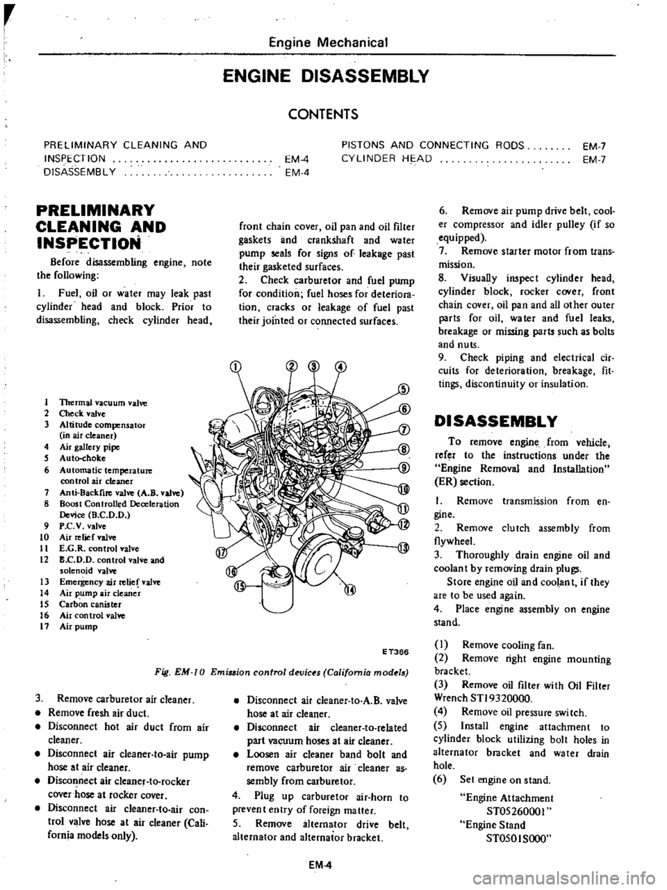
1ltermal
vacuum
valve
2
Check
valve
3
Altitude
compensator
in
air
cleaner
4
Air
gallery
pipe
S
Auto
choke
6
Automatic
temperature
control
air
cleaner
7
Anti
8ackfire
valve
A
B
valve
8
Boost
Controlled
Deceleration
Device
Bee
D
D
9
P
c
v
valve
to
Air
relief
valve
11
E
G
R
control
valve
12
B
C
D
D
control
valve
and
solenoid
valve
13
Emergency
air
relief
valve
14
Air
pump
air
cleaner
IS
Carbon
canister
16
Air
control
valve
11
Air
pump
Engine
Mechanical
ENGINE
DISASSEMBLY
CONTENTS
EM
4
EM
4
PISTONS
AND
CONNECTING
RODS
CYLINDER
HE
AD
EM
7
EM
7
front
chain
cover
oil
pan
and
oil
filter
gaskets
lInd
crankshaft
and
water
pump
seals
for
signs
of
leakage
past
their
gasketed
surfaces
2
Check
carburetor
and
fuel
pump
for
condition
fuel
hoses
for
deteriora
tion
cracks
or
leakage
of
fuel
past
their
jointed
or
connected
surfaces
Fig
EM
0
Emiuion
control
devic
s
California
mod
18
E
T366
3
Remove
carburetor
air
cleaner
Remove
fresh
air
duct
Disconnect
hot
air
duct
from
air
cleaner
Disconnect
air
cleaner
to
air
pump
hose
at
air
cleaner
Disconnect
air
cleanef
to
rocker
cover
hose
at
rocker
cover
Disconnect
air
cIeaner
to
air
con
trol
valve
hose
at
air
cleaner
Cali
fornia
models
only
Disconnect
air
cleaner
to
A
B
valve
hose
at
air
cleaner
Disconnect
air
cleaner
to
related
part
vacuum
hoses
at
air
cleaner
Loosen
air
cleaner
band
bolt
and
remove
carburetor
air
cleaner
as
sembly
from
carburetor
4
Plug
up
carburetor
air
horn
to
prevent
entry
of
foreign
matter
5
Remove
alternator
drive
belt
alternator
and
alternator
bracket
EM
4
6
Remove
air
pump
drive
belt
cool
er
compressor
and
idler
pulley
if
so
equipped
7
Remove
starter
motor
from
trans
mission
8
Visually
inspect
cylinder
head
cylinder
block
rocker
C
Ner
front
chain
cover
oil
pan
and
all
other
outer
parts
for
oil
water
and
fuel
leaks
breakage
or
missing
parts
such
as
bolts
and
nuts
9
Check
piping
and
electrical
cir
cuits
for
deterioration
breakage
fit
tings
discontinuity
or
insulation
DISASSEMBLY
To
remove
engine
from
vehicle
refer
to
the
instructions
under
the
Engine
Removal
and
Installation
ER
section
I
Remove
transmission
from
en
gine
2
Remove
clutch
assembly
from
flywheeL
3
Thoroughly
drain
engine
oil
and
coolan
t
by
removing
drain
plugs
Store
engine
oil
and
coolant
if
they
are
to
be
used
again
4
Place
engine
assembly
on
engine
stand
I
Remove
cooling
fan
2
Remove
right
engine
mounting
bracket
3
Remove
oil
filter
with
Oil
Filter
Wrench
STI9320000
4
Remove
oil
pressure
swi
tch
5
Install
engine
attachment
to
cylinder
block
utilizing
bolt
holes
in
alternator
bracket
and
water
drain
hole
6
Set
engine
on
stand
Engine
Attachment
ST05260001
Engine
Stand
ST050I
SOOO
Page 141 of 537

Emission
Control
System
C
bur
tor
I
EC284
When
installing
this
valve
ensure
that
it
properly
oriented
Tlus
valve
shuuld
be
replaced
periodically
Refer
to
Maintenance
Schedule
Note
Carburetor
side
Black
DisInDutor
side
Brown
horn
distributor
To
carburetor
TOdi
ribUI0
carburClor
EC
lCiJr
Fig
EC
9
Operation
01
park
delay
value
INSPECTION
Remove
spark
delay
valve
2
Blow
air
through
port
on
carbure
tor
side
then
through
the
other
port
on
distributor
side
Spark
delay
valve
Distributor
side
1
One
way
umbrella
valve
2
Sintered
metal
disc
Fig
EC
8
Spark
delay
valve
is
in
good
condition
if
when
finger
is
placed
over
port
on
distributor
side
air
flow
resistance
is
greater
than
that
on
the
other
side
See
Figur
ET
lO
3
If
a
considerable
air
flow
resist
ance
is
fell
at
port
on
distributor
side
in
step
2
above
and
if
the
condition
of
spark
delay
valve
is
questionable
dip
port
on
carburetor
side
into
a
cup
filled
with
water
Blow
air
through
the
other
port
Small
air
bubbles
should
appear
Carburetor
side
Distributor
side
EC346
Fig
EC
IO
Checking
park
delay
valve
EC
8
EC219
Fig
EC
11
Checking
spark
d
tay
valve
Note
Be
careful
to
avoid
entry
of
oil
or
dirt
into
valve
AIR
INJECTION
SYSTEM
DESCRIPTION
The
Air
Injection
System
A
LS
is
aeSigiieino
iiiject
coin
pressed
air
sec
ODllary
air
corning
from
the
air
pump
into
the
exhaust
manifold
to
reduce
hydrocarbons
and
carbon
monoxide
in
exhaust
lri
s
through
re
combustion
There
are
two
types
of
A
I
S
One
type
is
mounted
on
California
models
and
the
other
is
on
non
California
models
The
non
California
type
con
sists
of
an
air
pump
air
cleaner
an
air
pump
a
relief
valve
a
check
valve
an
anti
backfIre
valve
an
air
gallery
and
hoses
The
California
type
has
in
addition
to
the
components
of
the
non
California
type
an
air
control
valve
and
an
emergency
air
relief
valve
These
valves
prevent
ahnonnal
tem
perature
rise
of
the
catalytic
converter
Page 151 of 537

Air
pump
I
Operate
engine
until
it
reaches
normal
operating
temperature
2
Inspect
all
hose
hose
connec
tions
and
air
gallery
for
leaks
and
correct
if
necessary
before
checking
air
injection
pump
3
Check
air
injection
pump
belt
tension
and
adjust
to
specifications
if
necessary
4
Disconnect
air
supply
hose
at
check
valve
5
Disconnect
vacuum
hose
from
the
air
control
valve
California
type
only
6
Insert
open
pipe
end
of
Air
Pump
Test
Gauge
Adapter
STl9870000
in
air
supply
hose
Clamp
hose
securely
to
adapter
to
prevent
it
from
blowing
out
Position
adapter
and
test
lli
uge
so
that
air
blast
emitted
through
drilled
pipe
plug
will
be
harmlessly
dissipated
7
Install
a
tachometer
on
engine
With
engine
speed
at
2
600
rpm
ob
serve
pressure
produced
at
test
gauge
Air
pressure
should
be
100
mmHg
3
94
inHg
or
more
8
If
air
pressure
does
not
meet
above
specifications
proceed
as
fol
lows
I
Repeat
2
and
3
above
2
Disconnect
air
supply
hose
at
anti
backfire
valve
Plug
air
hose
open
ing
and
screw
with
a
clamp
Repeat
pressure
test
3
With
engine
speed
at
1
500
rpm
close
hole
of
test
gauge
with
finger
If
a
leaking
sound
is
heard
or
leaking
air
is
felt
by
ftnger
at
relief
valve
relief
valve
is
malfunctioning
Relief
valve
should
be
replaced
or
repaired
4
If
air
injection
pump
does
not
meet
minimum
requirement
of
pres
sure
test
it
should
be
replaced
Control
valve
The
following
procedures
are
reo
commended
for
checking
and
or
as
certaining
that
the
various
components
of
the
exhaust
emission
con
Irol
system
are
operating
properly
The
engine
and
all
components
must
be
at
normal
operating
tempera
tures
when
the
tests
are
performed
Prior
to
performing
any
extensive
diag
nosis
of
the
exhaust
control
system
it
Emission
Control
System
must
be
determined
that
the
engine
as
a
unit
is
functioning
properly
Check
valva
Warm
up
engine
thoroughly
2
Disconnect
hose
leading
to
check
valve
from
air
hose
COJUlector
3
Check
hose
opening
for
any
indi
cation
of
exhaust
gas
leaks
Ifleaks
are
detected
replace
check
valve
4
Race
the
engine
lightly
at
about
2
000
cpm
and
then
return
it
to
idling
VisuaDy
check
the
hose
for
any
indication
of
exhaust
gas
leaks
before
the
engine
returns
to
idling
speed
If
leaks
are
detected
replace
check
valve
EC310
Fig
EC
43
Checking
check
valve
Air
pump
raIle
valve
After
completing
inspection
of
air
pump
check
air
pump
relief
valve
in
the
following
steps
J
Disconnect
hoses
leading
to
check
valve
and
air
control
valve
from
air
hose
connector
and
install
blind
cap
to
the
connector
2
With
engine
running
at
about
3
000
rpm
under
no
load
place
your
hand
on
the
air
outlet
of
air
pump
relief
valve
to
check
for
discharged
air
If
no
air
is
felt
replace
the
air
pump
relief
valve
EC311
Fig
EC
44
Checking
air
pump
relief
valve
EC
18
Air
control
valve
C
U
ornla
models
I
Warm
up
engine
thoroughly
2
Before
checking
air
control
valve
check
all
hoses
for
loose
connection
leaks
etc
and
repair
or
correct
if
necessary
3
With
engine
idling
disconnect
the
outlet
side
hose
of
the
air
control
valve
and
place
your
hand
on
the
air
hose
outlet
to
check
for
air
If
no
air
is
felt
replace
the
air
control
valve
4
Pull
vacuum
hose
off
from
air
con
trol
valve
If
discharge
of
air
from
air
hose
stops
the
air
con
trol
valve
is
normaL
If
discharge
is
still
felt
replace
the
valve
Plug
up
the
removed
vacuum
hose
to
stabilize
engine
running
EC312
Fig
EC
45
Checking
air
control
valve
Emarsancy
air
rella
valve
E
A
R
Valve
lCalHornla
models
L
Warm
up
engine
thoroughly
2
Before
checking
air
control
valve
check
all
hoses
for
loose
connection
leaks
etc
and
repair
or
correct
if
necessary
3
Race
engine
approximately
2
000
rpm
under
no
load
Place
your
hand
on
air
outlet
of
E
A
R
valve
to
check
for
presence
of
discharged
air
If
no
air
is
felt
E
A
R
valve
is
normal
4
Disconnect
vacuum
hose
from
B
A
R
valve
as
shown
in
Figure
EC
46
Page 408 of 537

STEERING
GEAR
Removal
and
installation
Removal
I
Disconnect
battery
ground
cable
from
the
terminal
2
Remove
horn
pad
by
unscrewing
two
bolts
from
the
rear
side
of
steering
wheel
bar
Note
Be
sure
to
punch
mark
with
0
on
the
top
of
steering
column
shaft
Fig
ST
3
R
moving
horn
pad
STEERING
SYSTEM
A
@
@l
@
J
i
u
p
I
1
jj
ST199
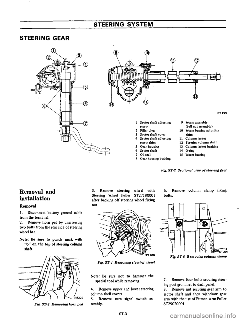
Sector
shaft
adjusting
screw
2
Filler
plug
3
Sector
shaft
cover
4
Sector
shaft
adjusting
screw
shim
5
Gear
housing
6
Sector
shaft
7
Oil
l
8
Gear
housing
bushing
3
Remove
steering
wheel
with
Steering
Wheel
Puller
ST27I80001
after
backing
off
steering
wheel
fIXing
nut
Fig
ST
4
Removing
teering
wheel
Note
Be
sure
not
to
hammer
the
special
tool
while
removing
4
Remove
upper
and
lower
steering
column
shell
covers
S
Remove
turn
signal
switch
as
sembly
ST3
9
Worm
assembly
ball
nut
assembly
10
Worm
bearing
adjusting
shim
11
Column
jacket
12
Steering
column
shaft
13
Column
jacket
bushing
14
ring
15
Worm
bearing
Fig
ST
2
Sectional
view
of
steering
gear
6
Remove
column
clamp
fixing
bolts
c
@
I
f
c
I
1
I
1
i
T201
Fig
ST
5
Removing
column
clamp
7
Remove
four
bolts
securing
steer
ing
post
grommet
to
dash
panel
8
Remove
nut
securing
gear
arm
to
sector
shaft
and
then
withdraw
gear
arm
with
the
use
of
Pitman
Arm
Puller
ST2902000I
Page 466 of 537

Body
Electrical
System
ELECTRICAL
ACCESSORIES
CONTENTS
HORN
DESCRIPTION
REMOVAL
AND
INSTALLATION
IGNITION
SWITCH
REMOVAL
AND
INSTALLATION
INSPECTION
WINDSHIELD
WIPER
AND
WASHER
REMOVAL
AND
INSTALLATION
INSPECTION
RADIO
REMOVAL
AND
INSTALLATION
ADJUSTMENT
CLOCK
REMOVAL
I
NST
ALLA
TION
HEATER
DESCRIPTION
AIRFLOW
HEATER
UNIT
ASSEMBLY
BE
21
BE
21
BE
21
8E
n
BE
22
BE
22
BE
23
BE
23
BE
23
BE
25
BE
25
BE
25
BE
25
BE
25
BE
26
BE
26
BE
26
BE
28
BE
29
HORN
DESCRIPTION
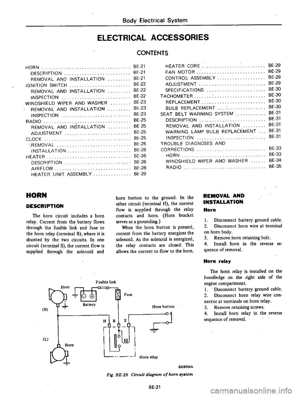
The
horn
circuit
includes
a
horn
relay
Current
from
the
battery
flows
through
the
fusible
link
and
fuse
to
the
horn
relay
terminal
B
where
it
is
shunted
by
the
two
circuits
In
one
circuit
terminal
S
the
current
flow
is
supplied
through
the
solenoid
and
Fusible
link
Qi
att
Fu
H
I
HIBQ
t
J
JJI
L
J
Hornrelay
Qm
HEATER
CORE
FAN
MOTOR
CONTROL
ASSEMBLY
ADJUSTMENT
SPECIFICATIONS
TACHOMETER
REPLACEMENT
8UL8
REPLACEMENT
SEAT
8ELT
WARNING
SYSTEM
DESCRIPTION
REMOVAL
AND
INSTALLATION
WARNING
LAMP
BULB
REPLACEMENT
INSPECTION
TROUBLE
DIAGNOSES
AND
CORRECTIONS
HORN
WINDSHIELD
WIPER
AND
WASHER
RADIO
Horn
button
BE859A
Fig
BE
29
Circuit
diagram
of
horn
sy
tem
horn
button
to
the
ground
In
the
other
circuit
terminal
H
the
current
flow
is
supplied
through
the
relay
contacts
and
horn
Horn
bracket
serves
as
a
grounding
When
the
horn
button
is
pressed
current
from
the
battery
energizes
the
solenoid
As
the
solenoid
is
energized
the
relay
contacts
are
closed
This
allows
the
current
to
flow
to
the
horn
BE
21
REMOVAL
AND
INSTALLATION
Horn
8E
29
BE
29
BE
29
8E
29
BE
30
BE
30
BE
30
8E
30
8E
31
BE
31
BE
31
8E
31
8E
31
BE
33
8E
33
8E
34
BE
35
I
Disconnect
battery
ground
cable
2
Disconnect
horn
wire
at
terminal
on
horn
body
3
Remove
horn
retaining
bolt
4
Install
horn
in
the
reverse
se
quence
of
removal
Horn
relay
The
horn
relay
is
installed
on
the
hoodIedge
on
the
right
side
of
the
engine
compartment
I
Disconnect
battery
ground
cable
2
Disconnect
horn
relay
wire
con
nector
at
terminals
on
horn
relay
3
Remove
retaining
screws
4
Install
horn
relay
in
the
reverse
sequence
of
removal
Page 467 of 537

Body
Electrical
System
Horn
switch
The
horn
switch
is
integral
with
the
turn
signal
and
dimmer
switch
as
sembly
Remove
switch
assembly
as
outlined
in
Turn
Signal
and
Dimmer
Switch
IGNITION
SWITCH
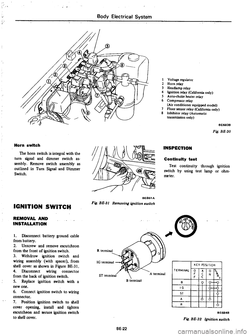
BE861A
Fig
BE
3
I
Removing
ignition
switch
REMOVAL
AND
INSTALLATION
I
Disconnect
battery
ground
cable
from
battery
2
Unscrew
and
remove
escutcheon
from
the
front
of
ignition
switch
3
Withdraw
ignition
switch
and
wiring
assembly
with
spacer
from
shell
cover
as
shown
in
Figure
BE
3
4
Disconnect
wiring
connector
from
the
back
of
ignition
switch
5
Replace
ignition
switch
with
a
new
one
6
Connect
ignition
switch
to
wiring
connector
7
Position
ignition
switch
to
shell
cover
opening
install
and
tighten
escutcheon
and
secure
ignition
switch
to
shell
cover
R
terminal
1G
terminal
ST
terminal
B
terminal
8E
22
1
Voltage
regulator
2
Horn
relay
3
Headlamp
relay
4
Ignition
relay
California
only
5
Auto
choke
heater
relay
6
Compressor
relay
Au
conditioner
equipped
model
7
Floor
sensor
relay
California
only
8
Inhibitor
relay
Automatic
tran5mission
only
INSPECTION
BE683B
Fig
BE
30
ContInuity
test
Test
continuity
through
ignition
switch
by
using
test
lamp
or
ohm
meter
C
A
terminal
TERMINAL
0
F
F
B
IG
ST
A
R
KEY
FOSITlON
t
1
o
j
u
u
I
I
A
C
C
Fig
BE
32
Ignition
witch
BE6848
Page 478 of 537

Body
Electrical
System
TROUBLE
DIAGNOSES
AND
CORRECTIONS
HORN
Condition
Horn
does
not
operate
Horn
sounds
continuously
Reduced
volume
and
or
tone
quality
Probable
cause
Discharged
battery
Measure
specific
gravity
of
electrolyte
Burnt
fuse
Faulty
horn
button
contact
Horn
sounds
when
horn
relay
terminal
s
is
grounded
Inoperative
horn
relay
Horn
sounds
when
B
and
H
horn
relay
tenninals
are
connected
with
a
test
lead
Damaged
horn
or
loose
horn
terminal
con
nection
Short
circuited
horn
button
and
or
horn
button
lead
wire
When
light
green
lead
wire
is
disconnected
from
horn
relay
terminal
s
horn
stops
to
sound
Inoperative
horn
relay
Loose
or
poor
connector
contact
Fuse
relay
horn
and
or
horn
button
Damaged
horn
BE
33
Corrective
action
Recharge
or
replace
battery
Correct
cause
and
replace
fuse
Repair
horn
button
Replace
horn
relay
Correct
horn
te
inal
onnection
or
replace
horn
Repair
horn
button
or
its
wiring
Replace
horn
relay
Repair
Replace
Page 481 of 537

CD
m
Cl
@
D
@
I
j
1
To
instrument
harness
IS
To
battery
30
To
check
connector
2
To
full
transistor
amplifier
16
To
fusible
link
3t
To
headlamp
L
U
type
2
California
models
only
17
To
engine
harness
No
2
32
To
sido
marker
lamp
L
B
3
To
hood
switch
18
To
alternator
33
To
front
combination
lamp
L
H
4
To
engine
compartment
lamp
1
9
To
front
combination
lamp
R
n
34
To
horn
Low
ll
l
S
To
washer
motor
20
To
headlamp
R
H
type
2
3S
To
horn
High
l
l
0
6
To
auto
choke
heater
relay
1
To
side
marker
lamp
R
n
36
To
B
C
D
D
cut
olenoid
California
models
7
To
detector
dri
e
counter
22
To
headlamp
R
B
type
1
only
Non
Califunia
model
except
for
Canada
23
To
ground
37
To
block
tcrminal
distributor
California
8
To
ignition
relay
California
models
only
i4
To
thermal
transmitter
models
only
9
To
floor
sensor
relay
California
modeb
only
is
To
distributor
Non
California
models
only
38
To
ignition
coil
Non
California
models
only
n
10
To
inhibitor
relay
A
T
only
26
To
8
C
D
D
cut
solenoid
Non
California
39
To
condenser
t
II
To
head
lamp
relay
models
only
40
To
ignition
coil
and
resistor
@
12
To
horn
relay
27
To
fuel
cut
solenoid
California
models
only
OJ
v
m
13
To
voltage
regulator
28
To
auto
choke
heater
g
e
14
To
cooler
cable
29
To
headlamp
L
R
type
1
OJ
to
o
Q
m
r0
C
1
i
Ql
CIl
Il
l
3