width DATSUN PICK-UP 1977 Service Manual
[x] Cancel search | Manufacturer: DATSUN, Model Year: 1977, Model line: PICK-UP, Model: DATSUN PICK-UP 1977Pages: 537, PDF Size: 35.48 MB
Page 62 of 537
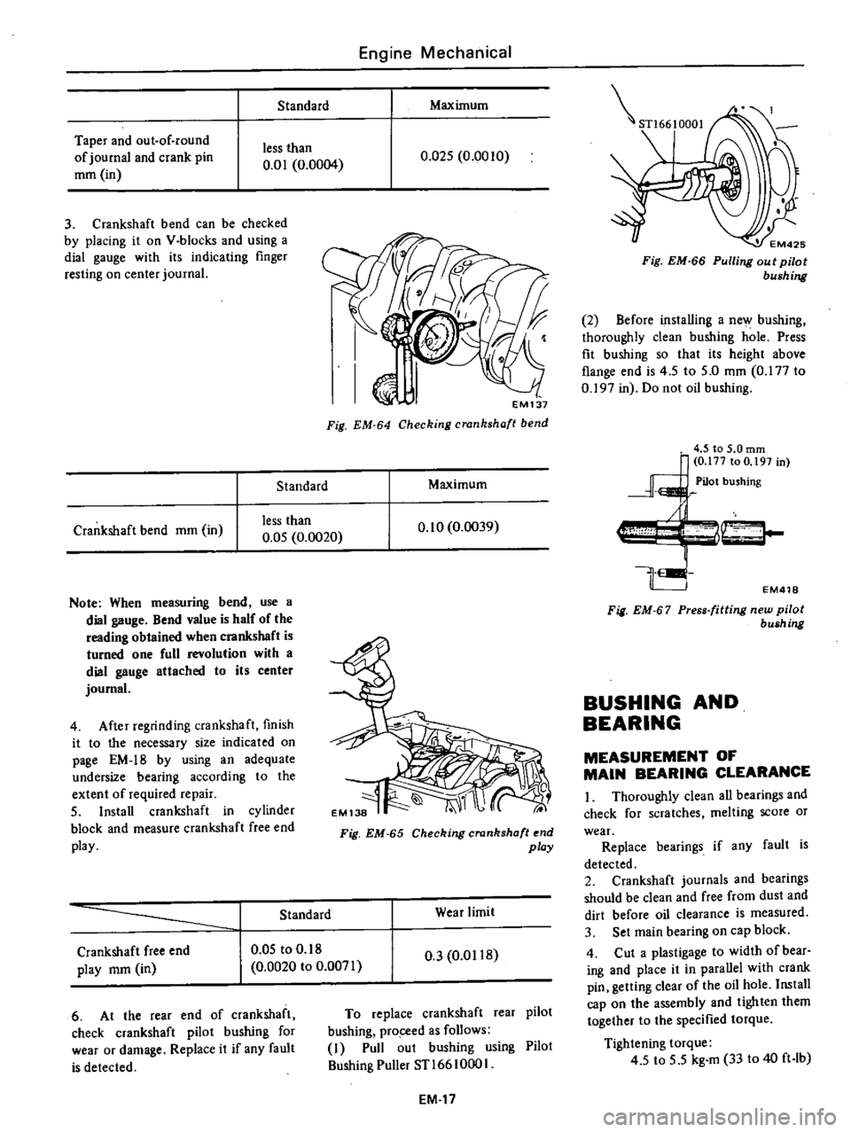
Standard
Taper
and
out
of
round
of
journal
and
crank
pin
mm
in
less
than
0
01
0
0004
3
Crankshaft
bend
can
be
checked
by
placing
it
on
V
blocks
and
using
a
dial
gauge
with
its
indicating
finger
resting
on
center
journal
Standard
Crankshaft
bend
mm
in
less
than
0
05
0
0020
Note
When
measuring
bend
use
a
dial
gauge
Bend
value
is
half
of
the
reading
obtained
when
crankshaft
is
turned
one
full
revolution
with
a
dial
gauge
attached
to
its
center
journal
4
After
regrinding
crankshaft
finish
it
to
the
necessary
size
indicated
on
page
EM
18
by
using
an
adequate
undersize
bearing
according
to
the
extent
of
required
repair
5
Install
crankshaft
in
cylinder
block
and
measure
crankshaft
free
end
play
Engine
Mechanical
Maximum
0
Q25
0
0010
EM137
Fig
EM
64
Checking
crankshaft
bend
Maximum
0
10
0
0039
Fig
EM
65
Checking
crankshaft
end
play
Standard
Wear
limit
Crankshaft
free
end
play
mm
in
0
05
to
0
18
0
0020
to
0
0071
0
3
0
0118
6
At
the
rear
end
of
crankshaft
check
crankshaft
pilot
bushing
for
wear
or
damage
Replace
it
if
any
fault
is
detected
To
replace
crankshaft
rear
pilot
bushing
pro
ceed
as
follows
I
Pull
out
bushing
using
Pilot
Bushing
Puller
STl66
1000
I
EM
17
STl6610001
EM425
Fig
EM
66
Pulling
out
pilot
bushing
2
Before
installing
a
new
bushing
thoroughly
clean
bushing
hole
Press
fit
bushing
so
that
its
height
above
flange
end
is
4
5
to
5
0
mm
0
177
to
0
197
in
Do
not
oil
bushing
EM418
Fig
EM
67
Press
fitting
new
pilot
bush
ng
BUSHING
AND
BEARING
MEASUREMENT
OF
MAIN
BEARING
CLEARANCE
I
Thoroughly
clean
all
bearings
and
check
for
scratches
melting
score
or
wear
Replace
bearings
if
any
fault
is
detected
2
Crankshaft
journals
and
bearings
should
be
clean
and
free
from
dust
and
dirt
before
oil
clearance
is
measured
3
Set
main
bearing
on
cap
block
4
Cut
a
plastigage
to
width
of
bear
ing
and
place
it
in
parallel
with
crank
pin
getting
clear
of
the
oil
hole
Install
cap
on
the
assembly
and
tighten
them
together
to
the
specified
torque
Tightening
torque
4
5
to
5
5
kg
m
33
to
40
ft
lb
Page 63 of 537
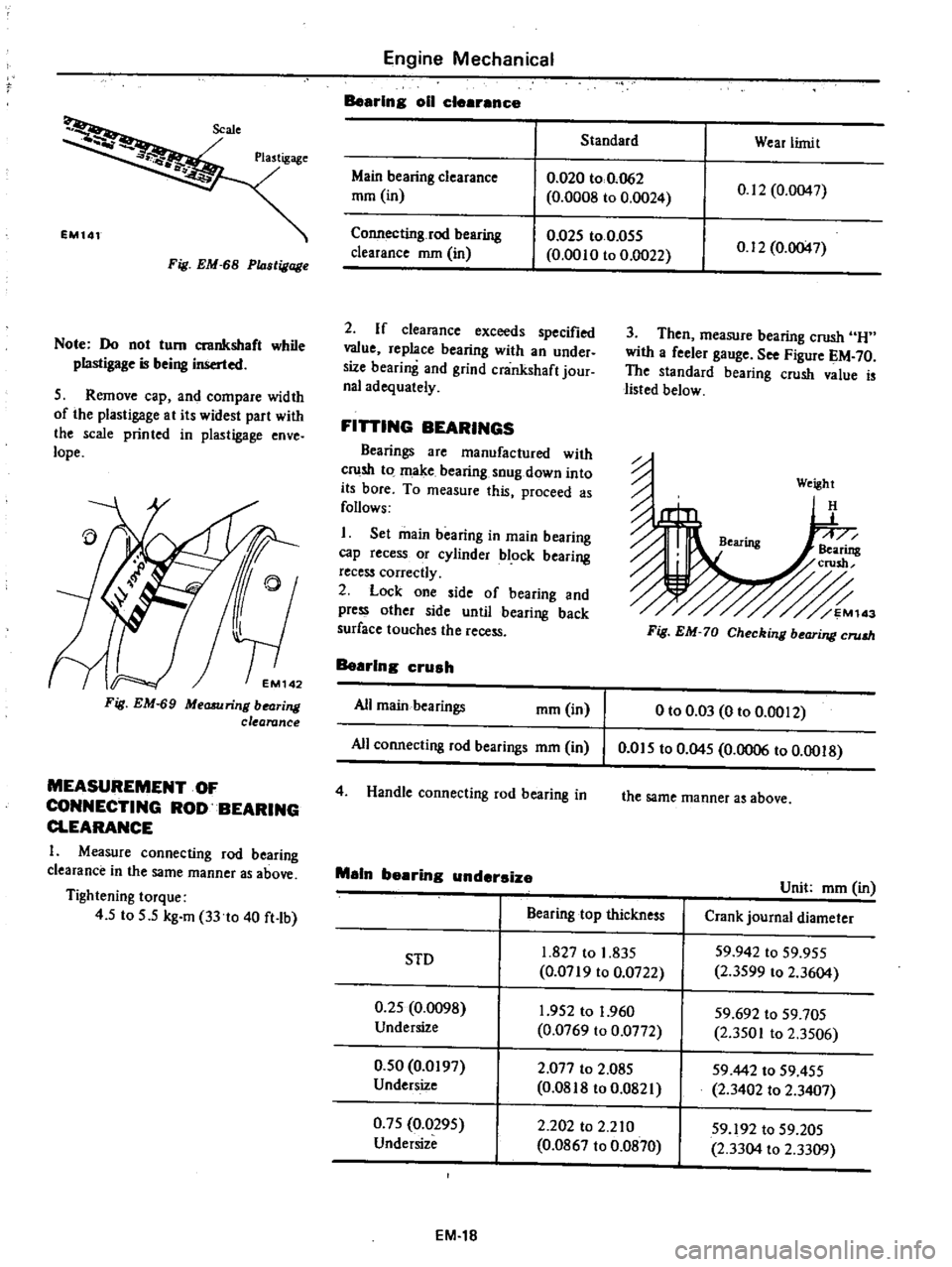
Fig
EM
68
P14stigage
Note
Do
not
tum
crankshaft
while
plastigage
is
being
inserted
5
Remove
cap
and
compare
width
of
the
plastigage
at
its
widest
part
with
the
scale
printed
in
plastigage
enve
lope
Fig
EM
69
Measuring
bearing
clearance
MEASUREMENT
OF
CONNECTING
ROD
BEARING
CLEARANCE
I
Measure
connecting
rod
bearing
clearance
in
the
same
manner
as
above
Tightening
torque
4
5
to
5
5
kg
m
33
to
40
ft
lb
Engine
Mechanical
Bearing
011
clearance
Standard
Wear
limit
Main
bearing
clearance
mm
in
0
020
to
0
062
0
0008
to
0
0024
0
12
0
0047
Connecting
rod
bearing
clearance
mm
in
0
025
to
0
055
0
0010
to
0
0022
0
12
0
0047
2
If
clearance
exceeds
specified
value
replace
bearing
with
an
under
size
bearing
and
grind
crankshaft
jour
nal
adequately
FiniNG
BEARINGS
Bearings
are
manufactured
with
crush
to
make
bearing
snug
down
into
its
bore
To
measure
this
proceed
as
follows
I
Set
main
bearing
in
main
bearing
cap
recess
or
cylinder
block
bearing
recess
correctly
2
Lock
one
side
of
bearing
and
press
other
side
until
bearing
back
surface
touches
the
recess
Bearing
crush
All
main
bearings
mm
in
All
connecting
rod
bearings
mm
in
4
Handle
connecting
rod
bearing
in
3
Then
measure
bearing
crush
H
with
a
feeler
gauge
See
Figure
EM
70
The
standard
bearing
crush
value
is
listed
below
Weight
H
Fig
EM
70
Checking
bearing
crum
o
to
0
03
0
to
0
0012
0
015
to
0
045
0
0006
to
0
0018
the
same
manner
as
above
Main
bearing
undersize
Unit
mm
in
Bearing
top
thickness
Crank
journal
diameter
1
827
to
1
835
59
942
to
59
955
SID
0
0719
to
0
0722
2
3599
to
2
3604
0
25
0
0098
1
952
to
1
960
59
692
to
59
705
Undersize
0
0769
to
0
0772
2
3501
to
2
3506
0
50
0
0197
2
077
to
2
085
59442
to
59
455
Undersize
0
0818
to
0
0821
2
3402
to
2
3407
0
75
0
0295
2
202
to
2
210
59
192
to
59
205
Undersize
0
0867
to
0
0870
2
3304
to
2
3309
EM
18
Page 73 of 537
Valve
spring
pressured
length
valve
open
Intake
and
exhaust
Outer
Inner
Valve
spring
assembled
height
valve
close
Intake
and
exhaust
Outer
Inner
Valve
guide
length
Intake
and
exhaust
Valve
guide
height
from
head
surface
Valve
guide
inner
diameter
Intake
and
exhaust
Valve
guide
outer
diameter
service
parts
Intake
and
exhaust
Valve
guide
to
stem
clearance
Intake
Exhaust
Valve
seat
width
Intake
Exhaust
Valve
seat
angle
Intake
and
exhaust
Valve
seat
interference
fit
Intake
Exhaust
Valve
guide
interference
fit
b
Camshaft
and
timing
chain
Camshaft
end
play
Camshaft
lobe
ift
Intake
and
exhaust
Camshaft
joumal
diameter
1st
2nd
3rd
and
4th
Engine
Mechanical
mm
kg
in
lb
mm
kg
in
lb
mm
in
mIll
in
mm
in
mm
in
mm
in
mm
in
mm
in
mm
in
rnm
in
rnm
in
mm
in
Camshaft
bend
mm
in
Camshaft
journal
to
bearing
clearance
mm
in
Camshaft
bearing
inner
diameter
rnm
in
1st
2nd
3rd
and
4th
29
5
49
0
1
IM
108
24
5
25
5
0
965
56
2
40
0
21
3
1
575
47
0
35
0
12
3
1
378
27
I
59
0
2
323
10
6
0
417
8
000
to
8
018
0
3150
to
0
3157
12
223
to
12
234
0
4812
to
0
4817
0
020
to
0
053
0
0008
to
0
0021
0
040
to
0
073
0
0016
to
0
0029
1
4
to
1
6
0
0551
to
0
0630
1
8
to
2
2
0
0709
to
0
0866
450
0
081
to
0
113
0
0032
to
0
0044
0
064
to
0
096
0
0025
to
0
0038
0
027
to
0
049
0
0011
to
0
0019
0
08
to
038
0
0032
to
0
0150
7
0
0
276
47
949
to
47
962
1
8877
to
1
8883
0
02
0
0008
0
Q38
to
0
067
0
00
I
5
to
0
0026
48
000
to
48
016
1
8898
to
1
8904
EM
28
Page 74 of 537
Engine
Mechanical
c
Connecting
rod
Center
distance
mm
in
Bearing
thickness
Standard
mm
in
Big
end
play
mm
in
Connecting
rod
bearing
clearance
mm
in
Connecting
rod
bend
or
torsion
per
100
mm
or
2
937
in
mm
in
d
Crankshaft
and
main
bearing
Journal
diameter
Journal
taper
out
of
round
Crankshaft
free
end
play
Wear
limit
of
dittoed
play
Crank
pin
diameter
Crank
pin
taper
out
of
round
Main
bearing
thickness
StJlndard
146
5
748
1
493
to
1
506
0
0588
to
0
0593
0
20
to
0
30
0
008
to
0
012
0
D25
to
0
055
0
0010
to
0
0022
less
than
0
03
0
0012
mm
in
mm
in
mm
in
mm
in
mm
in
mm
in
mm
in
59
942
to
59
955
2
3599
io
2
3604
less
than
0
0
I
0
0004
0
05
to
0
18
0
0020
to
0
0071
0
3
0
0118
49
961
to
49
974
1
9670
to
1
9675
less
than
0
01
0
0004
1
827
to
1
835
0
0719
to
0
0722
0
020
to
0
062
0
0008
to
0
0024
0
12
0
0047
0
05
0
0020
Main
bearing
clearance
mm
in
Wear
limit
of
dittoed
clearance
mm
in
Crankshaft
bend
mm
in
Flywheel
runout
at
clutch
disc
contact
face
mm
in
e
Piston
Pistondiarneter
Service
standard
0
50
0
0197
Oversize
1
00
0
0394
Oversize
Ring
groove
width
Top
Second
Oil
Piston
to
bore
clearance
Piston
pin
hole
off
set
Piston
pin
hole
diameter
f
Piston
pin
Pin
diameter
Pin
length
less
than
0
15
0
0059
mm
in
84
985
to
85
035
3
3459
to
3
3478
85
465
to
85
515
3
3648
to
3
3667
85
965
to
86
015
3
3844
to
3
3864
2
030
to
2
050
0
0799
to
0
0807
2
020
to
2
040
0
0795
to
0
0803
4
015
to
4
040
0
1581
to
0
1591
0
Q25
to
0
045
0
0010
to
0
0018
0
95
to
1
05
0
0374
to
0
0413
21
001
to
21
008
0
8268
to
0
8271
mm
in
mm
in
mm
in
mm
in
mm
in
mm
in
mm
in
20
993
to
20
998
0
8265
to
0
8267
72
25
to
73
00
2
8445
to
2
8740
0
008
to
om
0
0
0003
to
0
0004
mm
in
Piston
pin
to
piston
clearance
mm
in
Interference
fit
of
piston
pin
to
connecting
rod
bushing
mm
in
om
5
to
0
035
0
0006
to
0
00
I
4
EM
29
Page 327 of 537
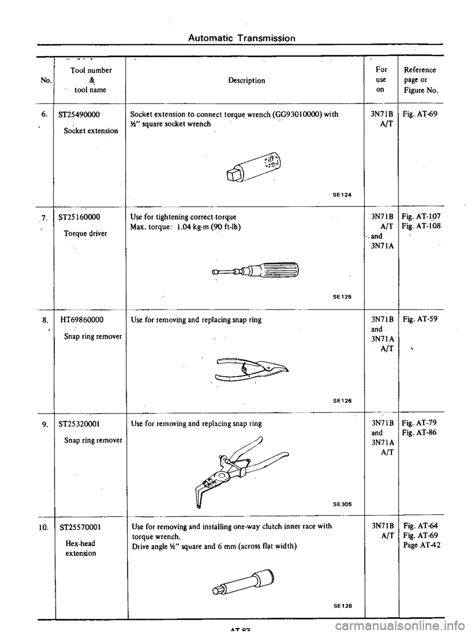
Automatic
Transmission
Tool
number
For
Reference
No
Description
use
page
or
tool
name
on
Figure
No
6
ST2S490000
Socket
extension
to
connect
torque
wrench
GG93010000
with
3N71B
Fig
AT
69
Socket
extension
W
square
socket
wrench
AIT
V
SE124
7
ST2S160000
Use
for
tightening
correct
torque
3N71B
Fig
AT
107
Torque
driver
Max
torque
1
04
kg
m
90
ft
lb
A
T
Fig
AT
108
and
3N71A
3
SE125
8
HT69860000
Use
for
removing
and
replacing
snap
ring
3N71B
Fig
AT
S9
and
Snap
ring
remover
3N71A
AIT
SE126
9
ST2S320001
Use
for
removing
and
replacing
snap
ring
3N71B
Fig
AT
79
and
Fig
AT
86
Snap
ring
remover
3N71A
AIT
SE305
Hex
head
extension
Use
for
removing
and
installing
one
way
clutch
inner
race
with
torque
wrench
Drive
angle
W
square
and
6
mOl
across
flat
width
3N71B
AIT
Fig
AT
64
Fig
AT
69
Page
AT
42
10
ST2SS70001
SE128
AT
I
Page 336 of 537
PROPElli
ER
SHAfT
DIFFERENTIAL
G
ARRIERf
Notes
a
PUller
should
be
handled
with
care
in
catchins
the
edge
of
bearing
inner
race
b
Be
careful
not
to
confuse
left
and
right
hand
parts
2
Remove
ring
gear
by
spreading
out
lock
strap
and
loosening
ring
gear
bolts
in
diagonally
3
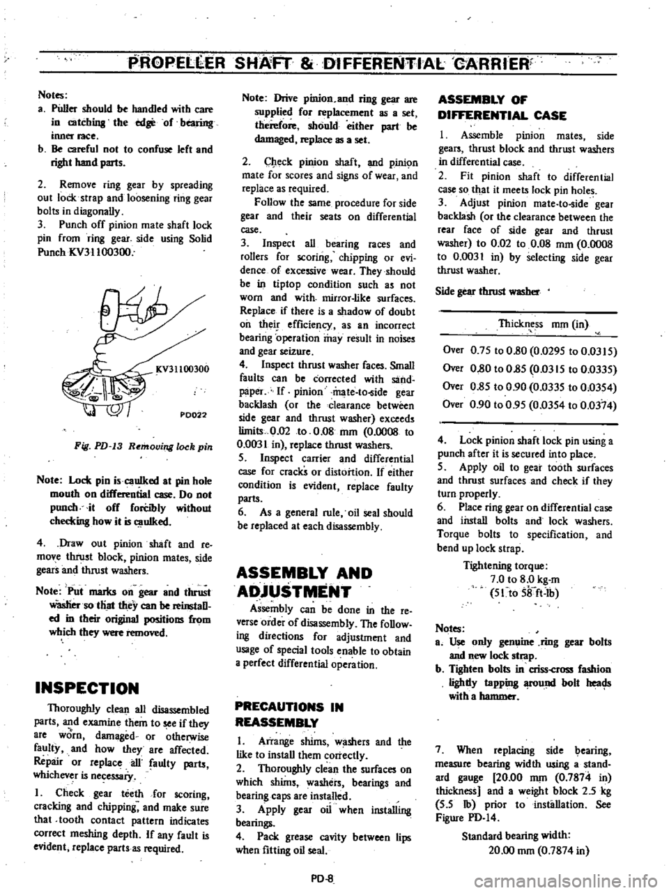
Punch
off
pinion
mate
shaft
lock
pin
from
ring
gear
side
using
Solid
Punch
ICV31100300
KV31100300
PD022
Fig
PD
13
Removing
lock
pin
Note
Lock
pin
i
cauIked
at
pin
hole
mouth
on
differential
case
Do
not
punch
it
off
forCibly
without
checkins
how
it
is
uIked
4
Draw
out
pinion
shaft
and
re
move
thrust
block
pinion
mates
side
gears
and
thrust
washers
Note
Put
marks
on
gear
and
thrust
Wasliersotliat
they
can
be
reinstaD
ed
in
their
original
positions
from
which
they
were
removed
INSPECTION
Thoroughly
clean
all
disassembled
parts
and
examine
them
to
see
if
they
8re
worn
damaged
or
otherwise
faulty
and
how
they
are
affected
Repair
or
replace
ail
faulty
parts
whichever
is
necessaiy
I
Check
gear
teeth
for
scoring
cracking
and
chipping
and
make
sure
that
tooth
contact
pattern
indicates
correct
meshing
depth
If
any
fault
is
evident
replace
parts
as
required
Note
Drive
pinion
and
ring
gear
are
supplied
for
replacement
as
a
set
therefore
should
either
part
be
damaged
replace
as
a
set
2
Check
pinion
shaft
and
pinic
m
mate
for
scores
and
signs
of
wear
and
replace
as
required
Follow
the
same
procedure
for
side
gear
and
their
seats
on
differential
case
3
Inspect
all
bearing
races
and
rollers
for
scoring
chipping
or
evi
dence
of
excessive
wear
They
should
be
in
tiptop
condition
such
as
not
worn
and
with
mirror
like
surfaces
Replace
if
there
is
a
shadow
of
doubt
oil
their
efficiency
as
an
incorrect
bearing
operation
may
result
in
noises
and
gear
seizure
4
Inspect
thrust
washer
faces
Small
faults
can
be
corrected
with
sand
paper
If
pinion
mate
to
ide
gear
backlash
or
the
clearance
between
side
gear
and
thrust
washer
exceeds
limits
0
02
to
0
08
nun
0
0008
to
0
0031
in
replace
thrust
washers
S
Inspect
carrier
and
differential
case
for
cracks
or
distortion
If
either
condition
is
evident
replace
faulty
parts
6
As
a
general
rule
oil
seal
should
be
replaced
at
each
disassembly
ASSEMBLY
AND
ADjUSTMENT
Assembly
can
be
done
in
the
reo
verse
order
of
disassembly
The
foDow
ing
directions
for
adjustment
and
usage
of
special
tools
enable
to
obtain
a
perfect
differential
operation
PRECAUTIONS
IN
REASSEMBLY
I
Arrange
shims
w
shers
and
the
like
to
install
them
correctly
2
Thoroughly
clean
the
surfaces
on
which
shims
washers
bearings
and
bearing
caps
are
installed
3
Apply
gear
oil
when
installing
bearings
4
Pack
grease
cavity
between
lips
when
fitting
oil
seal
PD
8
ASSEMBLY
OF
DIFFERENTIAL
CASE
I
Assemble
pinion
mates
side
gears
thrust
block
and
thrust
washers
in
differential
case
2
Fit
pinion
shaft
to
differential
case
so
that
it
meets
lock
pin
holes
3
Adjust
pinion
mate
to
ide
gear
backlash
or
the
clearance
between
the
rear
face
of
side
gear
and
thrust
washer
to
0
02
to
0
08
mOl
0
0008
to
0
0031
in
by
selecting
side
gear
thrust
washer
Side
gear
thrust
WlISber
Thickness
nun
in
Over
0
7S
to
0
80
0
029S
to
0
03IS
Over
0
80
to
O
8S
Om
IS
to
0
033S
Over
0
8S
to
0
90
0
033S
to
0
03S4
Over
0
90
to
0
9S
0
03S4
to
0
0374
4
Lock
pinion
shaft
lock
pin
using
a
punch
after
it
is
secured
into
place
S
Apply
oil
to
gear
tooth
surfaces
and
thrust
surfaces
and
check
if
they
turn
properly
6
Place
ring
gear
on
differential
case
and
install
bolts
and
lock
washers
Torque
bolts
to
specification
and
bend
up
lock
strap
Tightening
torque
7
0
to
8
0
kg
m
S1to
Sifft
Ib
Notes
ao
Use
only
genuine
ring
gear
bolts
and
new
lock
strap
b
Tighten
bolts
in
criss
cross
fashion
lighdy
tapping
fOund
bolt
heac
Js
with
a
hammer
7
When
replacing
side
bearing
measure
bearing
width
using
a
stand
ard
gauge
20
00
nun
0
7874
in
thickness
and
a
weight
block
2
5
kg
S
S
Ib
prior
to
installation
See
Figure
PD
I4
Standard
bearing
width
20
00
nun
0
7874
in
Page 337 of 537
PROPELLER
SHAFT
DifFERENTIAL
CARRIER
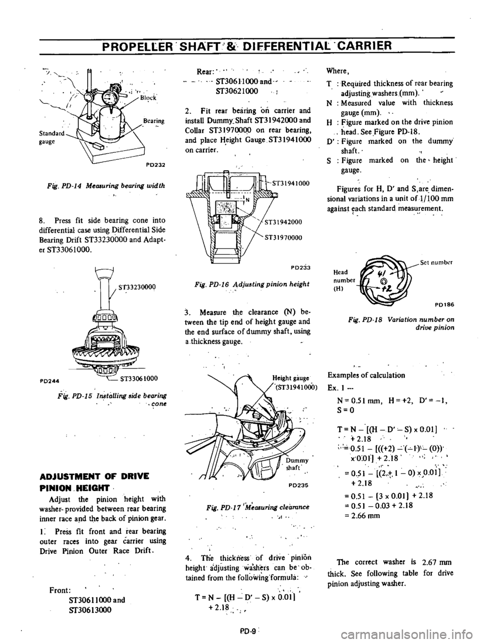
Standard
gauge
I
1
Fig
PD
14
Me
uring
bearing
width
8
Press
fit
side
bearing
cone
into
differential
case
using
Differential
Side
Bearing
Drift
ST33230000
and
Adapt
er
ST33061000
t
J
I
ST33230000
io
o1
P0244
Fig
PD
15
ln
talling
side
bearing
cone
ADJUSTMENT
OF
DRIVE
PINION
HEIGHT
Adjust
the
pinion
height
with
washer
provided
between
rear
bearing
inner
race
a
ld
the
back
of
pinion
gear
Press
fit
front
and
rear
bearing
outer
races
into
gear
carrier
using
Drive
Pinion
Ou
ter
Race
Drift
Front
ST306
I
1000
and
Sf30613oo0
Rear
ST306
II
000
and
ST3062I
000
2
Fit
rear
bearing
on
carrier
and
install
Dummy
Shaft
Sf3
I
942000
and
Collar
ST3197oo00
on
rear
bearing
and
place
H
eight
Gauge
ST31941000
on
carrier
ST31941000
PD2
b
Fig
PD
16
Adjusting
pinion
height
3
Measure
the
clearance
N
be
tween
the
tip
end
of
height
gauge
and
the
end
surface
of
dummy
shaft
using
a
thickness
gauge
P0235
Fig
PD
17
Measuring
clearance
4
Tlie
thickness
of
drive
pInIOn
height
adjusting
wa
sh
ers
can
be
ob
tained
from
the
following
formula
T
N
H
0
S
x
0
01
2
18
PD
9
Where
T
Required
thickness
of
rear
bearing
adjusting
washers
mOl
N
Measured
value
with
thickness
gauge
mOl
H
Figure
marked
on
the
drive
pinion
head
See
Figure
PD
18
0
Figure
marked
on
the
dummy
shaft
S
Figure
marked
on
the
height
gauge
Figures
for
H
0
and
S
are
dimen
sional
variations
in
a
unit
of
1
100
mOl
against
each
standard
measurement
Head
number
HI
P0186
Set
numbl
r
Fig
PD
18
Variation
number
on
drive
pinion
Examples
of
calculation
Ex
I
N
0
5Imm
H
2
0
1
S
O
T
N
H
D
S
xO
01
2
18
0
51
2
I
0
x
O
ol
2
18
O
SI
2
t
1
0
x
0
01
2
18
0
51
3
x
0
01
2
18
0
51
0
03
2
18
2
66
mOl
The
correct
washer
is
2
67
mm
thick
See
following
table
for
drive
pinion
adjusting
washer
Page 339 of 537
PROPELLER
SHAFT
DIFFERENTIAL
CARRIER
Drive
pinion
bearing
adjusting
washer
Thickness
mm
in
over
3
80
to
3
82
0
1496
to
O
lS04
over
3
82
to
3
84
O
lS04
to
0
ISI2
over
3
84
to
3
86
O
lSI2
to
0
IS20
over
3
86
to
3
88
O
lS20
to
O
IS28
over
3
88
to
3
90
O
lS28
to
0
IS3S
over
3
90
to
3
92
0
IS3S
to
O
IS43
over
3
92
to
3
94
0
IS43
to
O
lSS
I
over
3
94
to
3
96
O
lSSI
to
O
lS59
over
3
96
to
3
98
O
lSS9
to
0
IS67
over
3
98
to
4
00
O
lS67
to
O
lS7S
over
4
00
to
4
02
0
S7S
to
O
lS83
over
4
02
to
4
04
O
lS83
to
0
IS91
over
4
04
to
4
06
O
lS9I
to
0
IS98
over
4
06
to
4
08
O
lS98
to
0
1606
over
4
08
to
4
10
0
1606
to
0
1614
3
Check
and
adjust
tooth
contact
pattern
when
former
adjustment
of
bearing
preload
is
completed
Unless
anything
wrong
is
found
remove
drive
pinion
nut
and
companion
flange
and
press
n
oil
seal
into
gear
carrier
using
Oil
Seal
Fitting
Tool
KV38I02SS0
Apply
grease
cavity
be
tween
seal
lips
4
Again
install
companion
flange
and
washer
and
tighteh
nut
to
speci
fied
torque
14
0
to
17
0
kg
m
IO
to
123
ft
lb
S
Measure
preload
again
Preload
with
oil
seal
I
1
0
to
14
0
kg
cm
9
S
to
12
in
lb
At
companion
flange
bolt
hole
3
1
to
4
0
kg
6
8
to
8
81b
ADJUSTMENT
OF
SIDE
BEARING
SHIMS
I
If
hypoid
gear
set
carrier
dif
ferential
case
or
side
bearing
has
been
replaced
with
new
one
adjust
the
side
bearing
preload
with
adjusting
shim
The
required
thickness
of
adjusting
shim
can
be
calculated
by
the
follow
ing
formulas
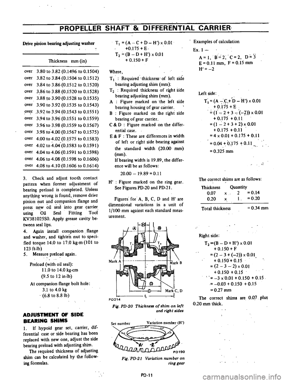
T
A
C
D
H
xO
OI
O
l7S
E
T2
B
D
H
xO
OI
O
ISO
F
Where
T
1
Required
thickness
of
left
side
bearing
adjusting
shim
mm
T
2
Required
thickness
of
right
side
bearing
adjusting
shim
mm
A
Figure
marked
on
the
left
side
bearing
housing
of
gear
carrier
B
Figure
marked
on
the
right
side
bearing
of
gear
carrier
C
0
Figure
marked
on
the
differ
entia
case
E
F
These
are
differences
in
width
of
left
or
right
side
bearing
against
the
standard
width
20
00
mOl
mOl
If
bearing
width
is
19
89
the
differ
ence
will
be
as
follows
20
00
19
89
0
11
H
Figure
marked
on
the
ring
gear
See
Figures
PD
20
and
PD
2
I
Figures
for
A
B
C
0
and
H
are
dimensional
varia
tions
in
a
unit
of
1
100
mm
against
each
standard
meas
urement
f
@
a
rj
71
Markj
Mark
B
Mark
C
0
P0214
Fig
PD
20
Thickn
of
shim
on
l
ft
and
righ
t
sides
Fig
PD
21
Variation
number
on
ring
gear
PD
ll
Examples
of
calculation
Ex
I
A
I
B
2
C
2
0
3
E
0
11
mm
F
O
IS
mm
H
2
Left
side
T
A
C
0
H
x
0
01
O
liS
E
1
2
3
1
x
0
01
0
17S
0
11
1
2
3
2
x
O
O
O
l7S
0
11
4
x
0
01
0
175
0
11
0
04
0
1
7S
0
11
0
32S
mOl
The
correct
shims
are
as
follows
Thickness
0
07
0
20
Quantity
x
2
0
14
x
I
0
20
Total
thickness
0
34
mOl
Right
side
T2
B
0
H
x
0
01
O
lSO
F
2
3
2
x
0
01
O
ISO
0
15
2
3
2
x
0
01
O
ISO
0
15
3
x
O
OI
O
ISO
O
IS
0
03
O
lSO
O
lS
0
27
mm
The
correct
shims
are
0
07
plus
0
20
mm
thick
Page 345 of 537
PROPELlER
SHAFT
DIFfERENTIALCARRI
ER
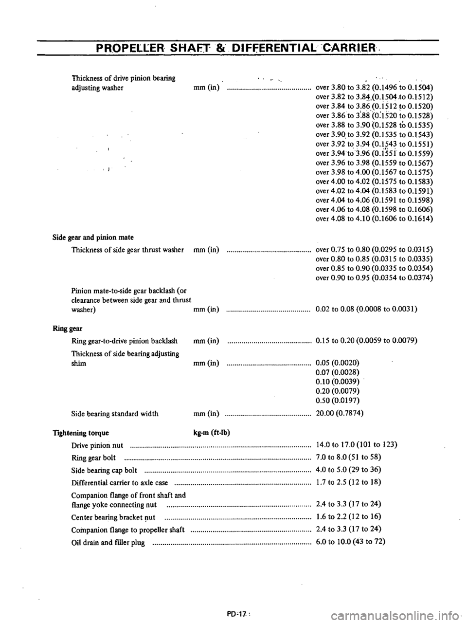
Thickness
of
drive
pinion
bearing
adjusting
washer
mm
in
over
3
80
to
3
82
0
1496
to
O
IS04
over
3
82
to
3
8
HO
IS04
to
OcISI2
over
3
84
to
3
86
0
ISI2
to
0
IS20
over
3
86
to
3
88
0
1520
to
0
IS28
over
3
88
to
3
90
0
IS28
to
0
IS3S
over
3
90
to
3
92
0
IS3S
to
0
1S43
over
3
92
to
3
94
0
1543
to
O
ISSI
over
3
94
to
3
96
0
I5si
to
0
ISS9
over
3
96
to
3
98
0
I5S9
to
0
IS67
over
3
98
to
4
00
0
1567
to
0
IS7S
over
4
00
to
4
02
0
157S
to
0
IS83
over
4
02
to
4
04
0
IS83
to
0
IS91
over
4
04
to
4
06
0
IS91
to
0
IS98
over
4
06
to
4
08
0
1598
to
0
1606
over
4
08
to
4
10
0
1606
to
0
1614
Side
gear
and
pinion
mate
Thickness
of
side
gear
thrust
washer
mOl
in
over
0
7S
to
0
80
0
029S
to
0
03IS
over
0
80
to
0
8S
0
03IS
to
0
033S
over
0
8S
to
0
90
0
0335
to
0
03S4
over
0
90
to
0
9S
0
03S4
to
0
0374
Pinion
mate
to
side
gear
backlash
or
clearance
between
side
gear
and
thrust
washer
mOl
in
0
02
to
0
08
0
0008
to
0
0031
Ring
gear
Ring
gear
to
drive
pinion
backlash
mm
in
Thickness
of
side
bearing
adjusting
shim
mOl
in
O
1S
to
0
20
0
00S9
to
0
0079
Side
bearing
standard
width
mm
in
O
OS
0
0020
0
07
0
0028
0
10
0
0039
0
20
0
0079
0
50
0
0197
20
00
0
7874
TIghtening
torque
Drive
pinion
nut
Ring
gear
bolt
Side
bearing
cap
bolt
Differential
carrier
to
axle
case
Companion
flange
of
front
shaft
and
flange
yoke
connecting
nut
Center
bearing
bracket
ut
Companion
flange
to
propeller
shaft
Oil
drain
and
filler
plug
kg
m
ft
Ib
14
0
to
17
0
101
to
123
7
0
to
8
0
SI
toS8
4
0
to
S
O
29
to
36
17
to
2
S
12
to
18
2
4
to
3
3
17
to
24
1
6
to
2
2
12
to
16
2
4
to
3
3
17
to
24
6
0
to
10
0
43
to
72
PD
l1
Page 373 of 537
Rear
Axle
Rear
Suspension
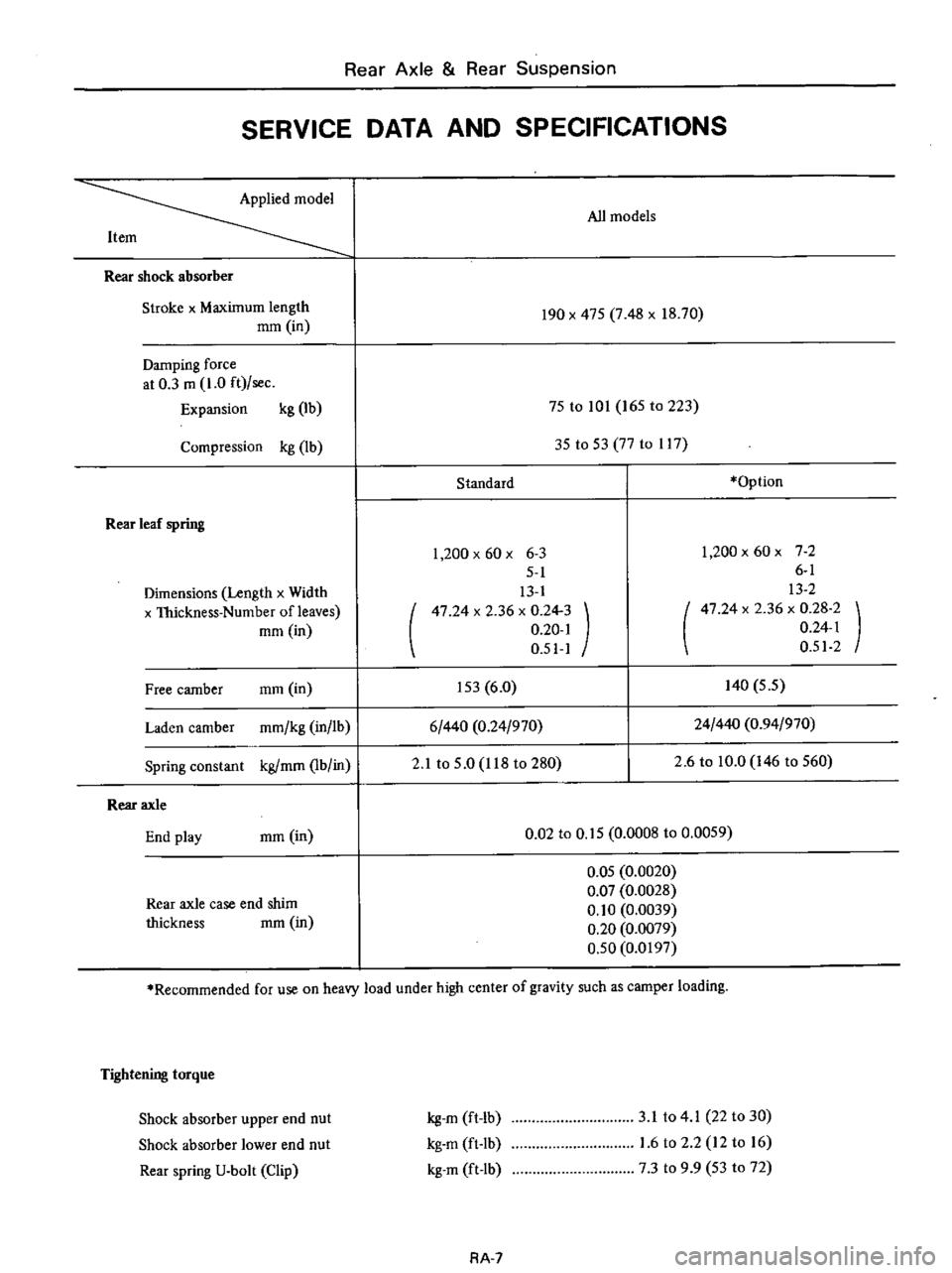
SERVICE
DATA
AND
SPECIFICATIONS
Applied
model
All
models
Item
Rear
shock
absorber
Stroke
x
Maximum
length
mOl
in
190
x
47S
7
48
x
18
70
Damping
force
at
0
3
m
1
0
ft
sec
Expansion
kg
lb
75
to
101
165
to
223
Compression
kg
lb
3S
to
S3
77
to
1l7
Standard
Option
Rear
leaf
spring
Dimensions
Length
x
Width
x
Thickness
Number
of
leaves
mOl
in
1
200
x
60
x
6
3
5
1
13
1
47
24
x
2
36
x
0
24
3
0
20
1
0
51
1
1
200x60x
72
6
1
13
2
47
24
x
2
36
x
0
28
2
0
24
1
0
512
Free
camber
mOl
in
IS3
6
0
140
S
5
Laden
camber
mmlkg
in
lb
6
440
0
24
970
24
440
0
94
970
Spring
constant
kg
mOl
lb
in
2
1
to
S
O
118
to
280
2
6
to
10
0
146
to
S60
Rear
axle
End
play
mOl
in
0
02
to
O
IS
0
0008
to
0
0059
Rear
axle
case
end
shim
thickness
mm
in
O
OS
0
0020
0
07
0
0028
0
10
0
0039
0
20
0
0079
0
50
0
0197
Recommended
for
use
on
heavy
load
under
high
center
of
gravity
such
as
camper
loading
Tightening
torque
Shock
absorber
upper
end
nut
Shock
absorber
lower
end
nut
Rear
spring
U
bolt
Clip
kg
m
ft
lb
kg
m
ft
Ib
kg
m
ft
lb
3
1
to
4
1
22
to
30
1
6
to
2
2
12
to
16
7
3
to
9
9
53
to
72
RA
7