washer fluid DATSUN PICK-UP 1977 Service Manual
[x] Cancel search | Manufacturer: DATSUN, Model Year: 1977, Model line: PICK-UP, Model: DATSUN PICK-UP 1977Pages: 537, PDF Size: 35.48 MB
Page 306 of 537
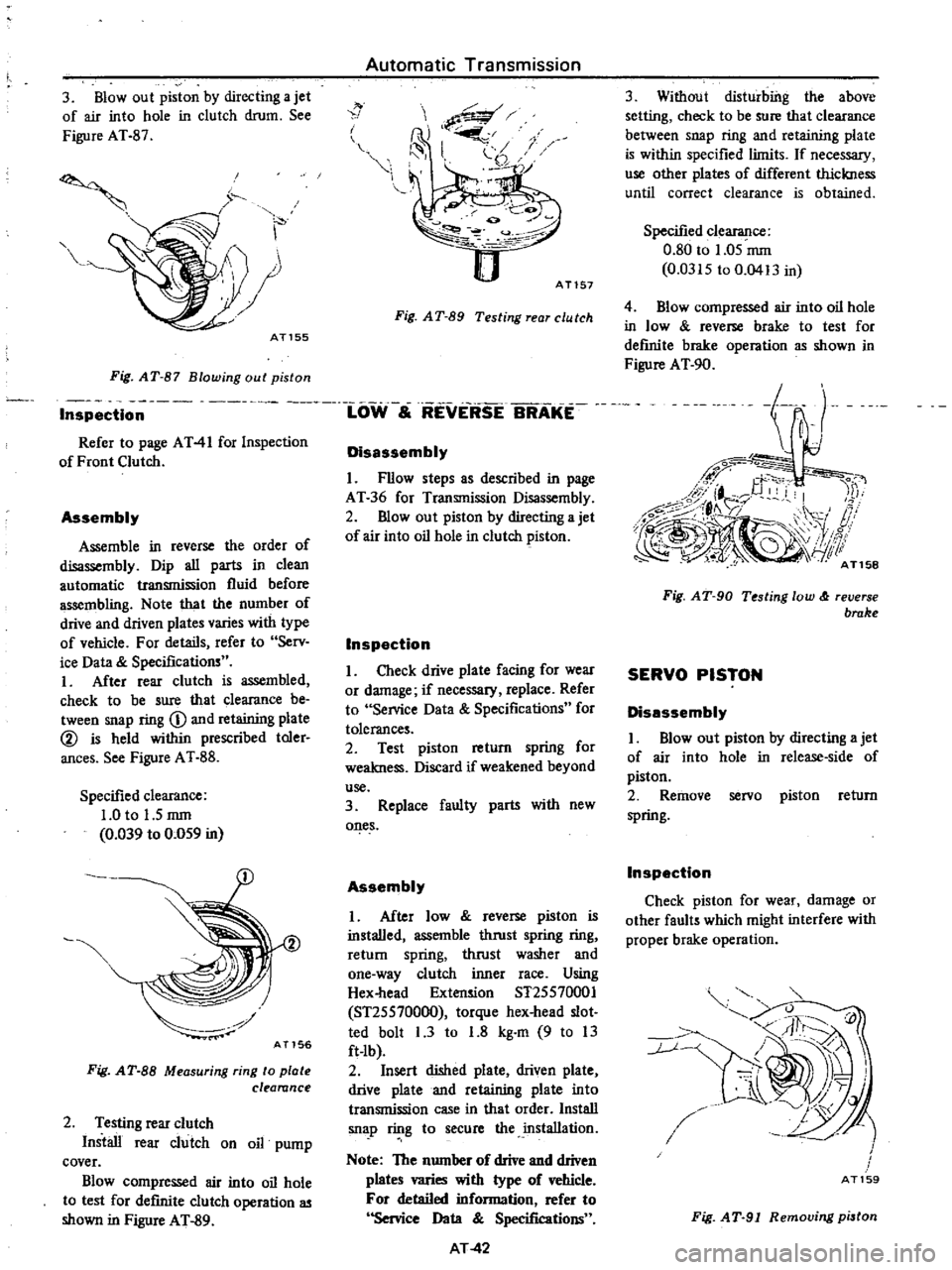
3
Blowout
piston
by
directing
a
jet
of
air
into
hole
in
clutch
drum
See
Figure
AT
87
AT155
V
i
J
i
j
Fig
AT
87
Blowing
out
piston
Automatic
Transmission
1
w
Ai
I
i
1
i
3
j
P2
0
AT157
Fig
A
T
89
Testing
rear
C
U
tch
Inspectl
ioW
S
REVERSE
BRAKE
Refer
to
page
AT41
for
Inspection
of
Front
Clutch
Assembly
Assemble
in
reverse
the
order
of
disassembly
Dip
all
parts
in
clean
automatic
transmission
fluid
before
assembling
Note
that
the
number
of
drive
and
driven
plates
varies
with
type
of
vehicle
F
or
details
refer
to
Serv
ice
Data
Specifications
I
After
rear
clutch
is
assembled
check
to
be
sure
that
clearance
be
tween
snap
ring
D
and
retaining
plate
l
is
held
within
prescribed
toler
ances
See
Figure
AT
88
Specified
clearance
1
0
to
1
5
rom
0
039
to
0
059
in
AT156
Fig
AT
SS
Measuring
ring
to
plate
clearance
2
Testing
rear
clutch
Install
rear
clutch
on
oil
pump
cover
Blow
compressed
air
into
oil
hole
to
test
for
defInite
clutch
operation
as
shown
in
Figure
AT
89
Disassembly
1
Fllow
steps
as
described
in
page
AT
36
for
Transmission
Disassembly
2
mow
out
piston
by
directing
a
jet
of
air
into
oil
hole
in
clutch
piston
Inspection
I
Check
drive
plate
facing
for
wear
or
damage
if
necessary
replace
Refer
to
Service
Data
Specifications
for
tolerances
2
Test
piston
return
spring
for
weakness
Discard
if
weakened
beyond
use
3
Replace
faulty
parts
with
new
ones
Assembly
I
After
low
reverse
piston
is
installed
assemble
thrust
spring
ring
retum
spring
thrust
washer
and
one
way
clutch
inner
race
Using
Hex
head
Extension
ST25570001
ST25570000
torque
hex
head
slot
ted
bolt
I
3
to
1
8
kg
m
9
to
13
ft
lb
2
Insert
dished
plate
driven
plate
drive
plate
and
retaining
plate
into
transmission
case
in
that
order
Install
sn
p
ring
to
secure
the
installation
Note
The
number
of
drive
and
driven
plates
wries
with
type
of
vehicle
For
detailed
information
refer
to
Service
Data
Specifications
AT42
3
Without
disturbiilg
the
above
setting
check
to
be
sure
that
clearance
between
snap
ring
and
retaining
plate
is
within
specified
limits
If
necessary
use
other
plates
of
different
thickness
until
correct
clearance
is
obtained
Specified
clearance
0
80
to
1
05
rom
0
0315
to
0
0413
in
4
Blow
compressed
air
into
oil
hole
in
low
reverse
brake
to
test
for
definite
brake
operation
as
shown
in
Figure
AT
90
Fig
AT
90
Testing
low
reverse
brake
SERVO
PISTON
Disassembly
I
Blowout
piston
by
directing
a
jet
of
air
into
hole
in
release
side
of
piston
2
Remove
servo
piston
return
spring
Inspection
Check
piston
for
wear
damage
or
other
faults
which
might
interfere
with
proper
brake
operation
v
r
0
111
Ll
7
J
I
AT159
Fig
AT
91
Removing
pi3ton
Page 308 of 537
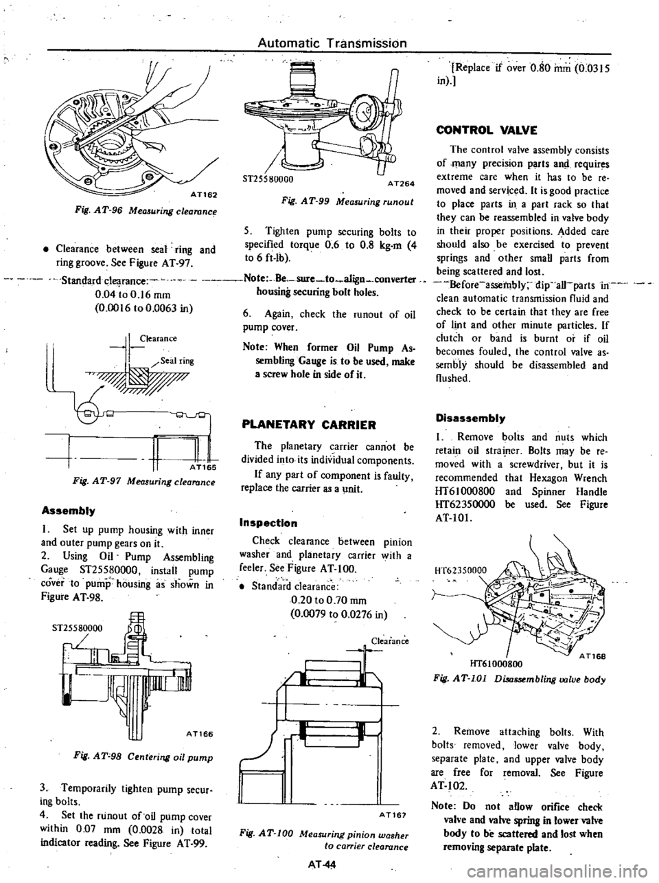
Fig
AT
96
Measuring
clearanc
Automatic
Transmission
6
u
ST255801JOO
AT264
Fig
AT
99
Measuring
runout
5
Tighten
pump
securing
bolts
to
specified
torque
0
6
to
0
8
kg
m
4
to
6
ft
Ib
Clearance
between
seal
ring
and
ring
groove
See
Figure
AT
97
Standarddearance
Note
Be
sure
to
a1ign
converter
0
04
io
0
16
mm
housing
securing
bolt
holes
0
0016
to
0
0063
in
6
Again
check
the
runout
of
oil
pump
cover
I
learance
Seal
ring
q
I
n
l
1
AT
5
Fig
AT
97
Measuring
clearance
Assembly
I
Set
up
pump
housing
with
inner
and
outer
pump
gears
on
it
2
Using
Oil
Pump
Assembling
Gauge
ST25580000
instail
pump
coverta
pump
housing
as
shown
in
Figure
A
T
98
ST
5
000
J
I
I
JL
AT166
Fig
AT
98
Centering
oil
pump
3
Temporarily
lighten
pump
secur
ing
bolts
4
Set
the
runout
of
oil
pump
cover
within
0
D7
mm
0
0028
in
total
indicator
reading
See
Figure
AT
99
Note
When
former
Oil
Pump
As
sembling
Gauge
is
to
be
used
make
a
screw
hole
in
side
of
it
PLANETARY
CARRIER
The
planetary
carrier
cannot
be
divided
into
its
individual
components
If
any
part
of
component
is
faulty
replace
the
carrier
as
a
unit
Inspection
Check
clearance
between
pinion
washer
and
planetary
carrier
with
a
feeler
See
Figure
AT
100
Standard
clearance
0
20
to
0
70
mm
0
0079
to
0
0276
in
Clearance
I
Jr
I
1
11
r
AT167
Fig
AT
100
Measuring
pinion
washer
to
ca
ier
clearance
AT
44
Replace
if
over
0
80
mm
0
0315
in
CONTROL
VALVE
The
control
valve
assembly
consists
of
many
preci
ion
parts
and
requir
s
extreme
care
when
it
has
to
be
reo
moved
and
serviced
It
is
good
practice
to
place
parts
in
a
part
rack
so
that
they
can
be
reassembled
in
valve
body
in
their
proper
positions
Added
care
should
also
be
exercised
to
prevent
springs
and
other
small
parts
from
being
scattered
and
lo
t
Before
assembly
dip
all
parts
in
clean
automatic
transmission
fluid
and
check
to
be
certain
that
they
are
free
of
lint
and
other
minute
particles
If
clutch
or
band
is
burnt
or
if
oil
becomes
fouled
the
control
valve
as
sembly
should
be
di
ssembled
and
flushed
Disassembly
I
Remove
bolts
and
nuts
which
retain
oil
trainer
Bolts
may
be
re
moved
with
a
screwdriver
but
it
is
recommended
that
Hexagon
Wrench
HT610oo800
and
Spinner
Handle
HT62350000
be
used
See
Figure
AT
101
HT61000800
Fig
AT
101
Disassembling
valve
body
2
Remove
attaching
bolts
With
bolts
removed
lower
valve
body
separate
plate
and
upper
valve
body
are
free
for
removal
See
Figure
AT
102
Note
Do
not
allow
orifice
check
vah
e
and
valve
spring
in
lower
valve
body
to
be
scattered
and
lost
when
removing
separate
plate
Page 313 of 537
In
these
cases
the
transmission
must
be
repaired
Notes
a
In
checking
oil
level
use
special
paper
cloth
to
handle
the
level
gauge
and
be
careful
not
to
let
the
scraps
of
paper
and
cloth
stick
to
the
gauge
b
Insert
the
gauge
fully
and
take
it
out
quickly
before
splashing
oil
adheres
to
the
gauge
Then
observe
the
level
c
Use
automatic
transmission
fluid
having
DEXRON
identifications
only
in
the
3N71B
automatic
trans
mission
d
Pay
attention
because
the
oil
to
be
used
differs
from
that
used
in
the
Nissan
Full
Automatic
TranSJTIis
sion
3N71A
Never
mix
the
oils
INSPECTION
AND
REPAIR
OF
OIL
LEAKAGE
When
oil
leakage
takes
place
the
portion
near
the
leakage
is
covered
with
oil
presenting
difficulty
in
detecting
the
spot
Therefore
the
places
where
oil
seals
and
gaskets
are
equipped
are
enumerated
below
11
Converter
housing
Rubber
ring
of
oil
pump
housing
Oil
seal
of
oil
pump
housing
Oil
seal
of
engine
crankshaft
Bolts
of
converter
housing
to
case
2
Trarismission
and
rear
extension
Junction
of
transm
ss
ion
and
rear
extension
J
Oil
cooler
tube
connectors
Oil
pan
Oil
pressure
inspection
holes
Refer
to
Figure
AT
il2
Mounting
portion
of
vacuum
dia
phragm
and
downshift
solenoid
Breather
and
oil
charging
pipe
Speedometer
pinion
sleeve
Oil
se
l
of
rear
extension
To
exactly
locate
the
place
of
oil
leaka
le
proceed
as
follows
Place
the
vehicle
in
a
pit
and
by
sampling
the
leaked
oil
determine
if
it
is
the
torque
converter
oil
The
torque
converter
oil
has
a
color
like
r
d
wine
So
it
is
easily
distinguished
from
engine
oil
or
gear
oil
Automatic
rransmission
Wipe
off
the
leaking
oil
and
dust
and
deiecl
the
spol
of
oil
eakage
l
se
nonflammable
organic
solve
t
s
ch
as
carbon
tetrachloride
for
wiping
Raise
the
oil
tcmperalure
by
op
erating
the
engine
and
shift
the
lever
to
D
to
increase
the
oil
pressure
The
spot
of
oil
lcakage
will
then
be
found
more
easily
Note
As
oil
leakage
from
the
breaih
er
does
not
take
place
except
when
running
at
high
speed
it
is
impos
sible
to
locate
this
leakage
with
vehicle
stationary
CHECKING
ENGINE
IDLING
REVOLUTION
The
engine
idling
revolution
should
be
properly
adjusted
If
the
engine
revolution
is
too
low
the
engine
does
not
operate
smoothly
and
if
too
high
a
strong
shock
or
creep
develops
when
changing
over
from
N
to
D
or
R
CHECKING
AND
ADJUSTING
KICK
DOWN
SWITCH
AND
DOWNSHIFT
SOLENOID
When
the
kickdown
operation
is
not
made
properly
or
the
speed
chang
ing
point
s
too
high
check
the
kick
down
switch
downshift
solenoid
and
wiring
between
them
When
the
igni
li
n
key
is
pqsitioned
a
t
the
I
st
stage
nd
the
accelerator
pedal
is
depressed
deeply
the
switch
contact
should
be
closed
and
the
solenoid
should
click
If
it
does
not
click
it
indicates
a
defect
Then
check
each
part
with
the
testing
instruments
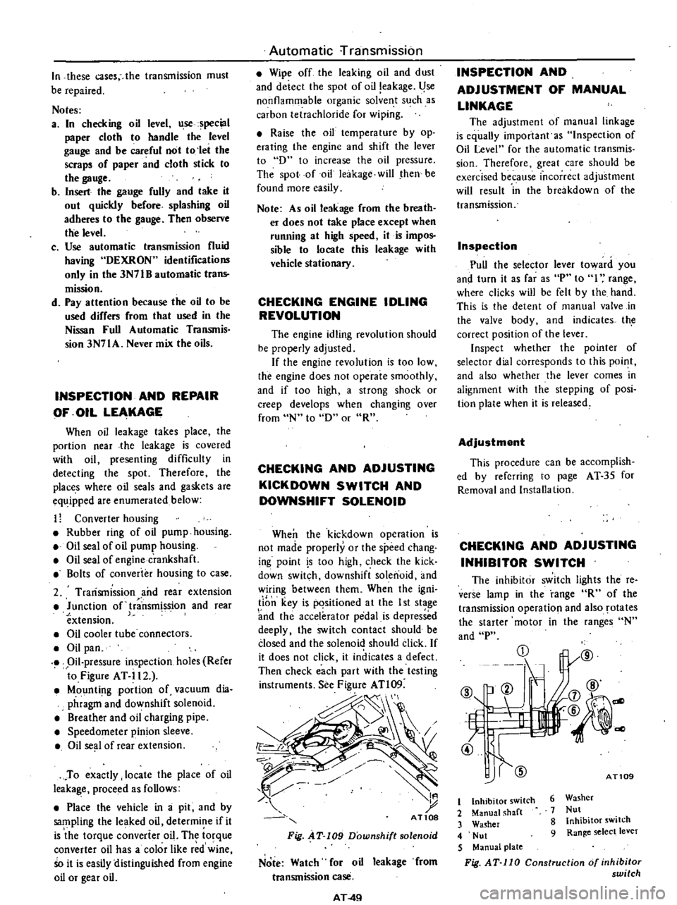
See
Figure
ATl09
d
I
t
AT10S
Fig
AT
109
Downshift
solenoid
Note
Watch
for
oil
leakage
from
transmission
case
AT
4Q
INSPECTION
AND
ADJUSTMENT
OF
MANUAL
LINKAGE
The
adjustmcnt
of
manual
linkage
is
equaUy
important
as
Inspection
of
Oil
Level
for
the
automatic
transmis
sion
Thereforc
great
care
should
be
exercised
because
incorrect
adjustment
will
rcsult
in
the
brcakdown
of
the
transmission
Inspection
Pull
the
selector
lever
toward
you
and
turn
it
as
far
as
P
to
I
range
wherc
clicks
will
be
felt
by
the
hand
This
is
the
detcnt
of
manual
valve
in
the
valve
body
and
indicates
th
correct
position
of
the
lever
Inspect
whether
the
pointer
of
selector
dial
corresponds
to
this
point
and
also
whether
the
lever
comes
in
alignment
with
the
stepping
of
posi
tion
plate
when
it
is
released
Adjustment
This
procedure
can
be
accomplish
ed
by
refcrring
to
page
AT
35
for
Removal
and
Installa
tion
CHECKING
AND
ADJUSTING
INHIBITOR
SWITCH
The
inhibitor
switch
lights
the
re
verse
lamp
in
the
range
R
of
the
transmission
operatio
l
and
also
rotates
the
starter
motor
in
the
ranges
N
and
P
CD
@
b
ell
If
L
t
7
4l
@
1l
j7
@
@
@
dl
AT109
6
Washer
7
Nut
8
Inhibitor
switch
9
Range
select
lever
t
Inhibitor
switch
2
Manual
shaft
3
Washer
4
Nut
5
Manual
plate
Fig
AT
110
Construction
of
inhibitor
switch
Page 383 of 537
REMOVAL
1
Removing
flare
nuts
on
both
ends
and
clips
effects
the
removal
of
brake
tube
and
brake
hose
2
Rear
brake
hose
can
be
removed
by
disconnecting
the
tube
and
then
turning
round
the
hose
Note
When
removing
brake
tubes
and
hoses
use
Flare
Nut
Torque
Wrench
GG943IOOOO
Never
use
an
OpeD
end
or
an
adjust
able
wrench
INSPECTION
1
Examine
all
hoses
for
swell
rubbing
marks
or
ozone
cracking
re
placing
those
found
with
any
of
above
badly
beyond
use
Also
inspect
end
fittings
and
be
sure
that
no
fluid
leak
through
staked
end
has
taken
place
replace
if
necessary
Hose
with
badly
rusted
fitting
should
also
be
replaced
with
a
new
one
2
Clean
all
tubes
to
remove
dust
and
dirt
with
isopropyl
alcohol
check
ing
for
collapse
wear
cracking
swell
or
rusting
Replace
if
foun
d
with
any
of
wove
Use
care
not
to
damage
brake
tubes
while
operation
Check
if
tubes
are
clamped
secure
ly
Mter
all
brake
lines
have
been
installed
retighten
aU
connections
if
necessary
to
assist
in
obtaining
correct
torque
In
retightening
at
front
wheel
cylinder
first
remove
hose
clamp
and
loosen
flare
nut
on
opposite
side
to
avoid
twisting
hose
Hold
pedal
as
far
downward
as
possible
80
kg
176
lb
or
more
examining
evidence
as
to
whether
fluid
is
leaking
through
brake
lines
or
con
nections
Leakage
in
any
manner
can
not
be
permitted
here
In
case
fluid
leaks
tightening
to
specified
torque
tighten
additionally
up
to
2
5
kg
m
J
8
ft
lb
Under
no
circumstances
should
not
be
tightened
over
2
5
kg
m
18
ft
Ib
torque
since
this
elongates
end
fitting
making
it
impossible
to
reuse
brake
tube
Under
no
circumstances
should
rear
brake
hose
and
3
way
connector
be
retightened
over
specified
torques
In
Brake
System
stead
replace
copper
washer
with
a
new
one
after
checking
for
sign
of
damage
on
seating
surface
Never
reuse
an
old
copper
washer
INSTALLATION
Brake
hose
Front
brake
hose
In
installing
brake
hose
first
jack
up
vehicle
to
take
off
the
weight
of
vehicle
from
wheels
so
that
suspension
is
in
rebound
Steering
wheel
should
also
be
kept
in
straight
ahead
position
To
connect
brake
line
first
connect
brake
hose
to
wheel
cylinder
with
the
specified
torque
Tightening
torque
1
7
to
2
0
kg
m
12
to
14
ft
Ib
Then
secure
brake
hose
to
the
bracket
with
lock
plate
so
as
not
to
twist
or
abnormally
bend
the
hose
Note
After
connecting
brake
hose
at
both
eiuIs
pay
keen
attention
not
to
twist
the
hose
when
additional
tightening
is
required
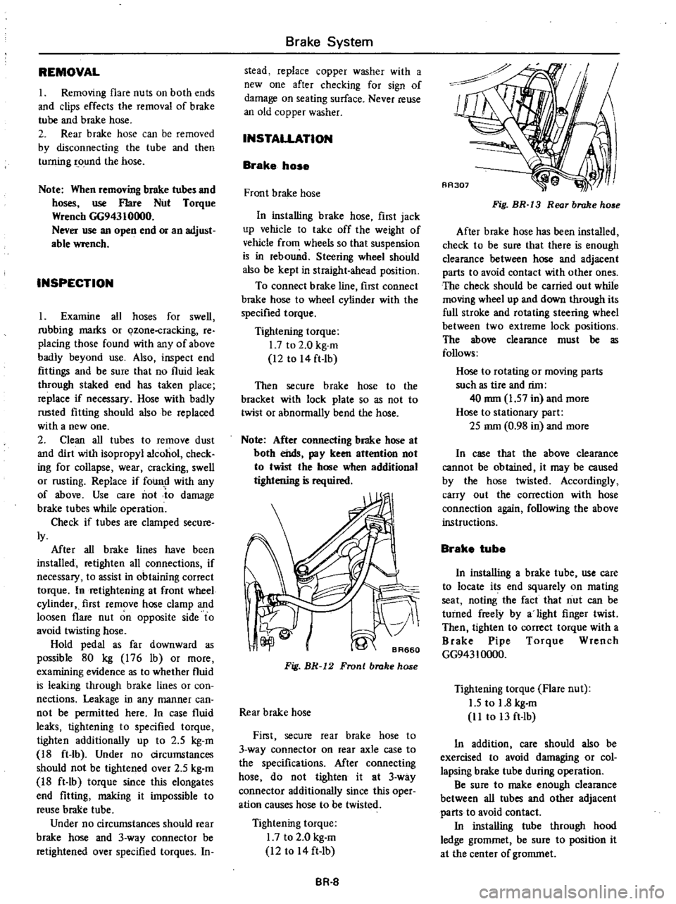
Fig
BR
12
Front
brake
hose
Rear
brake
hose
First
secure
rear
brake
hose
to
3
way
connector
on
rear
axle
case
to
the
specifications
Mter
connecting
hose
do
not
tighten
it
at
3
way
connector
additionally
since
this
oper
ation
causes
hose
to
be
twisted
Tightening
torque
I
7
to
2
0
kg
m
12
to
14
ft
Ib
BR
8
Fig
BR
13
Rear
brake
ho
e
After
brake
hose
has
been
installed
check
to
be
sure
that
there
is
enough
clearance
between
hose
and
adjacent
parts
to
avoid
contact
with
other
ones
The
check
should
be
carried
out
while
moving
wheel
up
and
down
through
its
full
stroke
and
rotating
steering
wheel
between
two
extreme
lock
positions
The
wow
clearance
must
be
as
follows
Hose
to
rotating
or
mOving
parts
such
as
tire
and
rim
40
mm
1
57
in
and
more
Hose
to
stationary
part
2S
mm
0
98
in
and
more
In
case
that
the
above
clearance
cannot
be
obtained
it
may
be
caused
by
the
hose
twisted
Accordingly
carry
out
the
correction
with
hose
connection
again
following
the
above
instructions
Brake
tube
In
installing
a
brake
tube
use
care
to
locate
its
end
squarely
on
mating
seat
noting
the
fact
that
nut
can
be
turned
freely
by
a
light
finger
twist
Then
tighten
to
correct
torque
with
a
Brake
Pipe
Torque
Wrench
GG943
10000
Tightening
torque
Flare
nut
1
5
to
1
8
kg
m
11
to
13
ft
Ib
In
addition
care
should
also
be
exercised
to
avoid
damaging
or
col
lapsing
brake
tube
during
operation
Be
sure
to
make
enough
clearance
between
all
tubes
and
other
adjacent
parts
to
avoid
contact
In
installing
tube
through
hood
ledge
grommet
be
sure
to
position
it
at
the
center
of
grommet
Page 388 of 537
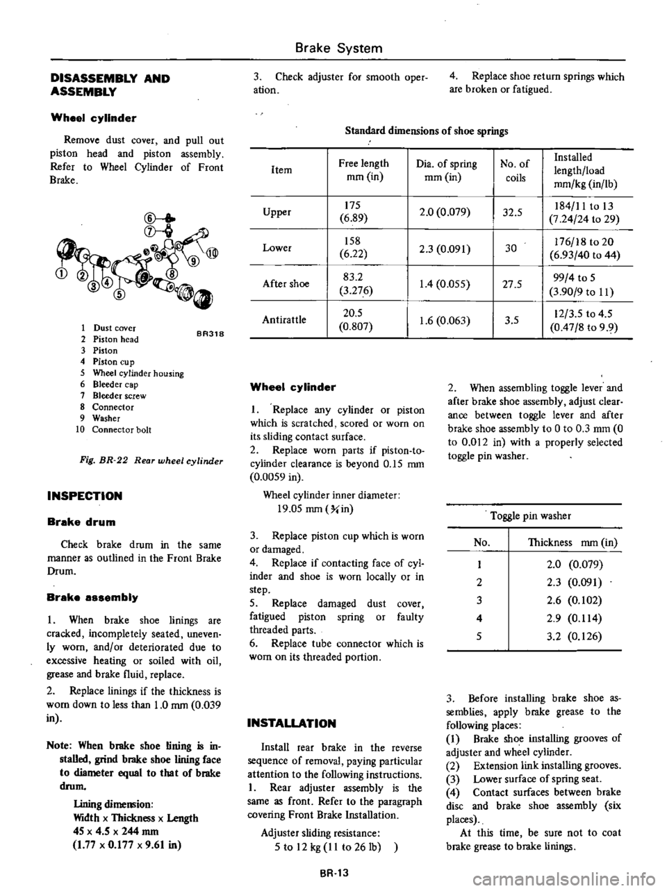
DISASSEMBLY
AND
ASSEMBLY
Wheel
cylinder
Remove
dust
cover
and
pull
out
piston
head
and
piston
assembly
Refer
to
Wheel
Cylinder
of
Front
Brake
CD
l
ID
345
0
1
Dust
cover
2
Piston
head
3
Piston
4
Piston
Cll
p
5
Wheel
cylinder
housing
6
Bleeder
cap
7
Bleeder
screw
8
Connector
9
Washer
10
Connector
bolt
BR318
Fig
BR
22
Rear
wheel
cylinder
INSPECTION
Brake
drum
Check
brake
drum
in
the
same
manner
as
outlined
in
the
Front
Brake
Drum
Brake
assembly
I
When
brake
shoe
linings
are
cracked
incompletely
seated
uneven
ly
worn
andlor
deteriorated
due
to
excessive
heating
or
soiled
with
oil
grease
and
brake
fluid
replace
2
Replace
linings
if
the
thickness
is
WOol
down
to
less
than
1
0
rom
0
039
in
Note
When
brake
shoe
lining
is
in
stalled
grind
brake
shoe
lining
face
to
diameter
equal
10
lha
I
of
brake
drom
Lining
dimemion
Width
x
Thickness
x
Length
4S
x
4
5
x
244
rom
1
77
x
0
177
x
9
61
in
Brake
System
3
Check
adjuster
for
smooth
oper
ation
4
Replace
shoe
return
springs
which
are
broken
or
fatigued
Standard
dimensions
of
shoe
springs
Dia
of
spring
No
of
Installed
Free
length
lengthlload
Item
mOl
in
mOl
in
coils
mmlkg
in
lb
175
2
0
0
079
32
5
184
11
to
13
Upper
6
89
7
24
24
to
29
158
2
3
0
091
30
176
18
to
20
Lower
6
22
6
93
40
to
44
83
2
1
4
0
055
27
5
99
4
to
S
After
shoe
3
276
3
90
9
to
II
20
5
1
6
0
063
3
5
12
3
S
to
4
5
AntiratUe
0
807
0
47
8
to
9
9
Wheel
cylinder
I
Replace
any
cylinder
or
piston
which
is
scratched
scored
or
worn
on
its
sliding
contact
surface
2
Replace
worn
parts
if
piston
to
cylinder
clearance
is
beyond
O
IS
rom
0
00S9
in
Wheel
cylinder
inner
diameter
19
0S
rom
Xin
3
Replace
piston
cup
which
is
worn
or
damaged
4
Replace
if
contacting
face
of
cyl
inder
and
shoe
is
worn
locally
or
in
step
5
Replace
damaged
dust
cover
fatigued
piston
spring
or
faulty
threaded
parts
6
Replace
tube
connector
which
is
worn
on
its
threaded
portion
INSTALLATION
Install
rear
brake
in
the
reverse
sequence
of
removal
paying
particular
attention
to
the
following
instructions
I
Rear
adjuster
assembly
is
the
same
as
front
Refer
to
the
paragraph
covering
Front
Brake
Installation
Adjuster
sliding
resistance
S
to
12
kg
II
to
261b
BR
13
2
When
assembling
toggle
lever
and
after
brake
shoe
assembly
adjust
clear
ance
between
toggle
lever
and
after
brake
shoe
assembly
to
0
to
0
3
mOl
0
to
0
012
in
with
a
properly
selected
toggle
pin
washer
Toggle
pin
washer
No
Thickness
rom
in
I
2
0
0
079
2
2
3
0
091
3
2
6
0
102
4
2
9
0
114
S
3
2
0
126
3
Before
installing
brake
shoe
as
semblies
apply
brake
grease
to
the
following
places
1
Brake
shoe
installing
grooves
of
adjuster
and
wheel
cylinder
2
Extension
link
installing
grooves
3
Lower
surface
of
spring
seat
4
Contact
surfaces
between
brake
disc
and
brake
shoe
assembly
six
places
At
this
time
be
sure
not
to
coat
brake
grease
to
brake
linings
Page 468 of 537
Body
Electrical
System
WINDSHIELD
WIPER
AND
WASHER
REMOVAL
AND
INSTALLATION
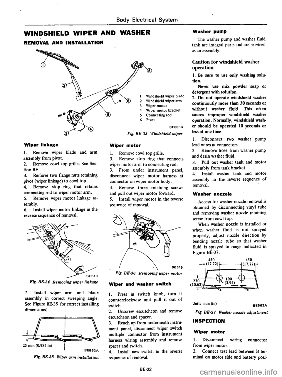
Wiper
linkage
I
Remove
wiper
blade
and
arm
assembly
from
pivot
2
Remove
cowl
top
grille
See
Sec
tion
BF
3
Remove
two
flange
nuts
retaining
pivot
wiper
linka
e
to
cowl
top
4
Remove
stop
ring
that
retains
connecting
rod
to
wiper
motor
arm
5
Remove
wiper
motor
linkage
as
sembly
6
Install
wiper
motor
linkage
in
the
reverse
sequence
of
removal
Fig
BE
34
Removing
wiper
linkage
7
Install
wiper
arm
and
blade
assembly
in
correct
sweeping
angle
See
Figure
BE
35
for
correct
installing
dimensions
JC
I
i
25
mm
0
984
in
r
BE862A
Fig
BE
35
Wip
J
arm
irutallation
1
Windshield
wiper
blade
2
Windihield
wiper
arm
3
Wiper
motor
4
Wiper
motor
bracket
5
Connecting
rod
6
Pivot
BE685B
Fig
BE
33
Wind
hield
wiper
Wiper
motor
I
Remove
cowl
top
grille
3
Remove
stop
ring
that
connects
wiper
motor
arm
to
connecting
rod
3
From
under
instrument
panel
disconnect
wiper
motor
harness
at
connector
on
wiper
motor
body
4
Remove
three
retaining
screws
and
pull
out
wiper
motor
forward
5
Install
wiper
motor
in
the
reverse
sequence
of
removal
Fig
BE
36
Wiper
and
washer
switch
1
Press
in
switch
knob
turn
it
counterclockwise
and
pull
it
out
of
switch
2
Unscrew
escutcheon
and
remove
escutcheon
and
spacer
3
Reach
up
from
underneath
instru
ment
panel
disconnect
wiper
switch
multiple
connector
from
instrument
harness
wiring
assembly
and
remove
spacer
and
switch
4
Install
new
switch
in
the
reverse
sequence
of
removal
BE
23
Washer
pump
The
washer
pump
and
washer
fluid
tank
are
integral
parts
and
are
serviced
as
an
assembly
Caution
for
windshield
waBher
operation
I
Be
sure
to
use
only
washing
solu
tion
Never
use
mix
powder
soap
or
detergent
with
solution
2
Do
not
operate
windshield
washer
continuously
more
than
30
seconds
or
without
washer
fluid
This
often
causes
improper
windshield
washer
operation
Normally
windshield
wash
er
should
be
operated
10
seconds
or
less
at
one
time
I
Disconnect
two
washer
pump
lead
wires
at
connectors
2
Remove
hose
from
washer
pump
and
drain
washer
fluid
3
Pull
out
washer
tank
and
motor
assembly
from
tank
bracket
4
Install
washer
tank
and
motor
assembly
in
the
reverse
sequence
of
removal
Washer
nozzele
Access
for
washer
nozzle
removal
is
obtained
by
disconnecting
vinyl
tube
and
removing
washer
nozzle
retaining
screw
from
cowl
top
When
washer
nozzle
is
installed
or
when
washer
fluid
is
not
sprayed
properly
adjust
nozzle
direction
by
bending
nozzle
tube
so
that
washer
fluid
is
sprayed
in
range
indicated
in
Figure
BE
37
450
450
j217
72
r
l
1772
Ii
L
1
00
Li
L
J
270
1
to
63
3
94
1
Unit
nun
in
BE863A
Fif
BE
37
Waaher
nozzle
adjuatment
INSPECTION
Wiper
motor
I
Disconnect
wiring
connector
from
wiper
motor
2
Connect
test
lead
between
B
ter
minal
on
motor
ide
and
battery
posi