clutch DATSUN PICK-UP 1977 Service Manual
[x] Cancel search | Manufacturer: DATSUN, Model Year: 1977, Model line: PICK-UP, Model: DATSUN PICK-UP 1977Pages: 537, PDF Size: 35.48 MB
Page 12 of 537
General
Information
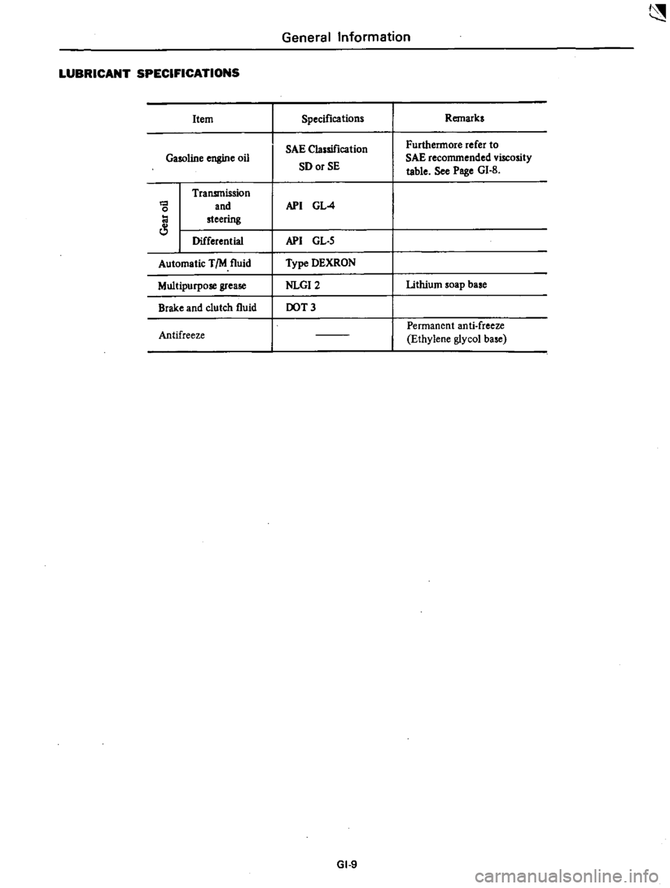
LUBRICANT
SPECIFICATIONS
Item
Specifications
Remarks
SAE
Classification
Furthermore
refer
to
Gasoline
engine
oil
SD
or
SE
SAE
recommended
viscosity
table
See
Poge
GI
B
Transmission
and
API
GL
4
0
steering
Differential
API
GL
S
Automatic
TIM
fluid
Type
DEXRON
Multipurpose
grea
NLGI2
lithium
soap
base
Brake
and
clutch
fluid
DOT
3
Permanent
anti
freeze
Antifreeze
Ethylene
glycol
ba
e
GI
9
Page 42 of 537
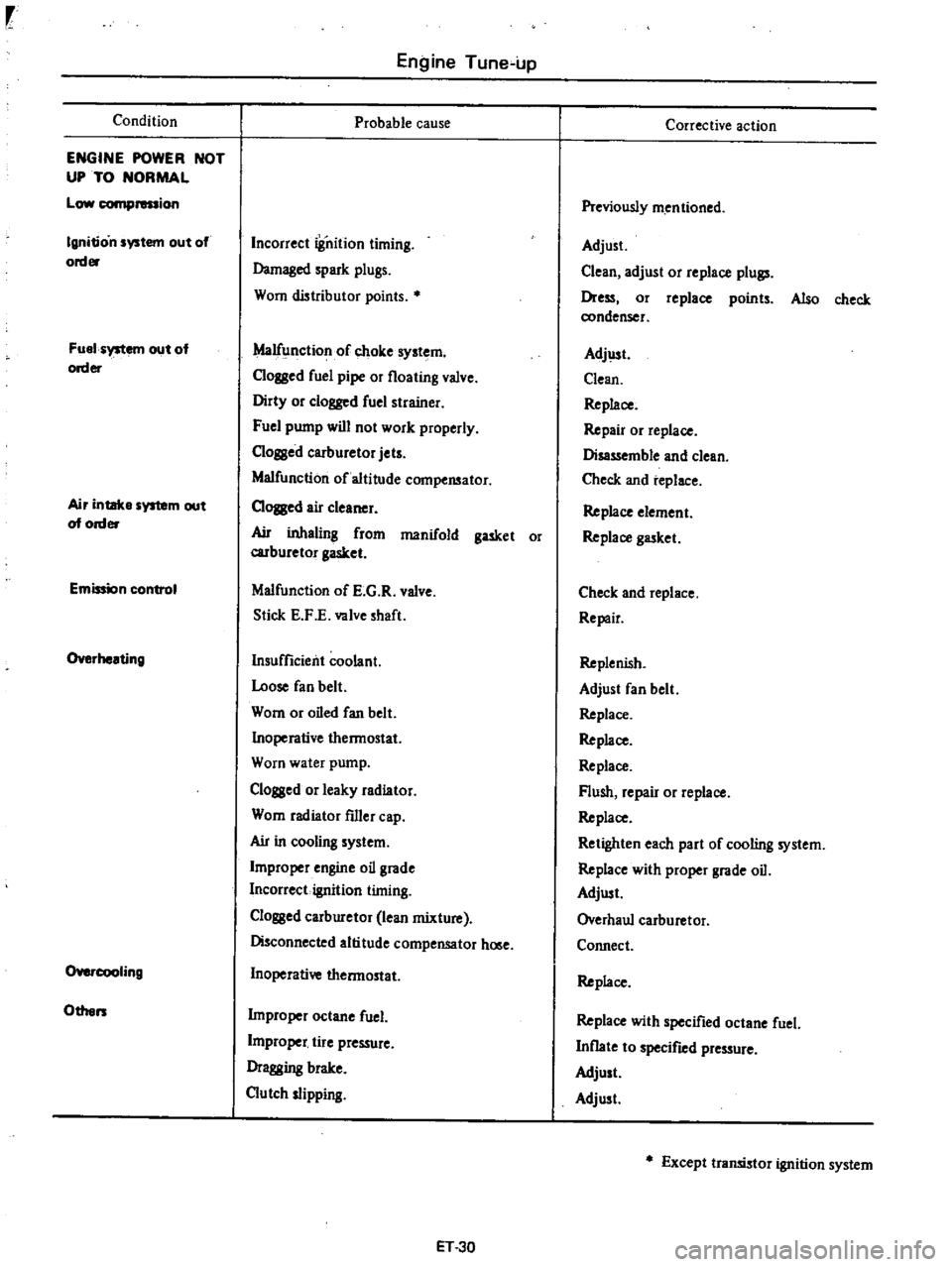
Condition
ENGINE
POWER
NOT
UP
TO
NORMAL
Low
compression
Ignition
system
out
of
order
Fuel
system
out
of
order
Air
intake
system
out
of
order
Emission
control
Overheating
O
cooIing
Others
Engine
Tune
up
Probable
cause
Incorrect
iSnition
timing
Damaged
spark
plugs
Worn
distributor
points
Malfunction
of
choke
system
Clogged
fuel
pipe
or
floating
valve
Dirty
or
clogged
fuel
strainer
Fuel
pump
will
not
work
properly
C10ssed
carburetor
jets
Malfunction
of
altitude
compensator
CIOJBed
air
cleaner
Ail
inhaling
from
manifold
gasket
or
carburetor
gasket
Malfunction
of
E
G
R
valve
Stick
E
F
E
valve
shaft
Insufficient
coolant
Loose
fan
belt
Worn
or
oiled
fan
belt
Inoperative
thermostat
Worn
water
pump
Clogged
or
leaky
radiator
Worn
radiator
filler
cap
Ail
in
cooling
system
Improper
engine
oil
grade
Incorrect
ignition
timing
Clossed
carburetor
lean
mixture
Disconnected
altitude
compensator
hOlle
Inoperative
thermostat
Improper
octane
fuel
L
j
tire
pressure
Dragging
brake
Clutch
slipping
ET
30
Corrective
action
Previously
mentioned
Adjust
Clean
adjust
or
replace
plull
Dress
or
replace
points
Also
check
condenser
Adj
lst
Clean
Replace
Repair
or
replace
Disassemble
and
clean
Check
and
replace
Replace
element
Replace
gasket
Check
and
replace
Repair
Replenish
Adjust
fan
belt
Replace
Replace
Replace
Flush
repair
or
replace
Replace
Retighten
each
part
of
cooling
system
Replace
with
proper
grade
oil
Adjust
Overhaul
carburetor
Connect
Replace
Replace
with
specified
octane
fuel
Inflate
to
specified
pressure
Adjust
Adjust
Except
transistor
ignition
system
Page 43 of 537
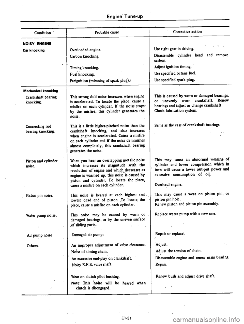
Condition
NOISY
ENGINE
Car
knocking
Mechanical
knocking
Crankshaft
bearing
Imocking
Connecting
rod
bearing
knocking
Piston
and
cylinder
noise
Piston
pin
noise
Water
pump
noise
Air
pump
noise
Others
Engine
Tune
up
Probable
cause
Overloaded
engine
Carbon
knocking
Timing
knocking
Fuel
knocking
Preignition
misusing
of
spark
plug
This
strong
dull
noise
increases
when
engine
is
accelerated
To
locate
the
place
cause
a
misfire
on
each
cylinder
If
the
noise
stops
by
the
misfire
this
cylinder
generates
the
noise
This
is
a
little
higher
pitched
noise
than
the
crankshaft
Imocking
and
also
increases
when
engine
is
accelerated
Cause
a
misfire
on
each
cylinder
and
if
the
noise
deminishes
almost
completely
this
crankshaft
bearing
generates
the
noise
When
you
hear
an
overlapping
metalic
noise
which
increases
its
magnitude
with
the
revolution
of
engine
and
which
decreases
as
engine
is
warmed
up
this
noise
is
caused
by
piston
and
cylinder
To
locate
the
place
cause
a
misfire
on
each
cylinder
This
noise
is
heared
at
each
highest
and
lowest
dead
end
of
piston
To
locate
the
place
cause
a
misfire
on
each
cylinder
This
noise
may
be
caused
by
worn
or
damaged
earings
or
by
the
uneven
surface
of
sliding
parts
Damaged
air
pump
An
improper
adjustment
of
valve
clearance
Noise
of
timing
chain
An
excessive
end
play
on
crankshaft
Noisy
E
F
E
valve
shaft
Wear
on
clutch
pilot
bushing
Note
This
noise
will
be
heared
when
clutch
is
disengaged
ET31
Corrective
action
Use
right
gear
in
driving
Disassemble
cylinder
head
and
remove
carbon
Adjust
ignition
timing
Use
specified
octane
fuel
Use
specified
spark
plug
This
is
caused
by
worn
or
damaged
bearings
or
unevenly
worn
crankshaft
Renew
bearings
and
adjust
or
change
crankshaft
Check
lubrication
system
Same
as
the
case
of
crankshaft
bearings
This
may
cause
an
abnormal
wearing
of
cylinder
and
lower
compression
which
in
turn
will
cause
a
lower
out
put
power
and
excessive
consumption
of
oil
Overhaul
engine
This
may
cause
a
wear
on
piston
pin
or
piston
pin
hole
Renew
piston
and
piston
pin
assembly
Replace
water
pump
with
a
new
one
Repair
or
replace
Adjust
Adjust
the
tension
of
chain
Disassemble
engine
and
renew
main
bearing
Repair
Renew
bush
and
adjust
drive
shaft
Page 49 of 537
r
I
I
PRELIMINARY
CLEANING
AND
INSPECTION
DISASSEMBL
Y
PRELIMINARY
CLEANING
AND
INSt
ECTION
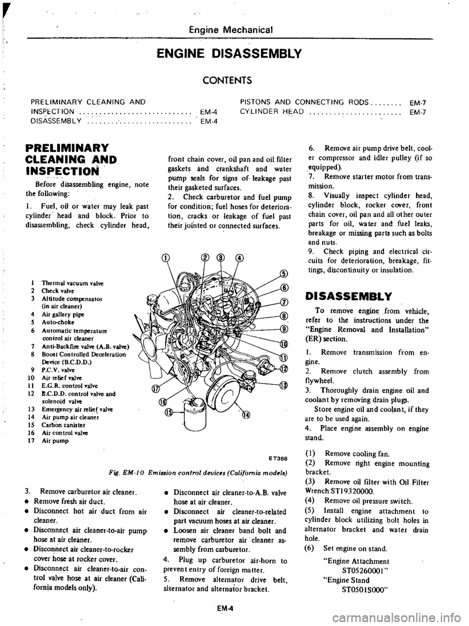
Before
disassembling
engine
note
the
following
I
Fuel
oil
or
water
may
leak
past
cylinder
head
and
block
Prior
to
disassembling
check
cylinder
head
1
1ltermal
vacuum
valve
2
Check
valve
3
Altitude
compensator
in
air
cleaner
4
Air
gallery
pipe
S
Auto
choke
6
Automatic
temperature
control
air
cleaner
7
Anti
8ackfire
valve
A
B
valve
8
Boost
Controlled
Deceleration
Device
Bee
D
D
9
P
c
v
valve
to
Air
relief
valve
11
E
G
R
control
valve
12
B
C
D
D
control
valve
and
solenoid
valve
13
Emergency
air
relief
valve
14
Air
pump
air
cleaner
IS
Carbon
canister
16
Air
control
valve
11
Air
pump
Engine
Mechanical
ENGINE
DISASSEMBLY
CONTENTS
EM
4
EM
4
PISTONS
AND
CONNECTING
RODS
CYLINDER
HE
AD
EM
7
EM
7
front
chain
cover
oil
pan
and
oil
filter
gaskets
lInd
crankshaft
and
water
pump
seals
for
signs
of
leakage
past
their
gasketed
surfaces
2
Check
carburetor
and
fuel
pump
for
condition
fuel
hoses
for
deteriora
tion
cracks
or
leakage
of
fuel
past
their
jointed
or
connected
surfaces
Fig
EM
0
Emiuion
control
devic
s
California
mod
18
E
T366
3
Remove
carburetor
air
cleaner
Remove
fresh
air
duct
Disconnect
hot
air
duct
from
air
cleaner
Disconnect
air
cleaner
to
air
pump
hose
at
air
cleaner
Disconnect
air
cleanef
to
rocker
cover
hose
at
rocker
cover
Disconnect
air
cIeaner
to
air
con
trol
valve
hose
at
air
cleaner
Cali
fornia
models
only
Disconnect
air
cleaner
to
A
B
valve
hose
at
air
cleaner
Disconnect
air
cleaner
to
related
part
vacuum
hoses
at
air
cleaner
Loosen
air
cleaner
band
bolt
and
remove
carburetor
air
cleaner
as
sembly
from
carburetor
4
Plug
up
carburetor
air
horn
to
prevent
entry
of
foreign
matter
5
Remove
alternator
drive
belt
alternator
and
alternator
bracket
EM
4
6
Remove
air
pump
drive
belt
cool
er
compressor
and
idler
pulley
if
so
equipped
7
Remove
starter
motor
from
trans
mission
8
Visually
inspect
cylinder
head
cylinder
block
rocker
C
Ner
front
chain
cover
oil
pan
and
all
other
outer
parts
for
oil
water
and
fuel
leaks
breakage
or
missing
parts
such
as
bolts
and
nuts
9
Check
piping
and
electrical
cir
cuits
for
deterioration
breakage
fit
tings
discontinuity
or
insulation
DISASSEMBLY
To
remove
engine
from
vehicle
refer
to
the
instructions
under
the
Engine
Removal
and
Installation
ER
section
I
Remove
transmission
from
en
gine
2
Remove
clutch
assembly
from
flywheeL
3
Thoroughly
drain
engine
oil
and
coolan
t
by
removing
drain
plugs
Store
engine
oil
and
coolant
if
they
are
to
be
used
again
4
Place
engine
assembly
on
engine
stand
I
Remove
cooling
fan
2
Remove
right
engine
mounting
bracket
3
Remove
oil
filter
with
Oil
Filter
Wrench
STI9320000
4
Remove
oil
pressure
swi
tch
5
Install
engine
attachment
to
cylinder
block
utilizing
bolt
holes
in
alternator
bracket
and
water
drain
hole
6
Set
engine
on
stand
Engine
Attachment
ST05260001
Engine
Stand
ST050I
SOOO
Page 65 of 537
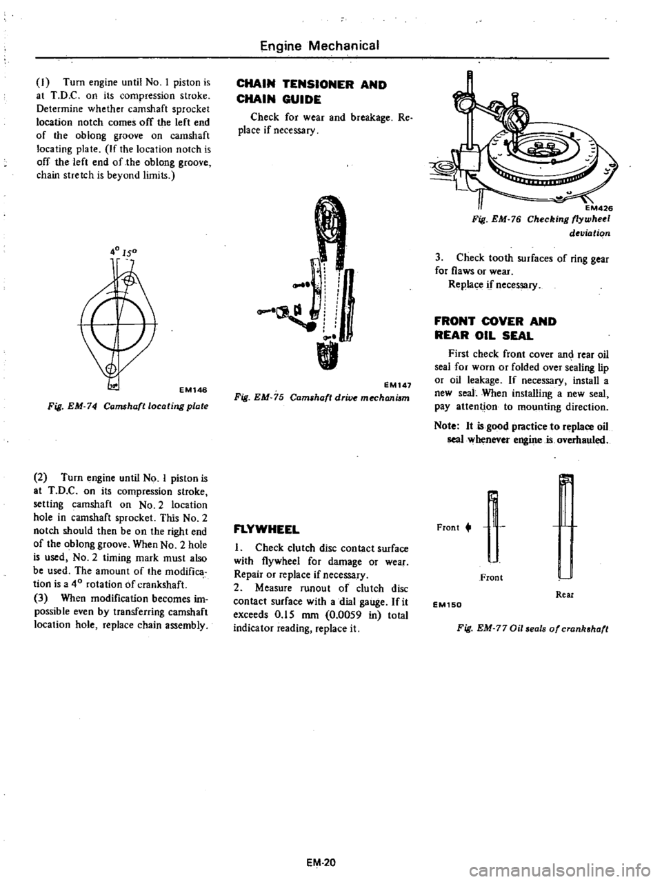
I
Turn
engine
until
No
I
piston
is
at
T
D
C
on
its
compression
stroke
Determine
whether
camshaft
sprocket
location
notch
comes
off
the
left
end
of
the
oblong
groove
on
camshaft
locating
plate
If
the
location
notch
is
off
the
left
end
of
the
oblong
groove
chain
stretch
is
beyond
limits
40150
EMl46
Fig
EM
74
Camshafllocating
plate
2
Turn
engine
until
No
I
piston
is
at
T
D
C
on
its
compression
stroke
setting
camshaft
on
No
2
location
hole
in
camshaft
sprocket
This
No
2
notch
should
then
be
on
the
right
end
of
the
oblong
groove
When
No
2
hole
is
used
NO
2
timing
mark
must
also
be
used
The
amount
of
the
modifica
tion
is
a
40
rotation
of
crankshaft
3
When
modification
becomes
im
possible
even
by
transferring
camshaft
location
hole
replace
chain
assembly
Engine
Mechanical
CHAIN
TENSIONER
AND
CHAIN
GUIDE
Check
for
wear
and
breakage
Re
place
if
necessary
r
I
L
EM147
Fig
EM
75
Cam
haft
dri
mechanilm
FLYWHEEL
I
Check
clutch
disc
contact
surface
with
flywheel
for
damage
or
wear
Repair
or
replace
if
necessary
2
Measure
runout
of
clutch
disc
contact
surface
with
a
dial
gauge
fit
exceeds
0
15
mm
0
0059
in
total
indicator
reading
replace
it
EM
20
EM426
Fig
EM
76
Checking
flywheel
deviation
3
Check
tooth
surfaces
of
ring
gear
for
flaws
or
wear
Replace
if
necessary
FRONT
COVER
AND
REAR
OIL
SEAL
First
check
front
cover
an
rear
oil
seal
for
worn
or
folded
over
sealing
lip
or
oil
leakage
If
necessary
install
a
new
seal
When
installing
a
new
seal
pay
attenti
on
to
mounting
direction
Note
It
is
good
practice
to
replace
oil
seal
whenever
engine
is
overhauled
Frant
t
r
r
J
I
Front
Real
EM150
Fig
EM
77
Oil
eals
of
crank
haft
Page 71 of 537
30
Install
heatshieid
plate
on
mani
fold
assembly
31
Install
air
gallery
pipe
on
ex
haust
manifold
32
Install
manifold
gasket
and
manifold
assembly
on
cylinder
head
Tightening
torque
1
2to
1
6kg
m
8
7
to
11
6
ft
lb
33
Install
blow
by
gas
pipe
on
cyl
inder
block
and
tighten
with
rear
engine
slinger
34
Install
thermostat
housing
gas
ket
thermostat
housing
and
thermo
stat
35
Install
thermal
vacuum
valve
on
thermostat
housing
Before
installing
apply
a
liquid
packing
slightly
to
the
threads
36
Install
FJ
C
D
bracket
on
cylin
der
head
37
Install
E
G
R
passage
and
E
G
R
valve
on
intake
manifold
38
Connect
E
G
R
tube
to
E
G
R
tube
and
exhaust
manifold
39
Install
check
valve
on
air
gallery
pipe
40
Install
air
cleaner
bracket
on
intake
manifold
41
Install
air
control
valve
on
air
cleaner
bracket
California
models
42
Install
vacuum
and
fuel
tubes
combined
on
cylinder
head
43
Install
distributor
assembly
44
Install
heatshield
plate
joint
seat
and
carburetor
Carbure10r
tightening
torque
0
5
to
1
0
kg
m
3
6
to
7
2
ft
lb
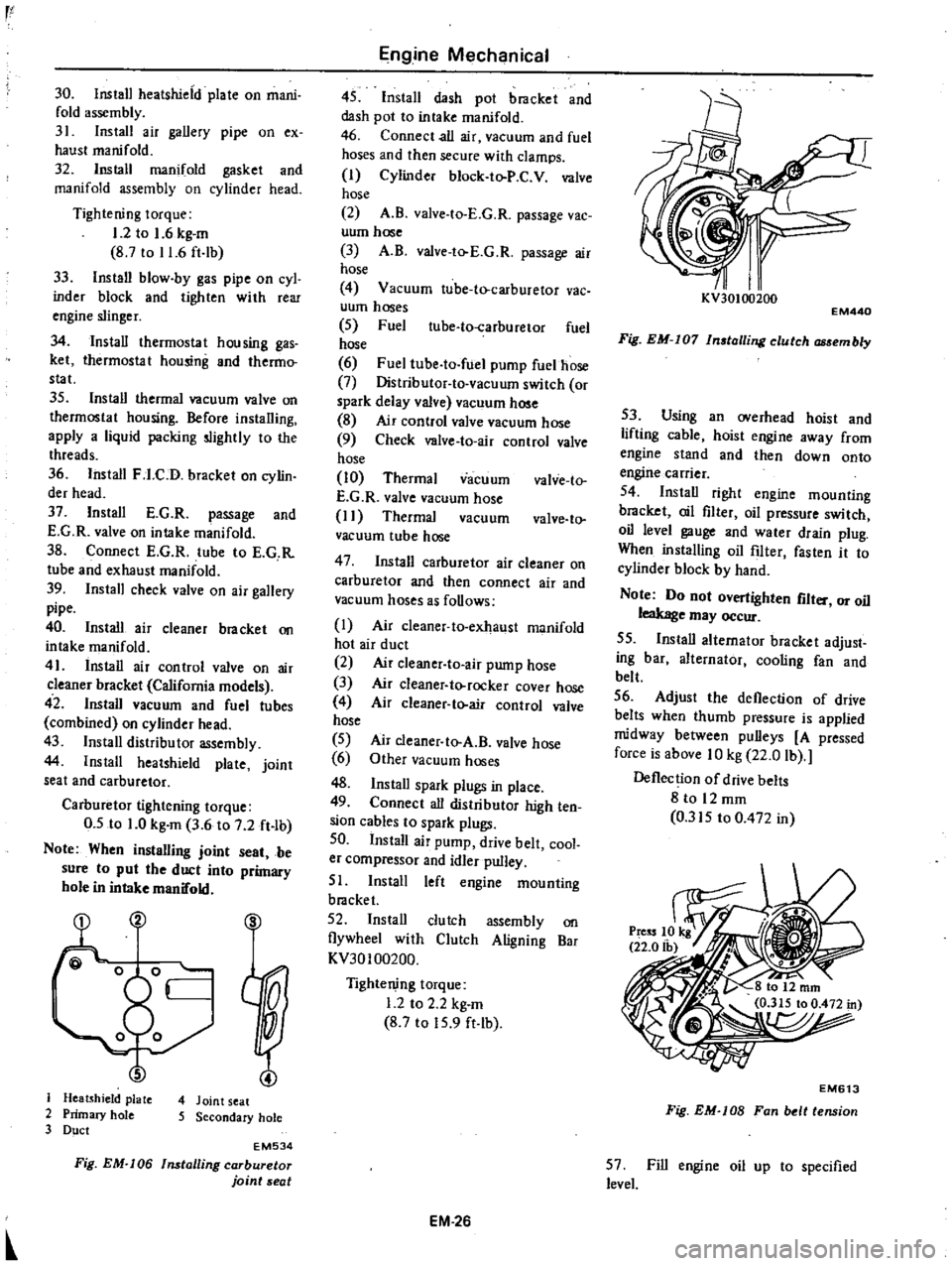
Note
When
instalUng
joint
seat
be
sure
to
put
the
duct
into
primary
hole
in
intake
manifold
S
J
Heatshield
plate
4
Joint
seat
2
Primary
hole
5
Secondary
hole
3
Duct
EM534
Fig
EM
I06
Installing
carburetor
joint
seat
Engine
Mechanical
45
Install
dash
pot
bracket
and
dash
pot
to
intake
manifold
46
Connect
all
air
vacuum
and
fuel
hoses
and
then
secure
with
clamps
I
Cylinder
block
to
P
C
V
valve
hose
2
A
B
valve
to
E
G
R
passage
vac
uum
hose
3
A
B
valve
to
E
G
R
passage
air
hose
4
Vacuum
tube
to
carburetor
vac
uum
hoses
5
Fuel
ube
to
carburetor
fuel
hose
6
Fuel
tube
to
fuel
pump
fuelhose
7
Distributor
to
vacuum
switch
or
spark
delay
valve
vacuum
hose
8
Air
control
valve
vacuum
hose
9
Check
valve
to
air
control
valve
hose
10
Thermal
vacuum
valve
to
E
G
R
valve
vacuum
hose
I
I
Thermal
vacuum
valve
to
vacuum
tube
hose
47
Install
carburetor
air
cleaner
on
carburetor
and
then
connect
air
and
vacuum
hoses
as
follows
I
Air
cleaner
to
exhaust
manifold
hot
air
duct
2
Air
c1eaner
to
air
pump
hose
3
Air
cleaner
to
rocker
cover
hose
4
Air
cleaner
to
air
control
valve
hose
5
6
48
Install
spark
plugs
in
place
49
Connect
all
distributor
high
ten
sion
cables
to
spark
plugs
50
Install
air
pump
drive
belt
cool
er
compressor
and
idler
pulley
51
Install
left
engine
mounting
bracket
52
Install
clutch
assembly
on
flywheel
with
Clutch
Aligning
Bar
KV30100200
Air
cleaner
to
A
B
valve
hose
Other
vacuum
hoses
Tightening
torque
1
2
to
2
2
kg
m
8
7
to
15
9
ft
lb
EM
26
I
I
KV30100200
EM440
Fig
EM
I07
In
talling
clutch
embly
53
Using
an
overhead
hoist
and
lifting
cable
hoist
engine
away
from
engine
stand
and
then
down
onto
engine
carrier
54
Install
right
engine
mounting
bracket
oil
filter
oil
pressure
switch
oil
level
gauge
and
water
drain
plug
When
installing
oil
filter
fasten
it
to
cylinder
block
by
hand
Note
Do
not
overtighten
flit
or
oil
leakage
may
occur
55
Install
alternator
bracket
adjust
ing
bar
alternator
cooling
fan
and
belt
56
Adjust
the
deflection
of
drive
belts
when
thumb
pressure
is
applied
midway
between
pulleys
A
pressed
force
is
above
10
kg
22
0
lb
Deflection
of
drive
belts
8
to
12
mm
0
315
to
0
472
in
EM613
Fig
EM
lOB
Fan
belt
tension
57
Fill
engine
oil
up
to
specified
level
Page 74 of 537
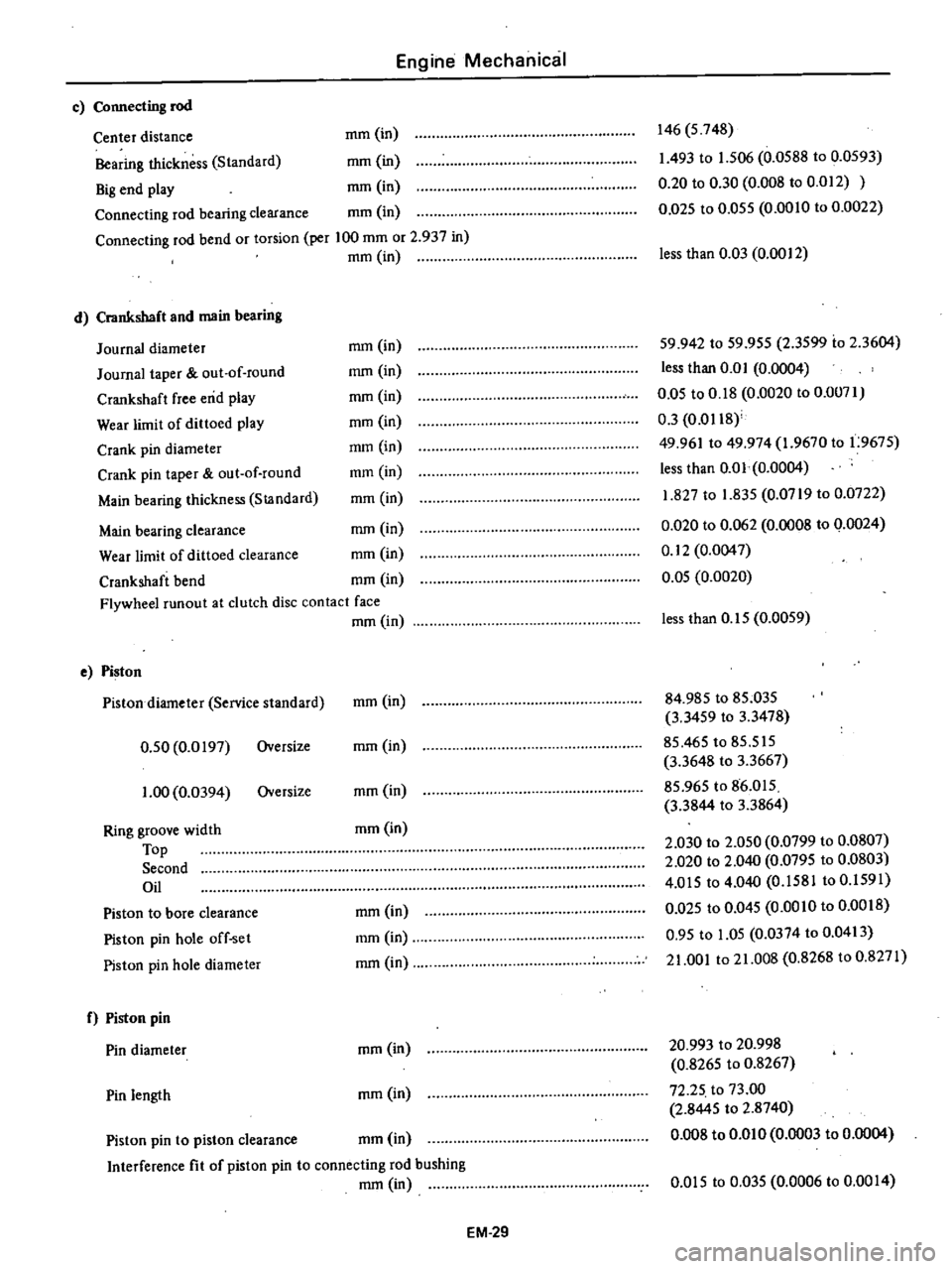
Engine
Mechanical
c
Connecting
rod
Center
distance
mm
in
Bearing
thickness
Standard
mm
in
Big
end
play
mm
in
Connecting
rod
bearing
clearance
mm
in
Connecting
rod
bend
or
torsion
per
100
mm
or
2
937
in
mm
in
d
Crankshaft
and
main
bearing
Journal
diameter
Journal
taper
out
of
round
Crankshaft
free
end
play
Wear
limit
of
dittoed
play
Crank
pin
diameter
Crank
pin
taper
out
of
round
Main
bearing
thickness
StJlndard
146
5
748
1
493
to
1
506
0
0588
to
0
0593
0
20
to
0
30
0
008
to
0
012
0
D25
to
0
055
0
0010
to
0
0022
less
than
0
03
0
0012
mm
in
mm
in
mm
in
mm
in
mm
in
mm
in
mm
in
59
942
to
59
955
2
3599
io
2
3604
less
than
0
0
I
0
0004
0
05
to
0
18
0
0020
to
0
0071
0
3
0
0118
49
961
to
49
974
1
9670
to
1
9675
less
than
0
01
0
0004
1
827
to
1
835
0
0719
to
0
0722
0
020
to
0
062
0
0008
to
0
0024
0
12
0
0047
0
05
0
0020
Main
bearing
clearance
mm
in
Wear
limit
of
dittoed
clearance
mm
in
Crankshaft
bend
mm
in
Flywheel
runout
at
clutch
disc
contact
face
mm
in
e
Piston
Pistondiarneter
Service
standard
0
50
0
0197
Oversize
1
00
0
0394
Oversize
Ring
groove
width
Top
Second
Oil
Piston
to
bore
clearance
Piston
pin
hole
off
set
Piston
pin
hole
diameter
f
Piston
pin
Pin
diameter
Pin
length
less
than
0
15
0
0059
mm
in
84
985
to
85
035
3
3459
to
3
3478
85
465
to
85
515
3
3648
to
3
3667
85
965
to
86
015
3
3844
to
3
3864
2
030
to
2
050
0
0799
to
0
0807
2
020
to
2
040
0
0795
to
0
0803
4
015
to
4
040
0
1581
to
0
1591
0
Q25
to
0
045
0
0010
to
0
0018
0
95
to
1
05
0
0374
to
0
0413
21
001
to
21
008
0
8268
to
0
8271
mm
in
mm
in
mm
in
mm
in
mm
in
mm
in
mm
in
20
993
to
20
998
0
8265
to
0
8267
72
25
to
73
00
2
8445
to
2
8740
0
008
to
om
0
0
0003
to
0
0004
mm
in
Piston
pin
to
piston
clearance
mm
in
Interference
fit
of
piston
pin
to
connecting
rod
bushing
mm
in
om
5
to
0
035
0
0006
to
0
00
I
4
EM
29
Page 83 of 537
r
Engine
Mechanical
Tool
number
For
Reference
No
Description
use
page
or
tool
name
Unit
mm
in
on
Figure
No
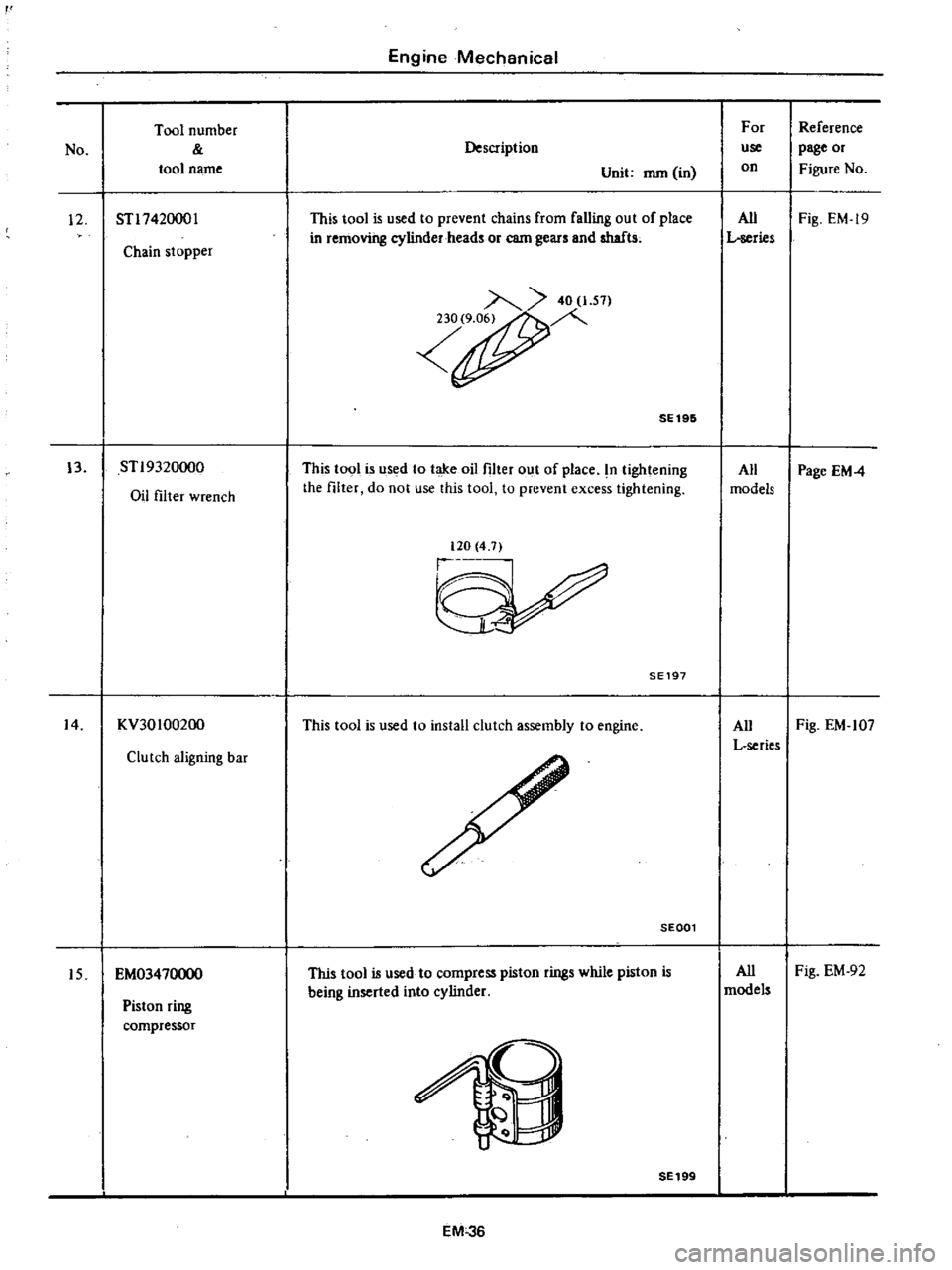
12
STl742000l
This
tool
is
used
to
prevent
chains
from
falling
out
of
place
All
Fig
EM
19
in
removing
cylinder
heads
or
earn
gears
and
shafts
L
series
Chain
stopper
40
1
S1
r
SE196
13
STl9320oo0
This
tool
is
used
to
take
oil
filter
out
of
place
n
tightening
All
Page
EM4
Oil
filter
wrench
the
filter
do
not
use
this
tool
to
prevent
excess
tightening
models
120
4
7
SE197
14
KV30100200
This
tool
is
used
to
install
clutch
assembly
to
engine
All
Fig
EM
107
L
series
Clutch
aligning
bar
SEGOl
Piston
ring
compressor
This
tool
is
used
to
compress
piston
rings
while
piston
is
being
inserted
into
cylinder
All
Fig
EM
92
models
15
EM03470000
2
SE199
EM
36
Page 171 of 537

DESCRIPTION
OPERATION
CONSTR
UCTI
ON
REMOVAL
DISASSEMBL
Y
CLEANING
AND
INSPECTION
TERMINAL
FIELD
COIL
BRUSHES
AND
BRUSH
LEAD
WIRE
BRUSH
SPRING
TENSION
ARMATURE
ASSEMBLY
DESCRIPTION
The
function
of
the
starting
system
which
consists
of
the
battery
ignition
switch
starting
motor
and
solenoid
is
to
crank
the
engine
The
electrical
energy
is
supplied
from
the
battery
the
solenoid
completes
the
circuit
to
operate
the
starling
motor
and
then
the
motor
carries
out
the
actual
crank
ing
of
the
engine
Engine
Electrical
System
STARTING
MOTOR
CONTENTS
EE
4
EE
6
EE
7
EE
7
EE
7
EE
8
EE
8
EE
B
EE
B
EE
B
EE
B
OVERRUNNING
CLUTCH
ASSEMBLY
BRUSH
HOLDER
TEST
FOR
GROUND
BEARING
METAL
MAGNETIC
SWITCH
ASSEMBLY
ASSEMBLY
TEST
PERFORMANCE
TEST
MAGNETIC
SWITCH
ASSEMBLY
TEST
SERVICE
DATA
AND
SPECIFICATIONS
TROUBLE
DIAGNOSES
AND
CORRECTIONS
5
@
EE
9
EE
9
EE
9
EE
9
EE
9
EE
9
EE
9
EE
O
EE
EE
11
I
Brush
2
Field
coil
3
Magnetic
switch
4
Pludgcr
5
Torsion
spring
6
Shifll
r
7
Overrunning
clutch
8
Pinion
9
Armature
9
EE315
Fig
EE
5
Sectioool
view
of
slarting
motor
Sl14
180B
EE
4
Page 173 of 537
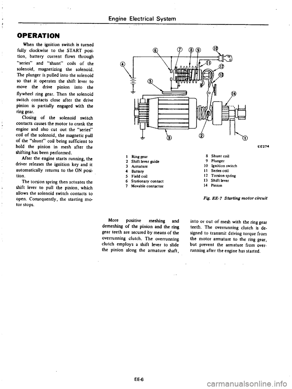
OPERATION
When
the
ignition
switch
turned
fully
clockwise
to
the
START
posi
tion
battery
current
flows
through
series
and
shunt
coils
of
the
solenoid
magnetizing
the
solenoid
The
plunger
is
pulled
into
the
solenoid
so
that
it
operates
the
shift
lever
to
move
the
drive
pinion
into
the
flywheel
ring
gear
Then
the
solenoid
switch
contacts
close
after
the
drive
pinion
is
partially
engaged
with
the
ring
gear
Closing
of
the
solenoid
switch
contacts
c
uses
the
motor
to
crank
the
engine
and
also
cut
out
the
series
coil
of
the
solenoid
the
magnetic
pull
of
the
shunt
coil
being
sufficient
to
hold
the
pinion
in
mesh
after
the
shifting
has
been
performed
After
the
engine
starts
running
the
driver
releases
the
ignition
key
and
it
automatically
returns
to
the
ON
posi
tion
The
torsion
spring
then
actuates
the
shift
lever
to
pull
the
pinion
which
allows
the
solenoid
swi
tch
contacts
to
open
Consequently
the
starting
mo
tor
stops
Engine
Electrical
System
I
I
Ring
gear
2
Shift
lever
guide
3
Armature
4
Battery
5
Field
coil
6
Stationary
contact
7
Monble
contactor
More
positive
meshing
and
demeshing
of
the
pinion
and
the
ring
gear
teeth
are
secured
by
means
of
the
overrunning
clutch
The
overruIUling
clutch
employs
a
shift
lever
to
slide
the
pinion
along
the
armature
shaft
EE
6
F
l
cp
o
r
1
I
I
W
m
EE274
8
Shunt
coil
9
Plunger
10
Ignition
switch
11
Series
coil
12
Torsion
spring
13
Shift
lever
14
Pinion
Fig
EE
7
Starting
motor
circuit
into
or
out
of
mesh
with
the
ring
gear
teeth
The
overrunning
clutch
is
de
signed
to
transmit
driving
torque
from
the
motor
armature
to
the
ring
gear
but
prevent
the
armature
from
over
running
after
the
engine
has
started