air condition DATSUN PICK-UP 1977 Service Manual
[x] Cancel search | Manufacturer: DATSUN, Model Year: 1977, Model line: PICK-UP, Model: DATSUN PICK-UP 1977Pages: 537, PDF Size: 35.48 MB
Page 521 of 537
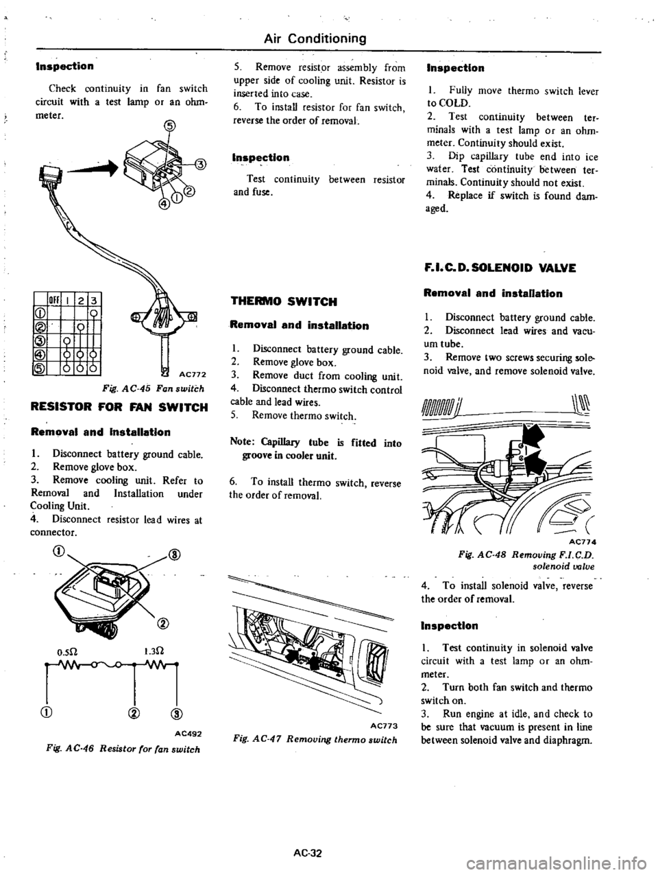
Inspection
Check
continuiry
in
fan
switch
circuit
with
a
test
lamp
or
an
ohm
meter
I
011
I
2
3
ICD
Tt
tt
AC772
Fig
AC
45
Fan
switch
RESISTOR
FOR
FAN
SWITCH
Removal
and
Installation
I
Disconnect
battery
ground
cable
2
Remove
glove
box
3
Remove
cooling
unit
Refer
to
Removal
and
Installation
under
Cooling
Unit
4
Disconnect
resistor
lead
wires
at
connector
@
O
sn
I
3n
CD
00
@
AC492
Fig
AC
46
Resistor
for
fan
switch
Air
Conditioning
5
Remove
resistor
assembly
from
upper
side
of
cooling
unit
Resistor
is
inserted
into
case
6
To
install
res
istor
for
fan
switch
reverse
the
order
of
removaL
Inspection
Test
continuity
between
resistor
and
fuse
THERMO
SWITCH
Removal
and
installation
1
Disconnect
battery
ground
cable
2
Remove
glove
box
3
Remove
duct
from
cooling
unit
4
Disconnect
thermo
switch
control
cable
and
lead
wires
5
Remove
thermo
switch
Note
Capillary
lube
is
fitted
into
groove
in
cooler
unit
6
To
install
thermo
switch
reverse
the
order
of
removal
I
I
AC773
Fig
AC
47
Removing
thermo
switch
AC
32
Inspection
I
Fully
move
thermo
swirch
lever
to
COLD
2
Test
continuity
between
ter
minals
with
a
test
tamp
or
an
ohm
meter
Continuity
should
exist
3
Dip
capillary
tube
end
into
ice
water
Test
continuity
between
ter
minals
Continuity
should
not
exist
4
Replace
if
switch
is
found
dam
aged
F
I
C
D
SOLENOID
VALVE
Removal
and
installation
I
Disconnect
battery
ground
cable
2
Disconnect
lead
wires
and
vacu
um
tube
3
Remove
two
screws
securing
sole
noid
valve
and
remove
solenoid
valve
AC77
4
Fig
AC
48
Removing
F
l
C
D
solenoid
valve
4
To
install
solenoid
valve
reverse
the
order
of
removal
Inspection
1
Test
continuity
in
solenoid
valve
circuit
with
a
test
lamp
or
an
ohm
meter
2
Turn
both
fan
switch
and
thermo
switch
on
3
Run
engine
at
idle
and
check
to
be
sure
that
vacuum
is
present
in
line
between
solenoid
valve
and
diaphragm
Page 522 of 537
DESCR
IPTIDN
COMPRESSOR
CLUTCH
REMOVAL
INSTAllATION
DISASSEMBLY
ASSEMBLY
INSPECTION
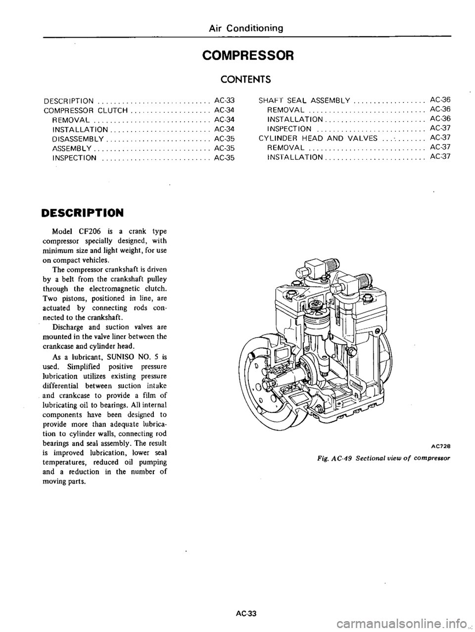
DESCRIPTION
Model
CF206
is
a
crank
type
compressor
specially
designed
with
minimum
size
and
light
weight
for
use
on
compact
vehicles
The
compressor
crankshaft
is
driven
by
a
belt
from
the
crankshaft
pulley
through
the
electromagnetic
clutch
Two
pistons
positioned
in
line
are
actuated
by
connecting
rods
coo
nected
to
the
crankshaft
Discharge
and
suction
valves
are
mounted
in
the
valve
liner
between
the
crankcase
and
cylinder
head
As
a
lubricant
SUNlSO
NO
5
is
used
Simplified
positive
pressure
lubrication
utilizes
existing
pressure
differential
between
suction
intake
and
crankcase
to
provide
a
film
of
lubricating
oil
to
bearings
All
internal
components
have
been
designed
to
provide
more
than
adequate
lubrica
tion
to
cylinder
walls
connecting
rod
bearings
and
seal
assembly
The
result
is
improved
lubrication
lower
seal
temperatures
reduced
oil
pumping
and
a
reduction
in
the
number
of
moving
parts
Air
Conditioning
COMPRESSOR
AC33
AC34
AC34
AC34
AC35
AC
35
AC35
CONTENTS
SHAFT
SEAL
ASSEMBLY
REMOVAL
INSTAllATION
INSPECTION
CYLINDER
HEAD
AND
VALVES
REMOVAL
INSTAllATION
AC36
AC36
AC36
AC37
AC37
AC37
AC37
AC728
Fig
AC
49
Sectional
view
of
compressor
AC33
Page 523 of 537
Air
Conditioning
1foo
1t
1
t7
LV
I
1
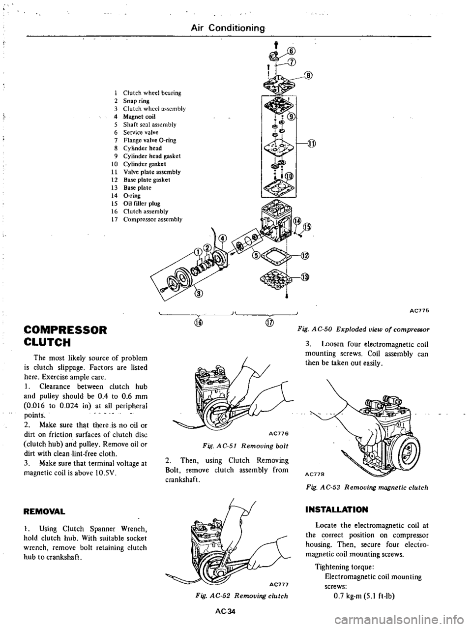
Clutch
wheel
bearing
2
Snap
ring
3
Clutch
wheel
assembly
4
Magnet
coil
5
Shaft
seal
assembly
6
Service
valve
7
Flange
valve
O
ring
8
Cylinder
head
9
Cylinder
head
gasket
10
Cylinder
gasket
11
Valve
plate
assembly
12
Base
plate
gasket
13
Base
plate
14
O
ring
15
Oil
filler
plug
16
Clutch
assembly
17
Compressor
assembly
COMPRESSOR
CLUTCH
The
most
likely
source
of
problem
is
clutch
slippage
Factors
are
listed
here
Exercise
ample
care
I
Clearance
between
clutch
hub
and
pulley
should
be
0
4
to
0
6
mm
0
016
to
0
024
in
at
all
peripheral
points
2
Make
sure
that
there
is
no
oil
or
dirt
on
friction
surfaces
of
clutch
disc
clutch
hub
and
pulley
Remove
oil
or
dirt
with
clean
lint
free
cloth
3
Make
sure
that
terminal
voltage
at
magnetic
coil
is
above
IO
5V
REMOVAL
I
Using
Clutch
Spanner
Wrench
hold
clutch
hub
With
suitable
socket
wrench
remove
bolt
retaining
clutch
hub
to
crankshaft
H
@
@
AC776
Fig
AC
51
Remouing
bolt
2
Then
using
Clutch
Removing
Bolt
remove
clutch
assembly
from
cmnkshaft
Fig
AC
52
Removing
clutch
AC34
AC775
Fig
A
C
50
Exploded
view
of
compressor
3
Loosen
four
electromagnetic
coil
mounting
screws
Coil
assembly
can
then
be
taken
out
easily
Fig
A
C
53
Removing
magnetic
clutch
INSTALLATION
Locate
the
electromagnetic
coil
at
the
correct
position
on
compressor
housing
Then
secure
four
electro
magnetic
coil
mounting
screws
Tightening
torque
Electromagnetic
coil
mounting
screws
0
7
kg
m
5
1
ft
Ib
Page 524 of 537
2
Install
the
clutch
assembly
on
the
crankshaft
Note
Key
should
be
set
on
crank
shaft
before
installing
clutch
assem
bly
3
Using
Clutch
Spanner
Wrench
hold
clutch
hub
With
socket
wrench
secure
clutch
hub
securing
bolt
Tightening
torque
Clutch
hub
securing
bolt
1
5
kg
m
II
ft
lb
DISASSEMBLY
1
Remove
two
snap
rings
retaining
bearing
They
are
located
inside
of
clutch
wheel
AC500
Fig
AC
54
Removing
snap
rings
2
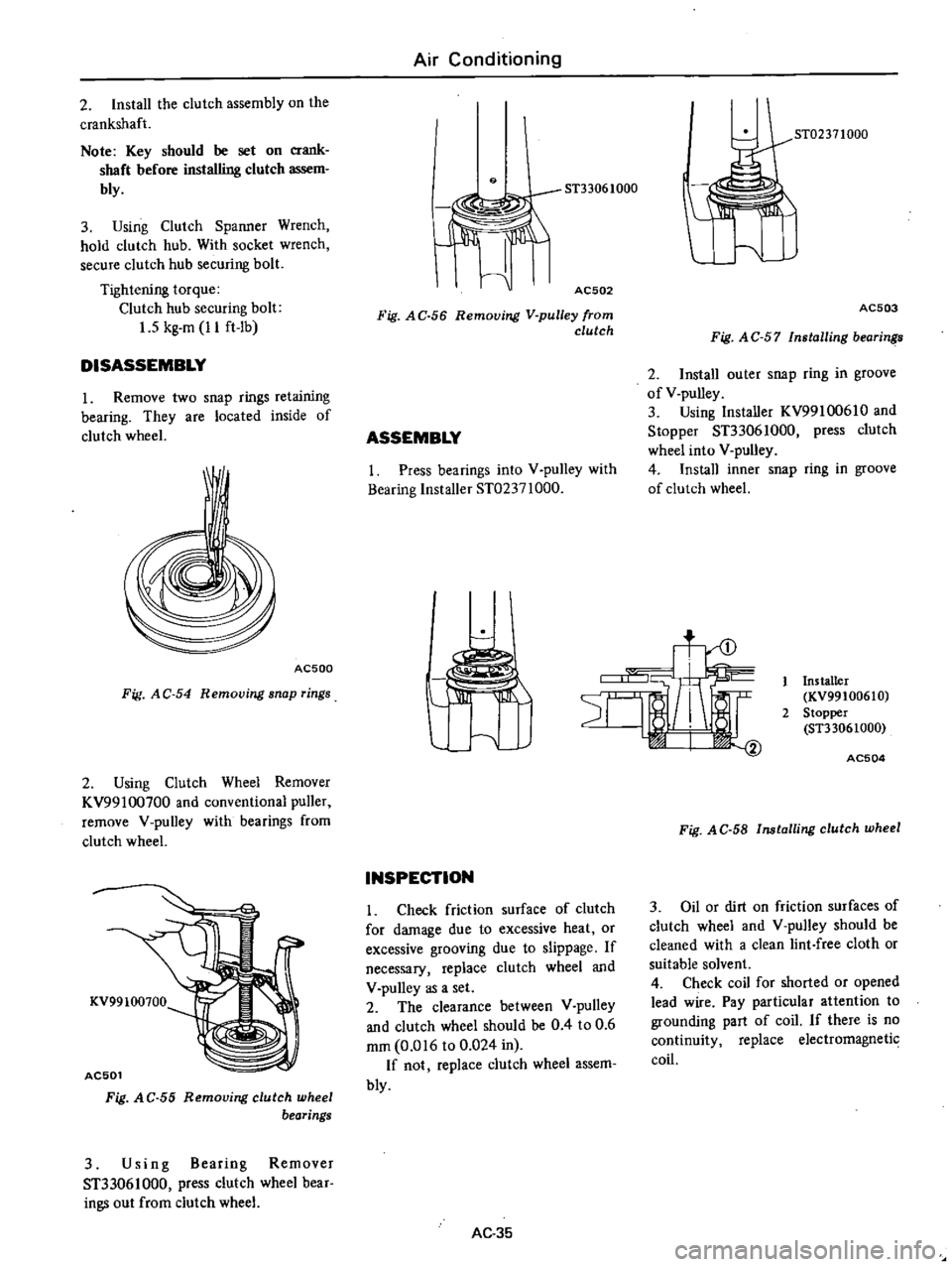
Using
Clutch
Wheel
Remover
KV99100700
and
conventional
puller
remove
V
pulley
with
bearings
from
clutch
wheel
KV99100700
AC501
Fig
A
C
55
Removing
clutch
wheel
bearings
3
Using
Bearing
Remover
ST33061000
press
clutch
wheel
bear
ings
out
from
clutch
wheel
Air
Conditioning
9
AC502
Fig
AC
56
Removing
V
pulley
from
clutch
ASSEMBLY
I
Press
bearings
into
V
pulley
with
Bearing
Installer
ST02371000
ST02371000
AC503
Fig
A
C
57
Installing
bearin
2
Install
outer
snap
ring
in
groove
of
V
pulley
3
Using
Installer
KV99100610
and
Stopper
ST33061000
press
clutch
wheel
into
V
pulley
4
Install
inner
snap
ring
in
groove
of
clutch
wheel
t
INSPECTION
Check
friction
surface
of
clutch
for
damage
due
to
excessive
heat
or
excessive
grooving
due
to
slippage
If
necessary
replace
clutch
wheel
and
V
pulley
as
a
set
2
The
clearance
between
V
pulley
and
clutch
wheel
should
be
0
4
to
0
6
mm
0
016
to
0
024
in
If
not
replace
clutch
wheel
assem
bly
AC
35
Installer
KV99100610
2
Stopper
ST33061000
AC504
Fig
AC
58
Installing
clutch
wheel
3
Oil
or
dirt
on
friction
surfaces
of
clutch
wheel
and
V
pulley
should
be
cleaned
with
a
clean
lint
free
cloth
or
suitable
solvent
4
Check
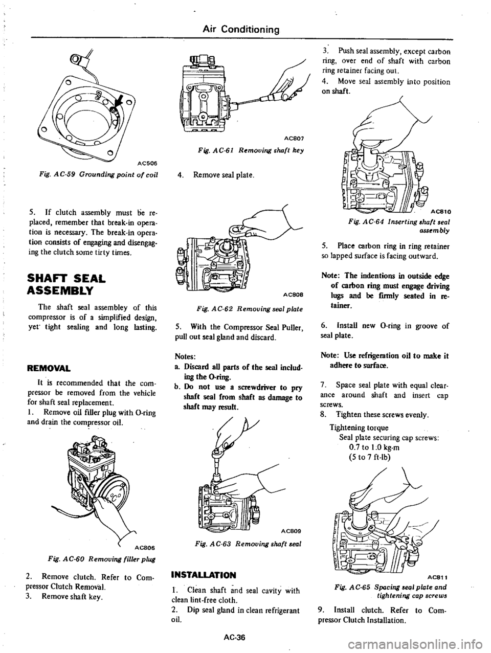
coil
for
shorted
or
opened
lead
wire
Pay
particular
attention
to
grounding
part
of
coil
If
there
is
no
continuity
replace
electromagnetic
coil
Page 525 of 537
AC506
Fig
AC
59
Grounding
point
of
coil
5
If
clutch
assembly
must
lie
re
placed
remember
that
break
in
opera
tion
is
necessary
The
break
in
opera
tion
consists
of
engaging
and
disengag
ing
the
clutch
some
tirty
times
SHAFT
SEAL
ASSEMBLY
The
shaft
seal
assembley
of
this
compressor
is
of
a
simplified
design
yet
tight
sealing
and
long
lasting
REMOVAL
It
is
recommended
that
the
com
pressor
be
removed
from
the
vehicle
for
shaft
seal
replacement
I
Remove
oil
filler
plug
with
D
ring
and
drain
the
compressor
oil
Fig
AC
60
Removing
filler
plug
2
Remove
clutch
Refer
to
Com
pressor
Clutch
Removal
3
Remove
shaft
key
Air
Conditioning
jpL
Y
L
I
i
0
I
I
0
Ace07
Fig
AC
61
Removing
s
wft
key
4
Remove
seal
plate
AC80e
Fig
AC
62
Removing
seal
plate
5
With
the
Compressor
Seal
Puller
pull
out
seal
gland
and
discard
Notes
a
Discard
all
parts
of
the
seal
includ
ing
the
O
ring
b
Do
not
use
a
screwdriver
to
pry
shaft
seal
from
shaft
as
damage
to
shaft
may
result
AC809
Fig
A
C
63
Removing
s
wft
eal
INSTALLATION
1
Clean
shaft
and
seal
cavity
with
clean
lint
free
cloth
2
Dip
seal
gland
in
clean
refrigerant
oil
AC
36
3
Push
seal
assembly
except
carbon
ring
over
end
of
shaft
with
carbon
ring
retainer
facing
out
4
Move
seal
assembly
into
position
on
shaft
1
I
Fig
AC
64
Inserting
wft
al
ass
mbly
5
Place
carbon
ring
in
ring
retainer
so
lapped
surface
is
facing
outward
Note
The
indentions
in
outside
edge
of
carbon
ring
must
engage
driving
lugs
and
be
firmly
seated
in
re
tainer
6
Install
new
D
ring
in
groove
of
seal
plate
Note
Use
refrigeration
oil
to
make
it
adhere
to
surface
7
Space
seal
plate
with
equal
clear
ance
around
shaft
and
insert
cap
screws
8
Tighten
these
screws
evenly
Tightening
torque
Seal
plate
securing
cap
screws
0
7
to
1
0
kg
m
5
to
7
ft
Ib
AC811
Fig
AC
65
8p
cing
01
plate
and
tightening
cap
screws
9
Install
clutch
Refer
to
Com
pressor
Clutch
Installation
Page 526 of 537

INSPECTION
Check
for
gas
leakage
as
follows
I
Plug
high
and
low
pressure
joints
on
compressor
with
blind
caps
2
Connect
charging
hoses
in
lines
between
manifold
gauge
and
high
and
low
pressure
service
valves
Connect
refrigerant
can
to
middle
hose
of
manifold
gauge
3
Open
valve
of
can
tap
and
charge
refrigerant
Loosen
oil
filler
plug
at
side
of
compressor
to
purge
air
out
of
compressor
4
Turn
shaft
5
or
6
turns
Then
confirm
that
pressure
does
not
decrease
on
low
pressure
gauge
If
gauge
indicates
a
pressure
decrease
there
is
a
leak
Conduct
a
leak
test
Under
such
a
condition
remove
and
then
install
parts
again
CYLINDER
HEAD
AND
VALVES
Insufficient
refrigerant
compression
is
likely
to
be
caused
by
damaged
head
gasket
or
damaged
valves
Prior
to
servicing
the
head
and
valve
plate
both
service
valves
should
be
opened
to
free
any
gas
pressure
which
may
be
in
the
compressor
REMOVAL
I
Remove
the
bolts
from
flanged
type
service
valves
using
Torx
Driver
Bit
Note
The
direction
of
flanged
type
service
valves
should
be
noted
for
reinstallation
AC812
Fig
AC
66
Removing
service
valves
2
Remove
the
remaining
bolts
in
the
head
Air
Conditioning
AC813
Fig
A
C
6
7
Removing
cylinder
head
bolts
3
Remove
valve
plate
and
head
from
cylinder
by
prying
or
tapping
under
the
ears
which
extend
from
valve
plate
If
head
and
valve
plate
adhere
hold
head
and
tap
valve
plate
ears
away
from
head
with
a
soft
hammer
Note
Do
not
hit
or
tap
head
to
separate
head
and
valve
plate
be
3use
damage
to
head
may
result
Fig
AC
68
Removing
valve
plate
and
head
4
When
removing
the
gaskets
use
a
sharp
edged
knife
Notes
a
In
removing
head
gasket
be
very
careful
not
to
damage
machined
sealing
surface
b
Do
not
reuse
gaskets
AC815
Fig
A
C
69
Removing
gasket
AC37
INSTALLATION
Valves
and
valve
plates
are
furnish
ed
only
as
a
complete
assembly
I
Apply
a
thin
film
of
clean
refrig
eration
oil
on
area
of
crankcase
to
be
covered
by
cylinder
gasket
2
Place
cylinder
gasket
in
position
on
cylinder
so
dowel
pins
in
crankcase
go
through
dowel
pin
holes
in
cylinder
gasket
3
Apply
a
thin
film
of
clean
refrig
eration
oil
to
top
and
bottom
valve
plate
areas
to
be
covered
by
gaskets
AC816
Fig
A
C
70
Applying
clean
refrigeration
oil
4
Place
valve
plate
in
position
on
cylinder
gasket
so
discharge
valve
as
semblies
i
e
smaller
diameter
assem
blies
with
restrainer
over
valve
reed
are
facing
up
and
locating
dowel
pins
go
through
dowel
pin
holes
in
valve
plate
Fig
A
C
71
Placing
valve
plate
Page 527 of 537

5
Place
head
gasket
in
position
on
valve
plate
so
dowel
pins
go
through
dowel
pin
holes
in
gasket
6
Apply
a
thin
film
of
clean
refrig
eration
oil
on
the
machined
surface
of
cylinder
head
which
matches
head
gasket
7
Place
head
on
cylinder
head
gasket
so
dowel
pins
go
into
dowel
pin
holes
in
head
Air
Conditioning
8
Apply
a
thin
fihn
of
clean
refrig
eration
oil
to
service
valve
flanges
9
Place
flange
valve
O
ring
in
posi
tion
on
cylinder
head
10
Place
service
valves
in
position
on
proper
service
valve
ports
suction
or
discharge
and
insert
two
longer
screws
through
service
valve
mountiing
pads
head
valve
plate
and
into
crank
AC
38
case
11
Insert
remammg
head
screws
and
run
in
all
screws
until
the
heads
make
contact
Tightening
torque
Head
and
service
valve
screws
2
1
to
3
2
kg
m
15
to
23
ft
lb
Page 528 of 537

Air
Conditioning
SPECIAL
SERVI
CE
TOOLS
Unit
mm
in
For
use
on
Reference
page
or
Figure
No
No
Tool
number
tool
name
Description
KV99100700
Clutch
wheel
remover
To
remove
clutch
wheel
from
V
pulley
620
Fig
AC
55
BE436
2
KV991006S0
To
install
clutch
wheel
into
V
pulley
620
Fig
AC
58
Clutch
wheel
38
1
50
1
installer
set
KV99100610
Installer
ST33061000
Stopper
BE437
3
ST33061000
To
remove
clutch
wheel
bearing
from
V
pulley
620
Fig
AC
56
Bearing
remover
38
1
50
BE438
4
ST02371000
To
install
clutch
wheel
bearing
into
V
pulley
620
Fig
AC
57
Bearing
installer
50
1
96
Co
tJ
BE439
AC
39
Page 529 of 537
Air
Conditioning
Tool
number
For
Reference
No
Description
use
page
or
Remarks
tool
name
Unit
mm
in
on
Figure
No
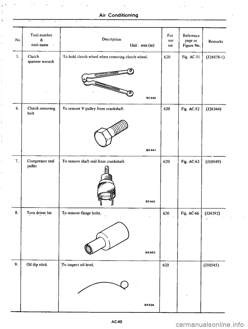
5
Clutch
To
hold
clutch
wheel
when
removing
clurch
wheel
620
Fig
AC
51
124878
1
spanner
wrench
6
Clutch
removing
bolt
7
Compressor
seal
puller
8
Torx
driver
bit
9
Oil
dip
stick
To
remove
V
pulley
from
crankshaft
To
remove
shaft
seal
from
crankshaft
To
remove
flange
bolts
To
inspect
oil
level
AC
40
BE440
BE441
BE442
B
E443
BE434
620
620
620
620
Fig
AC
52
126344
Fig
AC
63
J
10549
Fig
AC
66
124392
110545