heating DATSUN PICK-UP 1977 User Guide
[x] Cancel search | Manufacturer: DATSUN, Model Year: 1977, Model line: PICK-UP, Model: DATSUN PICK-UP 1977Pages: 537, PDF Size: 35.48 MB
Page 386 of 537
2
The
allowable
maximum
out
of
round
of
brake
drum
is
0
02
mm
0
0008
in
Re
condition
or
replace
brake
drum
if
specified
limit
is
exceeded
3
Measure
for
tapered
brake
drum
If
specified
limit
of
0
02
mm
0
0008
in
is
exceeded
as
measured
at
a
position
where
the
distance
of
4S
mm
177
in
is
kept
away
from
inlet
re
condition
or
replace
brake
drum
4
Contact
surface
with
which
linings
come
into
contact
should
be
finished
to
such
an
extent
that
it
is
ground
by
a
No
120
to
150
sand
paper
S
Using
a
drum
racer
finish
brake
drum
by
machining
if
it
shows
any
sign
of
score
marks
partial
wear
or
stepped
wear
on
its
contact
surface
Note
After
brake
drum
is
completely
re
conditioned
or
renewed
check
drum
and
shoes
for
proper
contact
pattern
Brake
assembly
I
When
brake
shoe
linings
are
cracked
incompletely
seated
uneven
Iy
worn
andlor
deteriorated
due
to
excessive
heating
or
soiled
with
oil
grease
and
brake
fluid
replace
2
Replace
linings
if
the
thickness
is
worn
down
to
less
than
1
0
mm
0
039
in
Note
When
brake
shoe
lining
is
in
stalled
grind
brake
shoe
lining
face
to
diameter
equal
to
that
of
brake
drum
lining
dimension
Width
x
Thickness
x
Length
4S
x
4
S
x
244
mm
1
77
x
0
177
x
9
61
in
3
Check
adjuster
for
smooth
oper
ation
4
Replace
shoe
return
springs
which
are
broken
or
fatigued
Brake
System
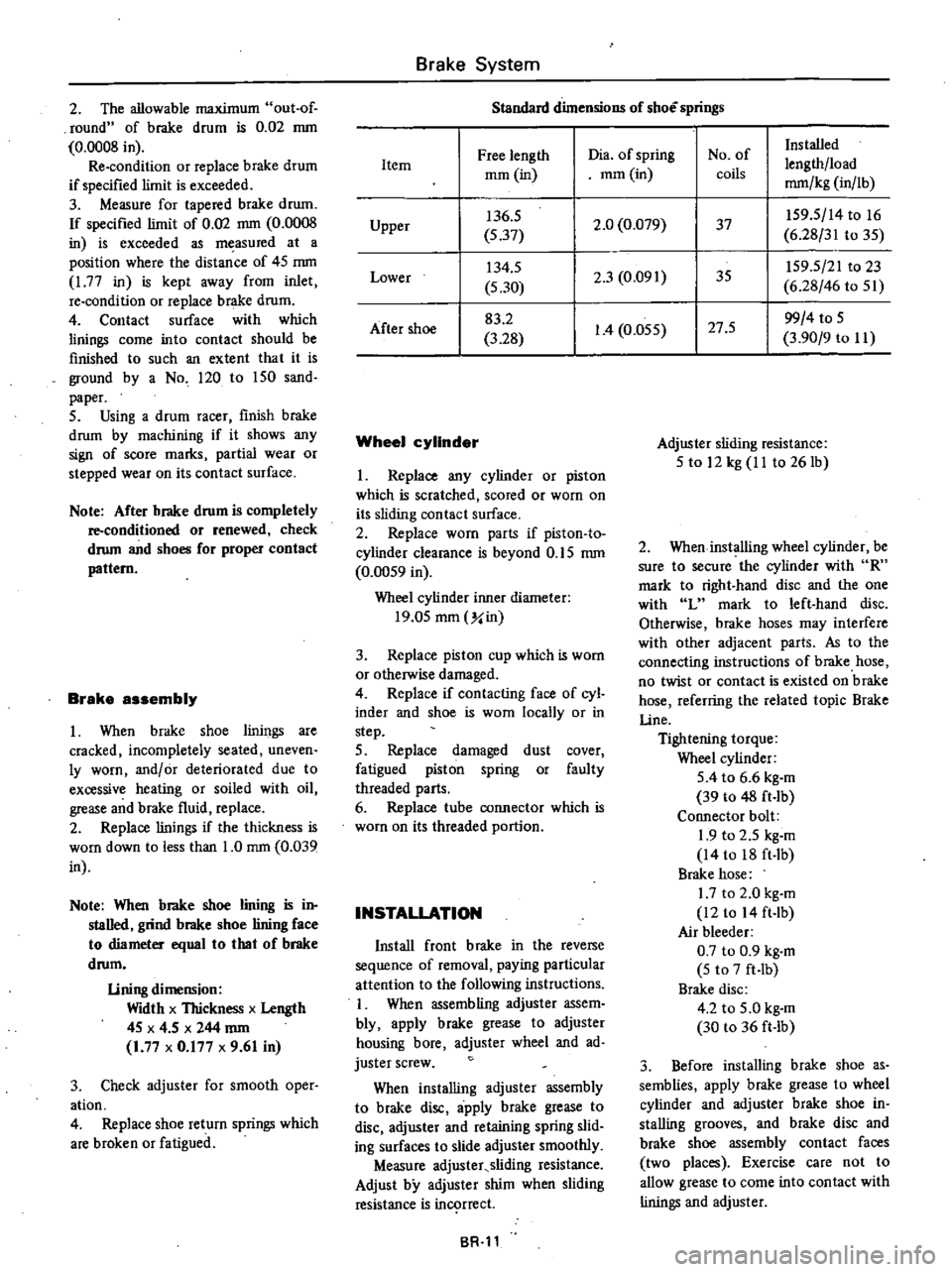
Standard
dimensions
of
shoe
springs
Free
length
Dia
of
spring
No
of
Installed
Item
lengthlload
mOl
in
mOl
in
coils
mm
kg
in
lb
Upper
136
5
2
0
0
079
37
IS9
S
14
to
16
S
37
6
28
31
to
3S
Lower
134
S
2
3
0
091
35
IS9
5
21
to
23
5
30
6
28
46
to
Sl
After
shoe
83
2
1
4
O
OSS
27
S
99
4
to
S
3
28
3
90
9
to
II
Wheel
cylinder
I
Replace
any
cylinder
or
piston
which
is
scratched
scored
or
worn
on
its
sliding
contact
surface
2
Replace
worn
parts
if
piston
to
cylinder
clearance
is
beyond
O
IS
mm
0
OOS9
in
Wheel
cylinder
inner
diameter
19
0S
mOl
Y
in
3
Replace
piston
cup
which
is
worn
or
otherwise
damaged
4
Replace
if
contacting
face
of
cyl
inder
and
shoe
is
worn
locally
or
in
step
S
Replace
damaged
dust
cover
fatigued
piston
spring
or
faulty
threaded
parts
6
Replace
tube
connector
which
is
worn
on
its
threaded
portion
INSTALLATION
Install
front
brake
in
the
reverse
sequence
of
removal
paying
particular
attention
to
the
following
instructions
I
When
assembling
adjuster
assem
bly
apply
brake
grease
to
adjuster
housing
bore
adjuster
wheel
and
ad
juster
screw
When
installing
adjuster
assembly
to
brake
disc
apply
brake
grease
to
disc
adjuster
and
retaining
spring
slid
ing
surfaces
to
slide
adjuster
smoothly
Measure
adjuster
sliding
resistance
Adjust
by
adjuster
shim
when
sliding
resistance
is
in
rrect
BR
ll
Adjuster
sliding
resistance
S
to
12
kg
II
to
261b
2
When
installing
wheel
cylinder
be
sure
to
secure
the
cylinder
with
R
mark
to
right
hand
disc
and
the
one
with
L
mark
to
left
hand
disc
Otherwise
brake
hoses
may
interfere
with
other
adjacent
parts
As
to
the
connecting
instructions
of
brake
hose
no
twist
or
contact
is
existed
on
brake
hose
referring
the
related
topic
Brake
line
Tightening
torque
Wheel
cylinder
SA
to
6
6
kg
m
39
to
48
ft
lb
Connector
bolt
1
9
to
2
5
kg
m
14
to
18
ft
Ib
Brake
hose
1
7
to
2
0
kg
m
12
to
14
ft
lb
Air
bleeder
0
7
to
0
9
kg
m
5
to
7
ft
Ib
Brake
disc
4
2
to
S
O
kg
m
30
to
36
ft
lb
3
Before
installing
brake
shoe
as
semblies
apply
brake
grease
to
wheel
cylinder
and
adjuster
brake
shoe
in
stalling
grooves
and
brake
disc
and
brake
shoe
assembly
contact
faces
two
places
Exercise
care
not
to
allow
grease
to
come
into
contact
with
linings
and
adjuster
Page 388 of 537
DISASSEMBLY
AND
ASSEMBLY
Wheel
cylinder
Remove
dust
cover
and
pull
out
piston
head
and
piston
assembly
Refer
to
Wheel
Cylinder
of
Front
Brake
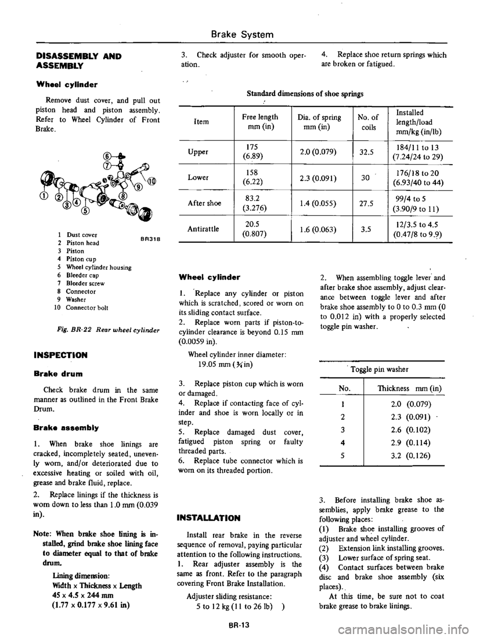
CD
l
ID
345
0
1
Dust
cover
2
Piston
head
3
Piston
4
Piston
Cll
p
5
Wheel
cylinder
housing
6
Bleeder
cap
7
Bleeder
screw
8
Connector
9
Washer
10
Connector
bolt
BR318
Fig
BR
22
Rear
wheel
cylinder
INSPECTION
Brake
drum
Check
brake
drum
in
the
same
manner
as
outlined
in
the
Front
Brake
Drum
Brake
assembly
I
When
brake
shoe
linings
are
cracked
incompletely
seated
uneven
ly
worn
andlor
deteriorated
due
to
excessive
heating
or
soiled
with
oil
grease
and
brake
fluid
replace
2
Replace
linings
if
the
thickness
is
WOol
down
to
less
than
1
0
rom
0
039
in
Note
When
brake
shoe
lining
is
in
stalled
grind
brake
shoe
lining
face
to
diameter
equal
10
lha
I
of
brake
drom
Lining
dimemion
Width
x
Thickness
x
Length
4S
x
4
5
x
244
rom
1
77
x
0
177
x
9
61
in
Brake
System
3
Check
adjuster
for
smooth
oper
ation
4
Replace
shoe
return
springs
which
are
broken
or
fatigued
Standard
dimensions
of
shoe
springs
Dia
of
spring
No
of
Installed
Free
length
lengthlload
Item
mOl
in
mOl
in
coils
mmlkg
in
lb
175
2
0
0
079
32
5
184
11
to
13
Upper
6
89
7
24
24
to
29
158
2
3
0
091
30
176
18
to
20
Lower
6
22
6
93
40
to
44
83
2
1
4
0
055
27
5
99
4
to
S
After
shoe
3
276
3
90
9
to
II
20
5
1
6
0
063
3
5
12
3
S
to
4
5
AntiratUe
0
807
0
47
8
to
9
9
Wheel
cylinder
I
Replace
any
cylinder
or
piston
which
is
scratched
scored
or
worn
on
its
sliding
contact
surface
2
Replace
worn
parts
if
piston
to
cylinder
clearance
is
beyond
O
IS
rom
0
00S9
in
Wheel
cylinder
inner
diameter
19
0S
rom
Xin
3
Replace
piston
cup
which
is
worn
or
damaged
4
Replace
if
contacting
face
of
cyl
inder
and
shoe
is
worn
locally
or
in
step
5
Replace
damaged
dust
cover
fatigued
piston
spring
or
faulty
threaded
parts
6
Replace
tube
connector
which
is
worn
on
its
threaded
portion
INSTALLATION
Install
rear
brake
in
the
reverse
sequence
of
removal
paying
particular
attention
to
the
following
instructions
I
Rear
adjuster
assembly
is
the
same
as
front
Refer
to
the
paragraph
covering
Front
Brake
Installation
Adjuster
sliding
resistance
S
to
12
kg
II
to
261b
BR
13
2
When
assembling
toggle
lever
and
after
brake
shoe
assembly
adjust
clear
ance
between
toggle
lever
and
after
brake
shoe
assembly
to
0
to
0
3
mOl
0
to
0
012
in
with
a
properly
selected
toggle
pin
washer
Toggle
pin
washer
No
Thickness
rom
in
I
2
0
0
079
2
2
3
0
091
3
2
6
0
102
4
2
9
0
114
S
3
2
0
126
3
Before
installing
brake
shoe
as
semblies
apply
brake
grease
to
the
following
places
1
Brake
shoe
installing
grooves
of
adjuster
and
wheel
cylinder
2
Extension
link
installing
grooves
3
Lower
surface
of
spring
seat
4
Contact
surfaces
between
brake
disc
and
brake
shoe
assembly
six
places
At
this
time
be
sure
not
to
coat
brake
grease
to
brake
linings
Page 447 of 537
DESCRIPTION
Cables
are
covered
with
color
coded
vinyl
for
easy
identification
In
the
wiring
diagram
colors
are
indicated
by
one
or
two
alphabetical
letters
It
is
recommended
that
the
battery
be
disconnected
before
performing
any
electrical
service
other
than
bulb
or
fuse
replacement
In
addition
to
fuses
a
fusible
link
has
been
installed
to
protect
wiring
The
fusible
link
functions
almost
the
same
as
a
fuse
though
its
eharac
teristics
are
slightly
different
than
normal
fuses
CABLE
COLORS
Cable
colors
are
indicated
by
one
or
two
alphabetical
letters
B
Black
Be
Brown
G
Green
L
Blue
Lg
Light
green
R
Red
W
White
Y
Yellow
The
main
cable
is
generally
coded
with
a
single
color
The
others
are
coded
with
a
two
tone
color
as
follows
BW
Black
with
white
stripe
gR
Light
green
with
red
stripe
INSPECTION
Inspect
all
electrical
circuits
refer
ring
to
wiring
or
circuit
diagrams
Circuits
should
be
tested
for
conti
nuity
or
short
circuit
with
a
conven
tional
test
lamp
or
low
reading
volt
meter
Before
inspection
of
circuit
ensure
that
I
Each
electrical
component
part
or
cable
is
securely
fastened
to
its
con
nector
or
terminal
2
Each
connection
is
firmly
in
place
and
free
from
rust
and
dirt
3
No
cable
covering
shows
any
evidence
of
cracks
deterioration
or
other
damage
4
Each
terminal
is
at
a
safe
distance
away
from
any
adjacent
metal
parts
5
Each
cable
is
fastened
to
its
proper
connector
or
terminal
Body
Electrical
System
BODY
ELECTRICAL
WIRING
6
Each
grounding
bolt
is
firmly
pbnted
7
Wiring
is
kept
away
from
any
adjacent
parts
with
sharp
edges
or
high
temperature
parts
such
as
exhaust
pipe
8
Wiring
is
kept
away
from
any
rotating
or
working
parts
fan
pulley
fan
belt
etc
9
Cables
between
ftxed
portions
and
moving
parts
are
long
enough
to
withstand
shocks
and
vibratory
forces
Notes
a
Before
starting
to
inspect
and
repair
any
part
of
electrical
system
or
other
parts
which
may
lead
to
a
short
circuit
disconnect
cables
at
battery
terminals
as
follows
Disconnect
cable
at
negative
terminal
and
then
disconnect
cable
at
positive
terminal
Before
connecting
cables
to
battery
terminal
be
sure
to
clean
terminals
with
a
rag
Fasten
cable
at
positive
terminal
and
then
ground
cable
at
negative
terminal
Apply
grease
to
top
of
these
terminals
to
prevent
rust
from
developing
on
them
b
Never
use
a
screwdriver
or
senrice
tool
to
conduct
a
continuity
test
Use
test
leads
c
Never
ground
an
open
circuit
or
circuits
under
no
load
Use
a
test
lamp
12V
3W
or
circuit
tester
as
a
load
FUSE
AND
FUSIBLE
LINK
DESCRIPTION
The
fuse
and
fusible
link
are
protec
tive
devices
used
in
an
electrical
cir
cuit
When
current
increases
beyond
rated
amperage
fusible
metal
melts
and
the
circuit
is
broken
BE
2
MAINTENANCE
INSTRUCTIONS
Fuse
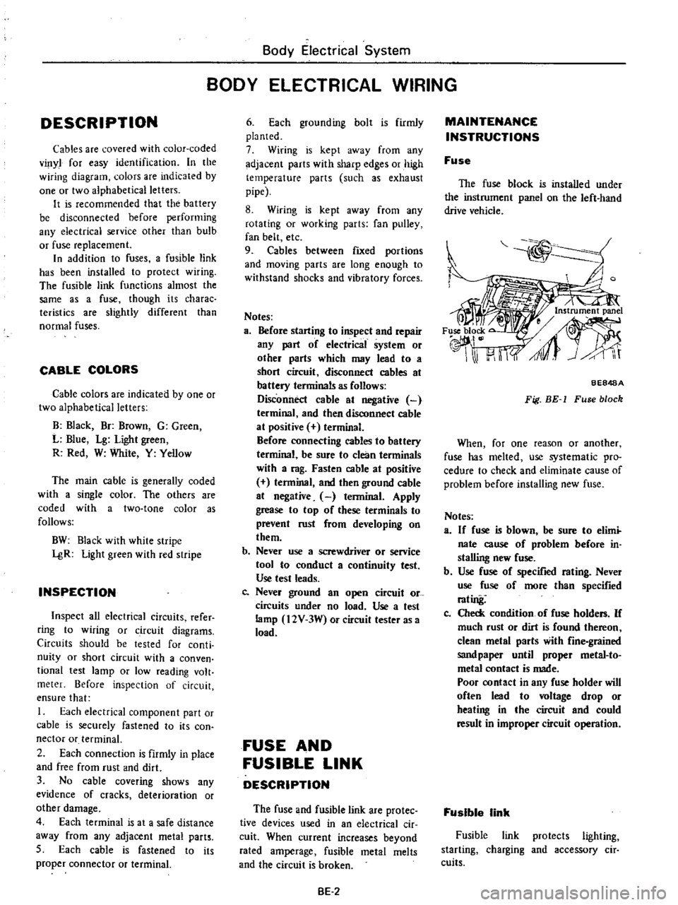
The
fuse
block
is
installed
under
the
instrument
panel
on
the
left
hand
drive
vehicle
BE848A
Fig
BE
1
Fuse
block
When
for
one
reason
or
another
fuse
has
melted
use
systematic
pro
cedure
to
check
and
eliminate
cause
of
problem
before
installing
new
fuse
Notes
a
If
fuse
is
blown
be
sure
to
elimi
nate
cause
of
problem
before
in
stalling
new
fuse
b
Use
fuse
of
specified
rating
Never
use
fuse
of
more
than
specified
rating
Co
Check
condition
of
fuse
holders
If
much
rust
or
dirt
is
found
thereon
clean
metal
parts
with
fine
grained
sandpaper
until
proper
metal
to
metal
contact
is
made
Poor
contact
in
any
fuse
holder
will
often
lead
to
voltage
drop
or
heating
in
the
circuit
and
could
result
in
improper
circuit
operation
Fusible
link
Fusible
link
protects
lighting
starting
charging
and
accessory
cir
cuits
Page 473 of 537

Body
Electrical
System
AIRFLOW
OFF
VENTILATING
Push
Vent
valve
Heater
core
c
n
e
NlL
fAl
u
c
J
u
IUl
g
Push
Pull
DEFROSTING
VENTILATING
HEATING
0
tTIlsl
IU
lI
D
WI
Push
Pull
g
IIt
J
L
I
I
Pull
Pull
DEFROSTING
HEATING
n
C
IU
n
HU
I
ff
UIUI
C
J
CIl
JIlT
Ill
Pull
J
11
Pull
BE397
Fig
BE
47
Airflow
8E
28
Page 502 of 537
J
I
1
Air
Conditioning
J
lJ
R
J
g
j
ru
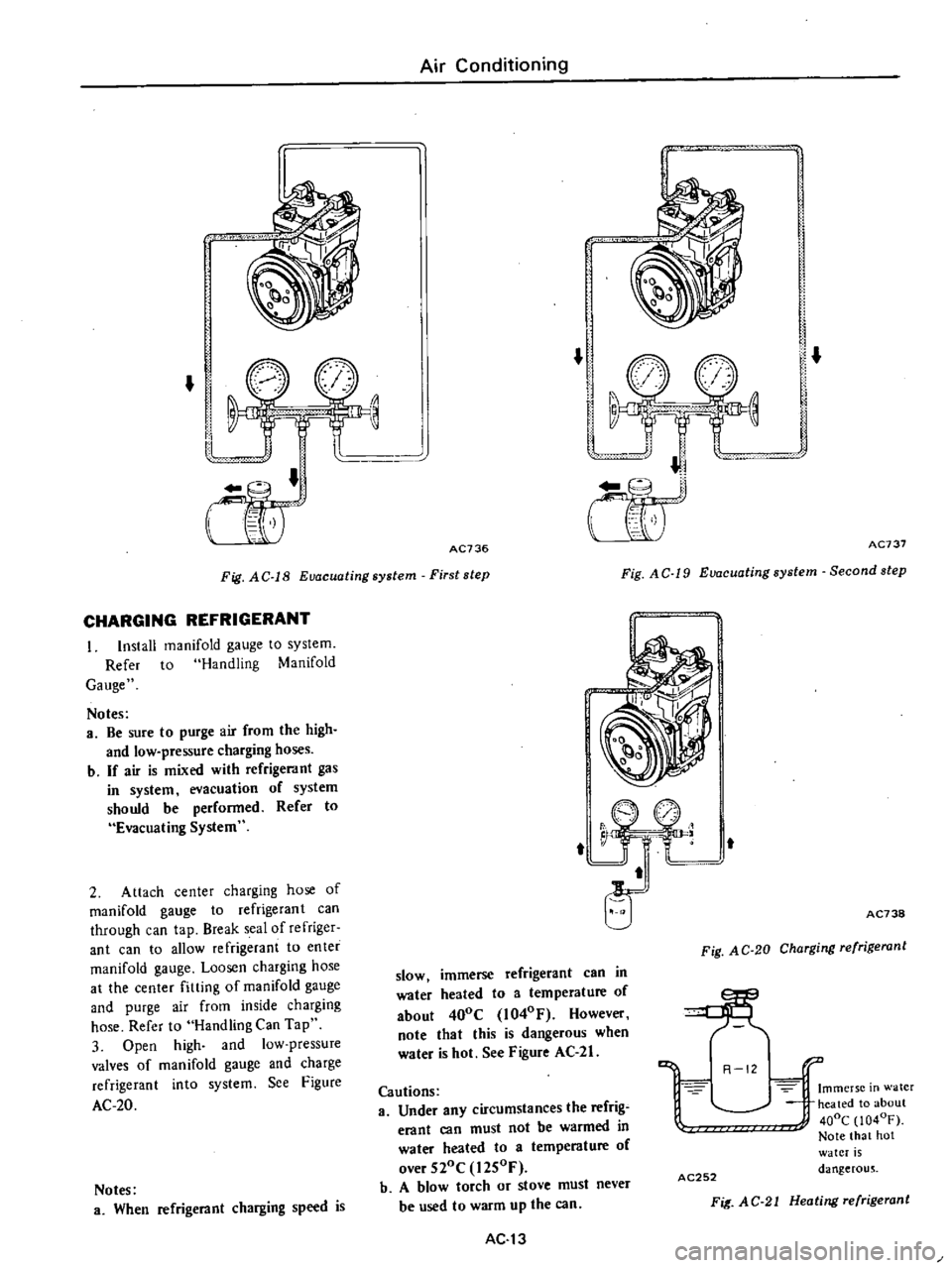
Fig
A
C
l8
Euacuating
system
First
step
AC736
Fig
AC
19
Euacuatingsystem
Second
step
AC737
CHARGING
REFRIGERANT
I
Install
manifold
gauge
to
system
Refer
to
Handling
Manifold
Gauge
Notes
a
Be
sure
to
purge
air
from
the
high
and
low
pressure
charging
hoses
b
If
air
is
mixed
with
refrigerant
gas
in
system
evacuation
of
system
should
be
performed
Refer
to
Evacuating
System
2
Attach
center
charging
hose
of
manifold
gauge
to
refrigerant
can
through
can
tap
Break
seal
of
refriger
ant
can
to
allow
refrigerant
to
enter
manifold
gauge
Loosen
charging
hose
at
the
center
fitting
of
manifold
gauge
and
purge
air
from
inside
charging
hose
Refer
to
Handling
Can
Tap
3
Open
high
and
low
pressure
valves
of
manifold
gauge
and
charge
refrigerant
into
system
See
Figure
AC
20
Notes
a
When
refrigerant
charging
speed
is
1
j
jJ
i
j
Fig
AC
20
Charging
refrigerant
AC738
slow
immerse
refrigerant
can
in
water
heated
to
a
temperature
of
about
400C
l040F
However
note
that
this
is
dangerous
when
water
is
hot
See
Figure
AC
21
Cautions
a
Under
any
circumstances
the
refrig
erant
can
must
not
be
warmed
in
water
heated
to
a
temperature
of
over
520C
l2S0F
b
A
blow
torch
or
stove
must
never
be
used
to
warm
up
the
can
R
121
Immerse
in
water
heated
to
about
400C
1040F
Note
that
hot
water
is
dangerous
AC252
Fit
AC
21
Heating
refrigerant
AC13
Page 510 of 537
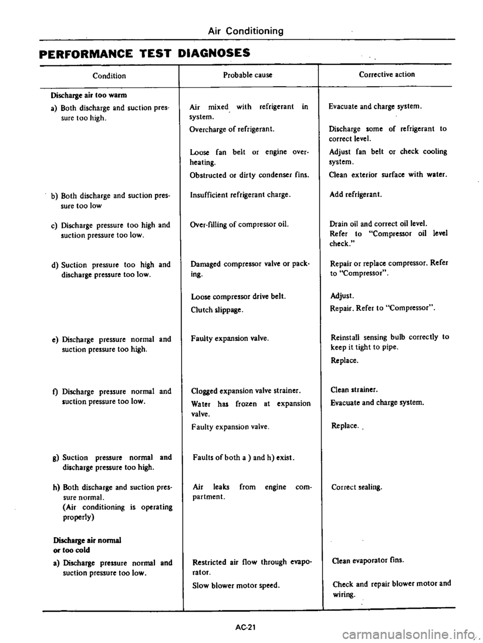
Air
Conditioning
PERFORMANCE
TEST
DIAGNOSES
Condition
Discharge
air
too
warm
a
Both
discharge
and
suction
pres
sure
too
high
b
Both
discharge
and
suction
pres
sure
too
low
c
Discharge
pressure
too
high
and
suction
pressure
too
low
d
Suction
pressure
too
high
and
discharge
pressure
too
low
e
Discharge
pressure
normal
and
suction
pressure
too
high
t
Discharge
pressure
normal
and
luction
pressure
too
low
g
Suction
pressure
normal
and
discharge
pressure
too
high
h
Both
discharge
and
suction
pres
sure
normal
Air
conditioning
is
operating
properly
Discharge
air
normal
or
too
cold
a
Discharge
pressure
normal
and
suction
pressure
too
low
Probable
cause
Air
mixed
with
refrigerant
in
system
Overcharge
of
refrigerant
Loose
fan
belt
or
engine
over
heating
Obstructed
or
dirty
condenser
fins
Insufficient
refrigerant
charge
Over
filling
of
compressor
oil
Damaged
compressor
valve
or
pack
ing
Loose
compressor
drive
belt
Clutch
slippage
Faulty
expansion
valve
Clogged
expansion
valve
strainer
Water
has
frozen
at
expansion
valve
Faulty
expansion
valve
Faults
of
both
a
and
h
exist
Air
leaks
from
engine
com
partment
Restricted
air
flow
through
evapo
ratof
Slow
blower
motor
speed
AC
21
Corrective
action
Evacuate
and
charge
system
Discharge
some
of
refrigerant
to
correct
level
Adjust
fan
belt
or
check
cooling
system
Clean
exterior
surface
with
water
Add
refrigerant
Drain
oil
and
correct
oil
level
Refer
to
Compressor
oil
level
check
Repair
or
replace
compressor
Refer
to
Compressor
Adjust
Repair
Refer
to
Compressor
Reinstall
sensing
bulb
correctly
to
keep
it
tight
to
pipe
Replace
Clean
strainer
Evacuate
and
charge
system
Replace
Correct
sealing
Clean
evaporator
fins
Check
and
repair
blower
motor
and
wiring