maintenance DATSUN PICK-UP 1977 Service Manual
[x] Cancel search | Manufacturer: DATSUN, Model Year: 1977, Model line: PICK-UP, Model: DATSUN PICK-UP 1977Pages: 537, PDF Size: 35.48 MB
Page 3 of 537
FOREWORD
This
service
manual
has
been
prepared
for
the
purpose
of
assisting
service
personnel
of
authorized
NISSAN
DATSUN
dealers
fu
providing
effective
service
and
maintenance
of
the
1977
Datsun
Pick
up
Since
proper
maintenance
and
service
are
absolutely
essential
fu
satisfying
the
Datsun
owners
this
inan
la1
should
be
kept
fu
a
handy
place
for
ready
reference
and
should
be
carefuny
studied
This
man
la1
fucludes
procedures
for
ma
futenance
ac
1justrnents
minor
service
operations
remowl
and
installation
and
for
disassembly
and
assembly
of
components
Some
of
these
service
operations
require
the
use
of
Special
Tools
especially
designed
for
effectiveperfonnance
of
service
operations
The
special
tools
are
presented
in
the
SE
section
As
you
read
through
the
maintenance
procedures
in
this
service
manual
you
will
occasionally
corne
across
paragraphs
headed
NOTE
or
CAUTION
A
NOTE
is
supplemental
infortl1ation
that
is
important
to
B
particular
procedure
CAUTION
warns
of
steps
that
must
be
fonowed
to
prevent
personal
injury
and
Qr
damage
to
some
part
of
your
DATSUN
The
Quick
Reference
Index
on
the
first
page
enables
the
user
to
quickly
locate
the
desired
section
At
the
beginning
of
each
individual
section
is
a
table
of
contents
which
gives
the
page
number
on
which
each
major
subject
begins
An
index
is
placed
at
the
beginning
of
each
major
subject
within
the
section
All
information
illustrations
and
specifications
contained
in
this
manual
are
based
on
the
latest
product
information
available
at
the
time
of
publication
approval
If
YOUT
DATSUN
model
differs
from
the
specifications
contained
in
this
manual
consult
your
NlSSAN
DATSUN
dealer
for
information
Rights
for
alteratiohat
any
time
of
specifications
and
methods
are
reserved
liability
for
any
personal
injury
or
property
damage
occasioned
by
the
use
of
this
service
man
la1
in
effecting
maintenance
or
repair
of
your
Datsun
is
in
no
way
assumed
by
Nissan
M9tor
Co
Ltd
Accordingly
anyone
using
a
service
procedure
or
tool
which
is
not
specifically
w
mended
by
Nissan
must
fust
completely
satisfy
himself
that
neither
his
safety
nor
the
vehicle
s
safety
wi11be
jeopardized
by
the
service
method
selected
NISSAN
MOTOR
CO
LTD
TOKYO
JAPAN
@
1976
N1SSAN
MOTOR
CO
LTD
Printed
in
Japan
Page 18 of 537
EMISSION
CONTROL
DEVICES
Enj
Jn
illUde
I
I
AI4
I
L20H
I
11210
FlU
620
NOll
Califor
Non
aUfon
C
hfor
C
lifomla
lIIodch
EJ
L
lPI
Canada
models
Cilnada
CalifornIa
Non
CaliflJl
model
forC
anada
models
Except
modcb
rllodet
Canada
I
M
T
I
AlT
I
M
T
I
AlT
I
M
T
I
A
T
M
T
M
T
I
AfT
M
T
I
AfT
I
A
T
C
Jtrc1cancr
wllh
l1r
numn
rclirfvalvc
I
I
I
X
I
X
I
X
I
X
I
X
I
X
I
I
1
X
I
I
A
T
e
lliT
dl
1er
wilh
l
4t
air
llUlilprCn
rv
I
wflh
tlitlji
Jc
m1JC
ill
i
l
I
I
I
X
I
I
I
I
I
I
AIR
CLEANER
I
A
T
e
air
deaner
with
air
PUlnt
relicI
valve
wilh
iltitudc
compcn
alor
valvel
1
I
I
I
X
I
X
I
I
I
hlle
comDenlator
duallvQe
X
X
X
I
X
I
X
X
X
X
X
I
X
X
I
X
I
X
F
lh
air
due
fo
introducinil
ullidc
air
I
X
I
X
I
X
I
X
I
X
I
X
X
I
X
I
X
I
X
1
X
I
X
I
X
ENGINE
I
Early
fuclcvuporatlYe
sYltem
exhaust
hcalm
I
X
I
X
I
X
I
X
I
X
I
X
X
I
I
X
I
X
I
X
I
X
X
PROPER
X
P
T
C
auluchnkc
I
I
X
1
X
I
X
I
X
X
X
I
X
X
X
I
X
X
X
I
a
c
OO
with
l
onlrol
lIve
I
I
I
I
I
I
I
X
X
CARBURETOR
I
8
C
D
0
without
control
valve
control
valve
attached
to
body
I
I
I
I
X
I
X
m
Throltle
o
ncr
with
control
val
l
X
X
X
X
X
X
X
l
Onlhoot
I
X
I
X
I
X
I
X
I
X
X
X
I
X
I
X
X
I
X
I
X
X
c
I
Altitude
c
Jmpcmalor
with
pipe
fo
U
IC
in
air
bleed
I
X
I
X
I
I
I
I
X
I
X
I
X
0n
tranmlor
unIt
Oiltribulor
II
olck
UD
I
X
I
X
I
I
I
I
X
I
I
X
I
X
I
IGNITION
T
C
S
ISwilchin
valve
I
m
d
llI11OfCuioll
C
l
1J1
TO
l
X
X
X
X
I
X
X
X
I
j
x
SYSTEM
I
S
D
V
Sn
arkdelayvalvc
I
I
I
X
I
I
I
I
I
T
V
V
Thermal
vlcuum
a
vc
r
c
s
I
X
I
X
I
X
I
X
I
X
I
X
X
X
I
X
I
I
I
I
Air
pump
AlP
all
cleaner
Ched
valve
A
B
vlllvc
I
X
X
I
X
I
X
I
X
I
X
X
X
I
X
X
I
X
X
I
X
1
C
A
t
valve
fAir
eonlrol
valve
E
A
R
valve
Rcliefvalvel
X
X
I
X
I
A
I
S
I
Airconlrot
valve
I
I
I
I
X
I
X
I
E
A
R
valve
I
I
I
I
X
I
X
I
Rcliervalvc
I
I
X
I
X
I
X
I
X
X
I
X
I
X
I
X
X
I
X
r
E
G
R
VUIVllID
P
T
svstem
I
X
X
I
X
I
X
I
I
X
X
E
G
R
LG
R
v
lvr
Ive
sv
tem
I
I
X
I
X
I
I
X
X
I
X
X
I
X
SYSTEM
fThermal
acuum
valve
E
C
R
X
X
I
X
I
X
I
X
X
X
X
I
X
I
X
I
X
X
I
X
T
C
J
ITon
cut
E
G
R
I
I
I
X
I
I
I
X
I
I
Wamin
device
e
l
ry
12
500
mile
maintenance
I
I
I
I
I
I
I
I
I
X
I
X
CATALYZER
e
lalvIIC
ln
rler
X
X
I
I
I
I
X
I
I
I
X
I
X
Fluor
h
mocrature
waminl
5Vllcm
with
noor
ICnlor
I
X
X
I
I
I
I
X
I
I
I
X
I
X
Newly
equipped
unit
1917
models
Remark
X
Available
Not
available
M
T
AlT
A
T
C
PT
Ch
T
V
V
C
A
C
Maouallrammln
Automallctunsmls
Automatic
temperature
control
Positive
temperature
cod
icll
nt
Thermal
vacuum
valve
Combined
oLir
control
8
C
0
D
T
C
S
S
D
V
T
C
E
B
P
T
V
c
Boolt
controlled
deceleration
dov
Tran
mlu
controlled
vacuum
advam
system
Spark
delay
valve
TransmlSl
ulI
controlled
exhausl
gu
recnculltlOn
1
lIem
Back
preuure
nansduce
Vacuum
AJ
S
A
B
vlllve
E
A
R
V
Jlvc
E
C
R
V
O
V
T
C
E
AHmjcL
Anu
b
H
ktiu
alvc
Emer
cncy
relief
alvc
E
dlllu
ll
r
r
ula
Vacuum
dclay
11Ie
Tup
E
G
R
E
l
l
epl
t
orCanuda
lIIIII
m
J
C
r
l
l
c
J
l
c
0
Page 27 of 537
Engine
Tune
up
EC284
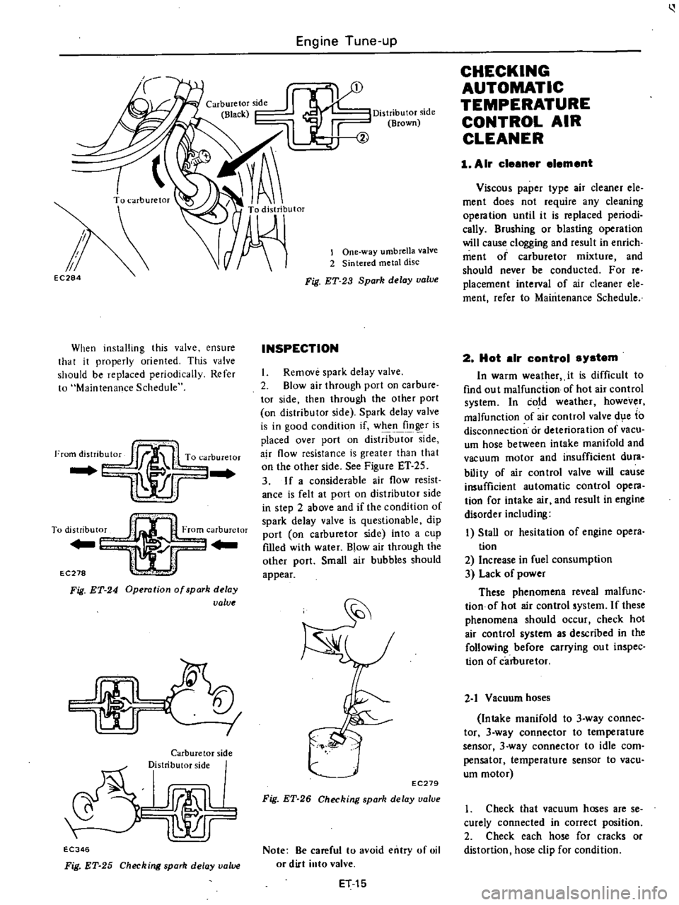
When
installing
this
valve
ensure
that
it
properly
oriented
This
valve
should
be
replaced
periodically
Refer
to
Maintenance
Schedule
I
To
distribut0
From
carburetor
Yl
r
EC278
l
Fig
ET
24
Operation
of
spark
delay
value
I
I
Carburetor
side
Distributor
side
rJmlL
lr
EC346
Fig
ET
25
Checking
spark
delay
value
Distributor
side
Brown
lOne
way
umbrella
valve
2
Sintered
metal
disc
Fig
ET
23
Spark
delay
valve
INSPECTION
I
Remove
spark
delay
valve
2
Blow
air
through
port
on
carbure
tor
side
then
through
the
other
port
on
distributor
side
Spark
delay
valve
is
in
good
condition
if
when
finger
is
placed
over
port
on
distrib
side
ajr
flow
resistance
is
greater
than
that
on
the
other
side
See
Figure
ET
25
3
If
a
considerable
air
flow
resist
ance
is
felt
at
port
on
distributor
side
in
step
2
above
and
if
the
condition
of
spark
delay
valve
is
questionable
dip
port
on
carburetor
side
into
a
cup
fIlled
with
water
Blow
air
through
the
other
port
Small
air
bubbles
should
appear
EC279
Fig
ET
26
Checking
spark
delay
ualue
Note
Be
careful
to
avoid
entry
of
oil
or
dirt
into
valve
ET
15
CHECKING
AUTOMATIC
TEMPERATURE
CONTROL
AIR
CLEANER
1
Air
cleener
element
Viscous
paper
type
air
cleaner
ele
ment
does
not
require
any
cleaning
opera
tion
until
it
is
replaced
periodi
cally
Brushing
or
blasting
operation
will
cause
clogging
and
result
in
enrich
ment
of
carburetor
mixture
and
should
never
be
conducted
For
reo
placement
interval
of
air
cleaner
ele
ment
refer
to
Maintenance
Schedule
2
Hot
elr
control
system
In
warm
wealher
it
is
difficult
to
find
ou
t
malfunction
of
hot
air
control
system
In
cold
weather
however
malfunction
of
air
control
valve
d
e
to
disconnection
or
deterioration
of
vacu
um
hose
between
intake
manifold
and
vacuum
motor
and
insufficient
dura
bili
ty
of
air
con
trol
valve
will
cause
insufficient
automatic
control
opera
tion
for
intake
air
and
result
in
engine
disorder
including
I
Stall
or
hesitation
of
engine
opera
tion
2
Increase
in
fuel
consumption
3
Lack
of
power
These
phenomena
reveal
malfunc
tionof
hot
air
control
system
If
these
phenomena
should
occur
check
hot
air
control
system
as
described
in
the
following
before
carrying
ou
t
inspec
tion
of
carburetor
2
1
Vacuum
hoses
Intake
manifold
to
3
way
connec
tor
3
way
connector
to
temperature
sensor
3
way
connector
to
idle
com
pensator
temperature
sensor
to
vacu
um
motor
1
Check
that
vacuum
hoses
are
se
curely
connected
in
correct
position
2
Check
each
hose
for
cracks
or
distortion
hose
clip
for
condition
Page 102 of 537
r
AIR
CLEANER
1
Loosen
bolts
securing
air
cleaner
to
air
cleaner
bracket
2
Loosen
air
cleaner
lock
bolt
and
remove
air
cleaner
from
carburetor
Disconnect
the
following
hoses
when
dismounting
air
cleaner
Under
hood
air
inlet
hose
Hot
air
inlet
hose
Vacuum
hose
Sensor
to
intake
manifold
Vacuum
hose
Sensor
to
vacuum
motor
Vacuum
hose
Idle
compensator
to
intake
manifold
Hose
Air
pump
to
air
cleaner
Hose
AB
valve
to
air
cleaner
Hose
Carburetor
to
air
cleaner
Blow
by
hose
Air
cleaner
to
rocker
cover
Hose
Air
control
vaive
to
air
cleaner
California
models
only
3
To
install
reverse
the
removal
procedure
INSPECTION
1
AIR
CLEANER
ELEMENT
Viscous
paper
type
air
cleaner
ele
ment
does
not
require
any
cleaning
operation
until
it
is
replaced
periodi
cally
Brushing
or
blasting
operation
will
cause
clogging
and
result
in
enrich
ment
of
carburetor
mixture
and
should
never
be
conducted
For
reo
placement
interval
of
air
cleaner
ele
ment
refer
to
Maintenance
Sched
ule
2
HOT
AIR
CONTROL
SYSTEM
In
warm
weather
it
is
difficult
to
find
out
malfunction
of
hot
air
control
system
In
cold
wea
thee
however
malfunction
of
air
control
valve
due
to
disconnection
or
deterioration
of
vacu
um
hose
between
intake
manifold
and
vacuum
motor
and
insufficient
dura
bility
of
air
control
valve
will
cause
insufficient
automatic
control
opera
tion
for
intake
air
and
result
in
engine
disorder
including
I
Stall
or
hesitation
of
engine
oper
ation
2
Increase
in
fuel
consumption
3
uck
of
power
Engine
Fuel
These
phenomena
reveal
malfunc
tion
of
hot
air
control
system
If
these
phenomena
should
occur
check
hot
air
control
system
as
described
in
the
following
before
carrying
out
inspec
tion
of
carburetor
2
1
Vacuum
hose
Intake
manifold
to
3
way
connec
tor
3
way
connector
to
temperature
sensor
3
way
connector
to
idle
com
pensator
temperature
sensor
to
vacu
um
motor
I
Check
that
vacuum
hoses
are
se
curely
connected
in
correct
postion
2
Check
each
hose
for
cracks
or
distortion
hose
clip
for
condition
Note
Vacuum
hose
position
R
H
side
of
Nissan
mark
on
the
top
of
sensor
is
for
intake
manifold
L
U
side
of
the
mark
is
for
vacuum
motor
2
2
Vacuum
motor
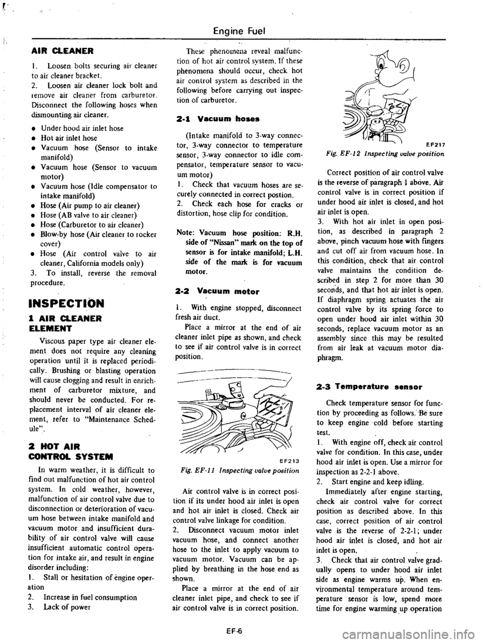
I
With
engine
stopped
disconnect
fresh
air
duct
Place
a
mirror
at
the
end
of
air
cleaner
inlet
pipe
as
shown
and
check
to
see
if
air
con
trol
valve
is
in
correct
position
EF213
Fig
EF
11
Inspecting
valve
position
Air
control
valve
is
in
correct
posi
tion
if
its
under
hood
air
inlet
is
open
and
hot
air
inlet
is
closed
Check
air
control
valve
linkage
for
condition
2
Disconnect
vacuum
motor
inlet
vacuum
hose
and
connect
another
hose
to
the
inlet
to
apply
vacuum
to
vacuum
motor
Vacuum
can
be
ap
plied
by
breathing
in
the
hose
end
as
shown
Place
a
mirror
at
the
end
of
air
cleaner
inlet
pipe
and
check
to
see
if
air
control
valve
is
in
correct
position
EF
6
EF217
Fig
EF
12
Inspecting
valve
position
Correct
position
of
air
control
valve
is
the
reverse
of
paragraph
J
above
Air
control
valve
is
in
correct
position
if
under
hood
air
inlet
is
closed
and
hot
air
inlet
is
open
3
With
hot
air
inlet
in
open
posi
tion
as
described
in
paragraph
2
above
pinch
vacuum
hose
with
fingers
and
cut
off
air
from
vacuum
hose
In
this
condition
check
that
air
control
valve
maintains
the
condition
de
scribed
in
step
2
for
more
than
30
seconds
and
that
hot
air
inlet
is
open
If
diaphragm
spring
actuates
the
air
control
valve
by
its
spring
force
to
open
under
hood
air
inlet
within
30
seconds
replace
vacuum
motor
as
an
assembly
since
this
may
be
resulted
from
air
leak
at
vacuum
motor
dia
phragm
2
3
Temperature
ensor
Check
temperature
sensor
for
func
tion
by
proceeding
as
follows
Be
sure
to
keep
engine
cold
before
starting
test
I
With
engine
off
check
air
control
valve
for
condition
In
this
case
under
hood
air
inlet
is
open
Use
a
mirror
for
inspection
as
2
2
1
above
2
Start
engine
and
keep
idling
Immediately
after
engine
starting
check
air
control
valve
for
correct
position
as
described
above
In
this
case
correct
position
of
air
control
valve
is
the
reverse
of
2
2
I
under
hood
air
inlet
is
closed
and
hot
air
inlet
is
open
3
Check
that
air
control
valve
grad
ually
opens
to
under
hood
air
inlet
side
as
engine
warms
up
When
en
vironmental
temperature
around
tern
perature
sensor
is
low
spend
more
time
for
engine
warming
up
operation
Page 105 of 537
DESCRIPTION
FUEL
PUMP
TESTING
STATIC
PRESSURE
TEST
CAPACITY
TEST
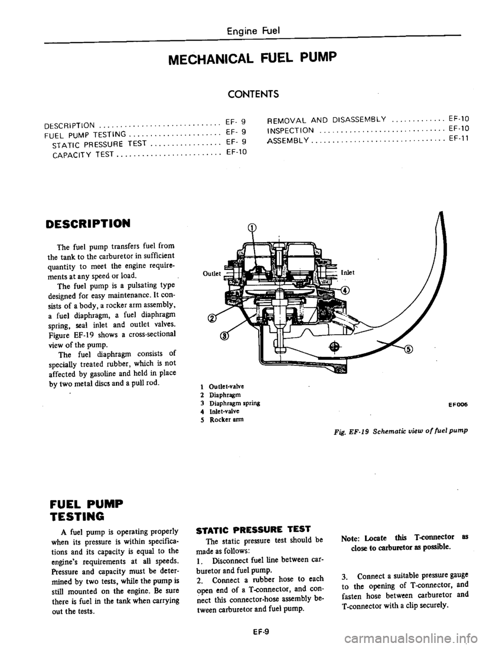
DESCRIPTION
The
fuel
pump
transfers
fuel
from
the
tank
to
the
carburetor
in
sufficient
quantity
to
meet
the
engine
require
ments
at
any
speed
or
load
The
fuel
pump
is
a
pulsating
type
designed
for
easy
maintenance
It
con
sists
of
a
body
a
rocker
arm
assembly
a
fuel
diaphragm
a
fuel
diaphragm
spring
seal
inlet
and
outlet
valves
Figure
EF
19
shows
a
cross
sectional
view
of
the
pump
The
fuel
diaphragm
consists
of
specially
treated
rubber
which
is
not
affected
by
gasoline
and
held
in
place
by
two
metal
discs
and
a
pull
rod
FUEL
PUMP
TESTING
A
fuel
pump
is
operating
properly
when
its
pressure
is
within
specifica
tions
and
its
capacity
is
equal
to
the
engine
s
requirements
at
all
speeds
Pressure
and
capacity
must
be
deter
mined
by
two
tests
while
the
pump
is
still
mounted
on
the
engine
Be
sure
there
is
fuel
in
the
tank
when
carrying
out
the
tests
Engine
Fuel
MECHANICAL
FUEL
PUMP
CONTENTS
EF
9
EF
9
EF
9
EF
10
REMOVAL
AND
DISASSEMBLY
INSPECTION
ASSEMBL
Y
EF
10
EF
10
EF
11
1
1
Outlet
valve
2
Diaphragm
3
Diaphragm
spring
4
Inlet
valve
S
Rocker
ann
EF006
Fig
EF
19
Schematic
view
of
fuel
pump
STATIC
PRESSURE
TEST
The
static
pressure
test
should
be
made
as
follows
I
Disconnect
fuel
line
between
car
buretor
and
fuel
pump
2
Connect
a
rubber
hose
to
each
open
end
of
a
T
connector
and
con
nect
this
connector
hose
assembly
be
tween
carburetor
and
fuel
pump
Note
Locate
this
T
connector
as
close
to
carburetor
as
possible
3
Connect
a
suitable
pressure
gauge
to
the
opening
of
T
connector
and
fasten
hose
between
carburetor
and
T
connector
with
a
clip
securely
EF
9
Page 135 of 537

There
are
three
types
of
control
system
These
are
J
Closed
type
CIllnkcase
emission
control
system
Emission
Control
System
of
GENERAL
DESCRIPTION
2
Exhaust
emission
control
system
3
Evaporative
ell
lhsion
control
sys
tem
Pericxiic
inspection
and
required
seCV1Clng
of
these
systems
should
be
carried
out
to
reduce
harmful
emis
sions
to
a
minimum
CRANKCASE
EMISSION
CONTROL
SYSTEM
c
01
Lkf
If
1
TIL
II
tll
1
j
GUuuu
DESCRIPTION
This
system
returns
blow
by
gas
to
both
the
intake
manifold
and
carbure
tor
air
cleaner
The
positive
crankcase
ventilation
p
C
V
valve
is
provided
to
conduct
crankcase
blow
by
gas
to
the
intake
manifold
During
partial
throttle
operation
of
the
engine
the
intake
manifold
sucks
the
blow
by
gas
through
the
P
C
V
valve
Normally
the
capacity
of
the
valve
is
sufficient
to
handle
any
blow
by
and
a
small
amount
of
ventilating
air
4
c
Fresh
air
Blow
by
gas
The
ventilating
air
is
then
drawn
from
the
dust
side
of
the
cadlUretor
air
cleaner
tluough
the
tube
con
necting
carburetor
air
cleaner
to
rock
er
cover
into
the
crankcase
Under
full
tluottle
condition
the
manifold
vacuwn
is
insufficient
to
draw
the
blow
by
flow
tluough
the
valve
and
its
flow
goes
through
the
tube
connection
in
the
reverse
diree
tion
On
vehicles
with
an
excessively
high
blow
by
some
of
the
flow
will
go
through
the
tube
connection
to
carbu
retor
air
cleaner
under
all
conditions
1
Sealtypc
oil
level
gauge
2
Bame
plate
3
Flame
arrester
4
Filler
5
P
C
Y
valve
6
Steel
net
7
Bame
plate
EC716
Fig
EC
l
Crankcase
miaion
control
ay
tem
EC
2
INSPECTION
P
c
V
VALVE
AND
FILTER
Checking
P
C
V
valve
in
accord
ance
with
the
following
method
With
engine
running
at
idle
remove
the
ventilator
hose
from
P
C
V
valve
if
the
valve
is
working
a
hissing
noise
will
be
heard
as
air
passes
through
the
valve
and
a
strong
vacuwn
should
be
felt
immediately
when
a
fmger
is
placed
over
valve
inlet
Replace
P
C
V
valve
and
filter
in
accordance
with
the
maintenance
schedule
VENTILATION
HOSE
1
Check
hoses
and
hose
connec
tions
for
leaks
2
Disconnect
all
hoses
and
clean
with
compressed
air
If
any
hose
cannot
be
free
of
obstructions
replace
Ensure
that
flame
arrester
is
surely
inserted
in
hose
between
air
cleaner
and
rocker
cover
Page 141 of 537

Emission
Control
System
C
bur
tor
I
EC284
When
installing
this
valve
ensure
that
it
properly
oriented
Tlus
valve
shuuld
be
replaced
periodically
Refer
to
Maintenance
Schedule
Note
Carburetor
side
Black
DisInDutor
side
Brown
horn
distributor
To
carburetor
TOdi
ribUI0
carburClor
EC
lCiJr
Fig
EC
9
Operation
01
park
delay
value
INSPECTION
Remove
spark
delay
valve
2
Blow
air
through
port
on
carbure
tor
side
then
through
the
other
port
on
distributor
side
Spark
delay
valve
Distributor
side
1
One
way
umbrella
valve
2
Sintered
metal
disc
Fig
EC
8
Spark
delay
valve
is
in
good
condition
if
when
finger
is
placed
over
port
on
distributor
side
air
flow
resistance
is
greater
than
that
on
the
other
side
See
Figur
ET
lO
3
If
a
considerable
air
flow
resist
ance
is
fell
at
port
on
distributor
side
in
step
2
above
and
if
the
condition
of
spark
delay
valve
is
questionable
dip
port
on
carburetor
side
into
a
cup
filled
with
water
Blow
air
through
the
other
port
Small
air
bubbles
should
appear
Carburetor
side
Distributor
side
EC346
Fig
EC
IO
Checking
park
delay
valve
EC
8
EC219
Fig
EC
11
Checking
spark
d
tay
valve
Note
Be
careful
to
avoid
entry
of
oil
or
dirt
into
valve
AIR
INJECTION
SYSTEM
DESCRIPTION
The
Air
Injection
System
A
LS
is
aeSigiieino
iiiject
coin
pressed
air
sec
ODllary
air
corning
from
the
air
pump
into
the
exhaust
manifold
to
reduce
hydrocarbons
and
carbon
monoxide
in
exhaust
lri
s
through
re
combustion
There
are
two
types
of
A
I
S
One
type
is
mounted
on
California
models
and
the
other
is
on
non
California
models
The
non
California
type
con
sists
of
an
air
pump
air
cleaner
an
air
pump
a
relief
valve
a
check
valve
an
anti
backfIre
valve
an
air
gallery
and
hoses
The
California
type
has
in
addition
to
the
components
of
the
non
California
type
an
air
control
valve
and
an
emergency
air
relief
valve
These
valves
prevent
ahnonnal
tem
perature
rise
of
the
catalytic
converter
Page 193 of 537
NON
CALIFORNIA
MODELS
Engine
Electrical
System
IGNITION
CIRCUIT
CONTENTS
EE
26
CALIFORNIA
MODELS
EE
2B
NON
CALIFORNIA
MODELS
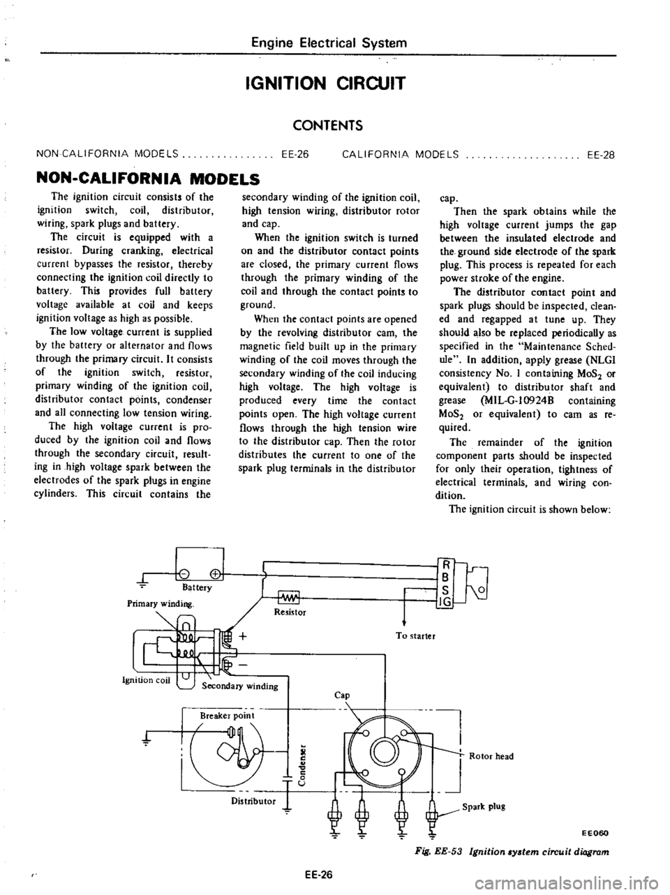
The
ignition
circuit
consists
of
the
ignition
switch
coil
distributor
wiring
spark
plugs
and
battery
The
circuit
is
equipped
with
a
resistor
During
cranking
electrical
current
bypasses
the
resistor
thereby
connecting
the
ignition
coil
directly
to
battery
This
provides
full
battery
voltage
available
at
coil
and
keeps
ignition
voltage
as
high
as
possible
The
low
voltage
current
is
supplied
by
the
battery
or
alternator
and
flows
through
the
primary
circuit
It
consists
of
the
ignition
switch
resistor
primary
winding
of
the
ignition
coil
distributor
contact
points
condenser
and
all
connecting
low
tension
wiring
The
high
voltage
current
is
pro
duced
by
the
ignition
coil
and
flows
through
the
secondary
circuit
result
ing
in
high
voltage
spark
between
the
electrodes
of
the
spark
plugs
in
engine
cylinders
This
circuit
contains
the
0
cl
Battery
Ignition
coil
secondary
winding
of
the
ignition
coil
high
tension
wiring
distributor
rotor
and
cap
When
the
ignition
switch
is
turned
on
and
the
distributor
contact
points
are
closed
the
primary
current
flows
through
the
primary
winding
of
the
coil
and
through
the
contact
points
to
ground
When
the
contact
points
are
opened
by
the
revolving
distributor
earn
the
magnetic
field
built
up
in
the
primary
winding
of
the
coil
moves
through
the
secondary
winding
of
the
coil
inducing
high
voltage
The
high
voltage
is
produced
every
time
the
contact
points
open
The
high
voltage
current
flows
through
the
high
tension
wire
to
the
distributor
cap
Then
the
rotor
distributes
the
current
to
one
of
the
spark
plug
terminals
in
the
distributor
Re5istor
To
starter
Secondary
winding
Cap
Breaker
point
f
Distributor
EE
26
cap
Then
the
spark
obtains
while
the
high
voltage
current
jumps
the
gap
between
the
insulated
electrode
and
the
ground
side
electrode
of
the
spark
plug
This
process
is
repeated
for
each
power
stroke
of
the
engine
The
distributor
contact
point
and
spark
plugs
should
be
inspected
clean
ed
and
regapped
at
tune
up
They
should
also
be
replaced
periodically
as
specified
in
the
Maintenance
Sched
ule
In
addition
apply
grease
NLGl
consistency
No
I
containing
MoS2
or
equivalent
to
distributor
shaft
and
grease
MIL
G
l0924B
containing
MoS2
or
equivalent
to
cam
as
reo
quired
The
remainder
of
the
ignition
component
parts
should
be
inspected
for
only
their
operation
tightness
of
electrical
terminals
and
wiring
con
dition
The
ignition
circuit
is
shown
below
IR
IB
I
is
21
J
g
Rotor
head
EE060
Fig
EE
53
Ignition
ydem
circuit
diagram
Page 198 of 537
CHECKING
AND
ADJUSTMENT
CAP
AND
ROTOR
HEAD
Cap
and
rotor
head
should
be
in
spected
periodically
as
specified
in
the
Maintenance
Schedule
Remove
cap
and
clean
all
dust
and
carbon
deposits
from
cap
and
rotor
If
cap
is
cracked
or
is
leaking
replace
with
a
De
one
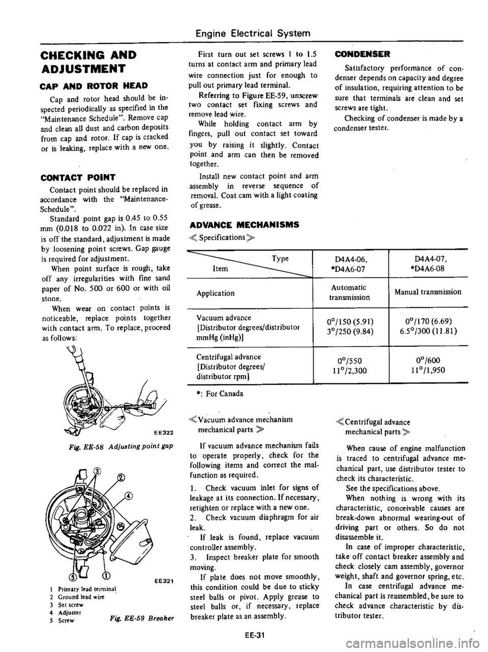
CONTACT
POINT
Contact
point
should
be
replaced
in
accordance
with
the
Maintenance
Schedule
Standard
point
gap
is
0
45
to
0
55
mm
O
OIS
to
0
022
in
In
case
size
is
off
the
standard
adjustment
is
made
by
loosening
point
screws
Gap
gauge
is
required
for
adjustment
When
point
surface
is
rough
take
off
any
irregularities
with
fine
sand
paper
of
No
500
or
600
or
with
oil
stone
When
wear
on
contact
points
is
noticeable
replace
points
together
with
contact
arm
To
replace
proceed
as
follows
EE322
Fig
EE
58
Adju
ting
point
gap
EE321
I
Primary
lead
termina
2
Ground
lead
wire
3
Set
screw
4
Adjuster
5
Screw
Fig
EE
59
Breaker
Engine
Electrical
System
First
turn
out
set
screws
1
to
1
5
turns
at
contact
arm
and
primary
lead
wire
connection
just
for
enough
to
pull
out
primary
lead
terminal
Referring
to
Figure
EE
59
unSCrew
two
contact
set
fixing
screws
and
remove
lead
wire
While
holding
contact
arm
by
fingers
pull
out
contact
set
toward
you
by
raising
it
slightly
Contact
point
and
afm
can
then
be
removed
together
Install
new
contact
point
and
arm
assembly
in
reverse
sequence
of
removal
Coat
cam
with
a
light
coating
of
grease
ADVANCE
MECHANISMS
Specifications
Application
Vacuum
advance
Distributor
degrees
distributor
mmHg
inHg
Centrifugal
advance
Distributor
degrees
distribu
tor
rpm
For
Canada
Vacuum
advance
mechanism
mechanical
parts
If
vacuum
advance
mechanism
fails
to
operate
properly
check
for
the
following
items
and
correct
the
mal
function
as
required
1
Check
vacuum
inlet
for
signs
of
leakage
at
its
connection
Ifnecessacy
retighten
or
replace
with
a
new
one
2
Check
vacuum
diaphragm
for
air
leak
If
leak
is
found
replace
vacuum
controller
assembly
3
Inspect
breaker
plate
for
smooth
moving
If
pia
te
does
not
move
smoothly
this
condition
could
be
due
to
sticky
steel
balls
or
pivot
Apply
grease
to
steel
balls
or
if
necessary
replace
breaker
plate
as
an
assembly
EE
31
CONDENSER
Satisfactory
performance
of
con
denser
depends
on
capacity
and
degree
of
insulation
requiring
attention
to
be
sure
that
terminals
are
clean
and
set
screws
are
tight
Checking
of
condenser
is
made
by
a
condenser
tester
D4A4
06
D4A6
07
D4A4
07
D4A6
0S
Automatic
transmission
Manual
transmission
00
150
5
91
30
250
9
S4
00
170
6
69
6
50
300
1I
S1
00
550
11
0
2
300
00
600
110
1
950
Centrifugal
advance
mechanical
parts
When
cause
of
engine
malfunction
is
traced
to
centrifugal
advance
me
chanical
part
use
distributor
tester
to
check
its
characteristic
See
the
specifications
above
When
nothing
is
wrong
with
its
characteristic
conceivable
causes
are
break
down
abnormal
wearing
out
of
driving
part
or
others
So
do
not
disassemble
it
In
case
of
improper
characteristic
take
off
contact
breaker
assembly
and
check
closely
cam
assembly
governor
weight
shaft
and
governor
spring
etc
In
case
centrifugal
advance
me
chanical
part
is
reassembled
be
sure
to
check
advance
characteristic
by
dis
tributor
tester
Page 201 of 537

t3
l
l
J
@
r
9
V
fW
@
@
CHECKING
AND
ADJUSTMENT
CAP
AND
ROTOR
HEAD
Cap
and
rotor
head
must
be
in
spected
periodically
as
specified
in
the
Maintenance
Schedule
Remove
cap
and
clean
all
dust
and
carbon
deposits
from
cap
and
rotor
from
time
to
time
If
cap
is
cracked
or
is
leaking
replace
with
a
new
one
AIR
GAP
Standard
air
gap
is
0
2
to
0
4
mm
0
008
to
0
016
in
If
the
gap
is
off
the
standard
adjustment
mould
be
made
by
loos
ening
pick
up
coil
screws
Gap
gauge
is
required
for
adjust
ment
Air
gaps
must
be
checked
from
time
to
time
Air
gap
0
2
to
0
4
mm
0
008
to
0
016
in
Engine
Electrical
System
tl
@
9
EE328
Fig
EE
67
Checking
oir
gap
To
remove
pick
up
cail
disconnect
distributor
harness
at
terminal
block
and
remove
screw
securing
pick
up
coil
ADVANCE
MECHANISMS
Specifications
Type
Item
Vacuum
advance
Distributor
degrees
Distributor
mmHg
inHg
Centrifugal
advance
Distributor
degrees
Distributor
cpm
EE34
1
Cap
assembly
2
Rotor
head
a55embly
3
Roll
pin
4
ReJuctor
S
Pick
up
coil
6
Contactoi
7
Breaker
plate
assembly
8
Packing
9
Rotor
shaft
10
Governor
spring
11
Governor
weigh
t
12
Shaft
a
Jscmbly
13
Cap
setter
14
Vacuum
controller
15
Housing
16
Fixing
plate
17
O
ring
18
Collar
EE327
Fig
EE
66
Exploded
view
of
di3tributor
assembly
and
distributor
harness
to
their
positions
EE329
Fig
EE
68
Remouing
pick
up
coil
D4F4
04
D4F4
Q3
Manual
Automatic
00
150
5
91
30
250
9
84
00
550
110
2
300
00
600
110
1
950