key DATSUN PICK-UP 1977 User Guide
[x] Cancel search | Manufacturer: DATSUN, Model Year: 1977, Model line: PICK-UP, Model: DATSUN PICK-UP 1977Pages: 537, PDF Size: 35.48 MB
Page 161 of 537
I
Emission
Control
System
Ignition
switch
Ignition
key
Off
T
I
I
I
Battery
I
J
77
77
Relay
J
Floor
temperature
sensing
swi
tch
Floor
temperature
warning
lamp
77
77
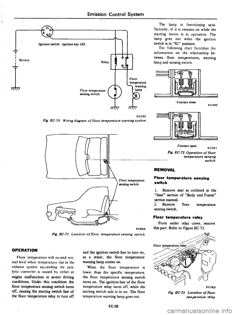
EC332
Fig
EC
70
Win
ng
diagram
of
floor
temperature
warning
system
r
l
J
@
1
Floor
temperature
Ij
cr
EC556
Fig
EC
71
Location
of
iJoor
temperature
sensing
switch
OPERATION
Floor
temperature
will
exceed
nor
mal
level
when
temperature
rise
in
the
exhaust
system
succeeding
the
cata
lytic
converter
is
caused
byeilher
an
engine
malfunction
or
severe
driving
conditions
Under
this
condition
the
floor
temperature
sensing
switch
turns
off
causing
the
starting
switch
line
of
the
floor
temperature
relay
to
turn
off
and
the
ignition
switch
line
to
turn
on
as
a
result
the
floor
temperature
warning
lamp
comes
on
When
the
floor
temperature
is
lower
t
an
the
specific
temperature
the
floor
temperature
sensing
switch
turns
on
The
ignition
line
of
the
floor
temperature
relay
turns
off
while
the
starting
switch
side
is
in
on
The
floor
temperature
warning
lamp
goes
out
EC
2B
The
lamp
is
functioning
sa
tis
factorily
if
it
is
remains
on
while
the
starting
motor
is
in
operation
The
lamp
goes
out
when
the
ignition
switch
is
in
IG
position
The
foUowing
chart
furnishes
the
information
on
the
relationship
be
tween
floor
temperatures
warning
lamp
and
sensing
switch
L
Contact
close
ECJ40
I
Contaclopen
ECJ41
Fig
EC
72
Operation
of
floor
t
mperature
sen6ing
6witch
REMOVAL
Floor
temperature
sensing
switch
1
Remove
seat
Seat
section
of
service
manual
2
Remove
sensing
sWitch
as
outlined
in
the
Body
and
Frame
floor
temperature
Floor
temperature
relay
From
under
relay
cover
remove
this
part
Refer
to
Figure
EC
73
Floortemperature
EC783
Fig
EC
73
Location
of
floor
ttmperature
relay
Page 173 of 537
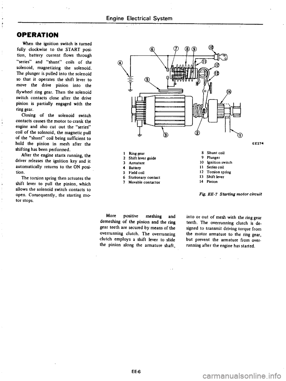
OPERATION
When
the
ignition
switch
turned
fully
clockwise
to
the
START
posi
tion
battery
current
flows
through
series
and
shunt
coils
of
the
solenoid
magnetizing
the
solenoid
The
plunger
is
pulled
into
the
solenoid
so
that
it
operates
the
shift
lever
to
move
the
drive
pinion
into
the
flywheel
ring
gear
Then
the
solenoid
switch
contacts
close
after
the
drive
pinion
is
partially
engaged
with
the
ring
gear
Closing
of
the
solenoid
switch
contacts
c
uses
the
motor
to
crank
the
engine
and
also
cut
out
the
series
coil
of
the
solenoid
the
magnetic
pull
of
the
shunt
coil
being
sufficient
to
hold
the
pinion
in
mesh
after
the
shifting
has
been
performed
After
the
engine
starts
running
the
driver
releases
the
ignition
key
and
it
automatically
returns
to
the
ON
posi
tion
The
torsion
spring
then
actuates
the
shift
lever
to
pull
the
pinion
which
allows
the
solenoid
swi
tch
contacts
to
open
Consequently
the
starting
mo
tor
stops
Engine
Electrical
System
I
I
Ring
gear
2
Shift
lever
guide
3
Armature
4
Battery
5
Field
coil
6
Stationary
contact
7
Monble
contactor
More
positive
meshing
and
demeshing
of
the
pinion
and
the
ring
gear
teeth
are
secured
by
means
of
the
overrunning
clutch
The
overruIUling
clutch
employs
a
shift
lever
to
slide
the
pinion
along
the
armature
shaft
EE
6
F
l
cp
o
r
1
I
I
W
m
EE274
8
Shunt
coil
9
Plunger
10
Ignition
switch
11
Series
coil
12
Torsion
spring
13
Shift
lever
14
Pinion
Fig
EE
7
Starting
motor
circuit
into
or
out
of
mesh
with
the
ring
gear
teeth
The
overrunning
clutch
is
de
signed
to
transmit
driving
torque
from
the
motor
armature
to
the
ring
gear
but
prevent
the
armature
from
over
running
after
the
engine
has
started
Page 236 of 537
Manual
Transmission
4
SPEED
TRANSMISSION
TYPE
F4W71B
CONTENTS
DESCRIPTION
REMOVAL
DISASSEMBL
Y
TRANSMISSION
CASE
DISASSEMBLY
D
ISASSEMBL
Y
OF
GEAR
ASSEMBLY
REAR
EXTENSION
DISASSEMBLY
ADAPTER
PLATE
DISASSEMBLY
INSPECTION
TRANSMISSION
CASE
AND
REAR
EXTENSION
HOUSING
BEARING
GEARS
AND
SHAFTS
BAULK
RING
Oil
SEAL
ASSEMBL
Y
FRONT
COVER
ASSEMBLY
REAR
EXTENSION
ASSEMBLY
ADAPTER
PLATE
ASSEMBLY
GEAR
ASSEMBLY
TRANSMISSION
ASSEMBLY
INSTALLATION
MT
2
MT
4
MT
4
MT
4
MT
5
MT
B
MT
8
MT
8
MT
B
MT
8
MT
8
MT
9
MT
9
MT
9
MT
9
MT
9
MT
9
MT
9
MT13
MT14
DESCRIPTION
pUshed
the
inner
teeth
of
the
coupling
sleeve
slide
over
the
synchronizer
hub
and
mesh
with
the
outer
teeth
which
are
provided
on
the
mainshaft
gear
The
synchronizer
hub
is
fitted
to
the
mainshaft
by
splines
so
the
main
shaft
gear
turns
together
with
the
mainshaft
The
baulk
ring
serves
to
synchro
nile
the
coupling
sleeve
and
mainshaft
gear
Placing
the
control
lever
in
reverse
position
brings
the
reverse
idler
gear
into
mesh
with
mainshaft
reverse
gear
The
transmission
is
of
a
4
speed
forward
fully
synchronized
constant
mesh
type
that
uses
helical
gears
The
reverse
gear
is
ofa
sliding
mesh
type
using
spur
gears
In
construction
the
main
drive
gear
is
meshed
with
the
counter
drive
gear
which
is
keyed
to
the
countershaft
The
forward
speed
gears
on
the
coun
tershaft
are
in
constant
mesh
with
the
mainshaft
gears
which
ride
on
the
mainshaft
freely
through
the
needle
bearing
When
shifting
is
accom
The
transmission
assembly
consists
of
three
main
parts
a
transmission
case
with
clutch
housing
adapter
plate
to
which
an
gears
and
shafts
are
installed
and
rear
extension
The
cast
iron
adapter
plate
supports
the
mainshaft
countershaft
reverse
idler
shaft
and
three
fork
rods
and
bolted
at
the
front
to
the
transmission
case
and
at
the
rear
to
the
rear
extension
by
means
of
through
bolts
By
removing
these
through
bolts
all
gears
and
shafts
are
stripped
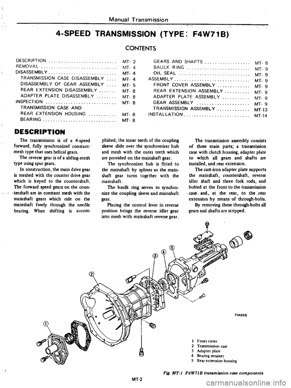
e
TM
858
1
Front
cover
2
Transmission
case
3
Adapter
plate
4
Bearing
retainer
5
Rear
extension
hOUsing
Fig
MT
1
F4W71B
lrammiasion
case
compon
nt
MT
2
Page 241 of 537
Manual
Transmission
M
in
drlv
g
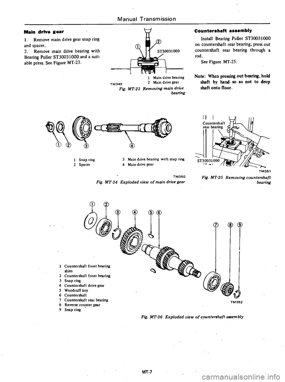
r
1
Remove
main
drive
gear
snap
ring
and
spacer
2
Remove
main
drive
bearing
with
Bearing
Puller
ST30031000
and
a
suit
able
piess
See
Figure
MT
23
TM349
Fig
MT
23
1
Main
drive
bearing
2
Main
drive
gear
Removing
main
drive
bearing
cl
iiiiiE
l
1
Snap
ring
2
Spacer
3
Main
drive
bearing
with
snap
ring
4
Main
drive
gear
TM350
Fig
MT
24
Exploded
view
of
main
drive
gear
e
q
1
f
1
Countershaft
front
bearing
shim
2
Countenhaft
front
bearing
3
Snap
ring
4
Countenhaft
drive
gear
5
Woodruff
key
6
Countenhaft
1
Countershaft
rear
bearing
8
Reverse
counter
gear
9
Snap
ring
Count
r
h
ft
mbl
Install
Bearing
Puller
STJOO31000
on
countershaft
rear
bearing
press
out
countershaft
rear
bearing
through
a
rod
See
Figure
MT
25
Note
When
pressing
out
bearing
hold
shaft
by
hand
so
as
not
to
drop
shaft
onto
floor
III
TM351
Fig
MT
25
Removing
countershaft
bearing
@
@
j
i
TM352
Fig
MT
26
Exploded
view
of
counte
haft
auembly
MT
7
Page 244 of 537

Malnshaft
assembly
I
Assemble
2nd
gear
needle
bear
ing
2nd
gear
baulk
ring
1st
2nd
speed
synchronizer
assembly
st
gear
baulk
ring
I
st
gear
bush
needle
bear
ing
I
st
gear
steel
ball
and
thrust
washer
on
mainshaft
Before
installing
a
steel
ball
apply
grease
to
it
See
Figure
MT
36
TM358
Fig
MT
36
l
talling
thrust
washer
2
Set
Transmission
Press
Stand
KV311
00400
and
place
adapter
plate
assembly
on
it
See
Figure
MT
37
For
counterman
and
reverse
idler
shaft
For
main5haft
and
reverse
tdler
haft
V31100400
J
UJ
V
TM438
Holes
for
reverse
Idler
shaft
Fig
MT
37
Tromm
inion
PreS3
S
tond
3
Install
mainshaft
assembly
to
adapter
plate
assembly
Be
sure
to
place
bearing
squarely
against
shaft
and
press
it
into
place
on
shaft
gradu
ally
See
Figure
MT
38
KV31100400
TM439
Fig
MT
38
Installing
mai
haft
em
bly
Manual
Transmission
Countershaft
assembly
I
Place
new
woodruff
keys
in
grooves
in
countershaft
and
tap
them
lightly
until
they
are
seated
securely
Use
a
soft
hammer
to
avoid
dam
aging
keys
2
Place
adapter
plate
assembly
and
mainshaft
assembly
so
that
counter
shaft
rear
bearing
rests
on
Transmis
sion
Press
Stand
KV31100400
prop
erly
3
Install
countershaft
into
adapter
plate
by
pressing
it
See
Figure
MT
39
TM440
Fig
MT
39
l
talling
countersha
t
4
Position
3rd
gear
needle
bearing
fnaiiiSh
ifOfd
gear
baulk
ring
and
3rd
4th
synchronizer
assembly
on
the
front
of
mainshaft
S
Ins
iall
thrust
washer
on
mainshaft
and
e
ure
it
with
snap
ring
of
proper
thickness
that
will
fit
the
groove
in
mainshaft
See
Figure
MT
40
Available
snap
ring
No
Thickness
mm
in
I
2
3
1
4
0
055
1
5
0
059
1
6
0
063
TM441
Fig
MT
40
l
talling
snap
ring
MT
l0
Main
drive
gear
assembly
1
Using
Transmission
Adapter
ST23800000
press
main
drive
bearing
onto
the
shaft
of
main
drive
gear
Make
sure
that
snap
ring
groove
on
shaft
clears
bearing
2
Place
main
drive
bearing
spacer
on
main
drive
bearing
and
secure
main
drive
bearing
with
thicker
snap
ring
that
will
eliminate
end
play
See
Figure
MT
4l
Available
snap
ring
No
Thickness
mm
in
2
3
4
5
6
1
80
0
0709
1
87
0
0736
1
94
0
0764
2
01
0
0791
2
08
0
0819
2
15
0
0846
CD
I
TM364
Fig
MT
41
Installing
snap
ring
3
Position
baulk
ring
on
cone
sur
face
of
main
drive
gear
Apply
gear
oil
to
mainshaft
pilot
bearing
and
install
it
on
mainshaft
Assemble
main
drive
gear
assembly
on
the
front
end
of
mainshafl
4
Press
counter
drive
gear
onto
countershaft
with
Counter
Gear
Drift
ST23860000
by
meshing
gears
and
secure
counter
drive
gear
with
thicker
snap
ring
See
Figures
MT
42
and
MT
43
Note
Be
sure
to
drive
in
counter
drive
gear
and
main
drive
gear
simultaneously
Page 313 of 537
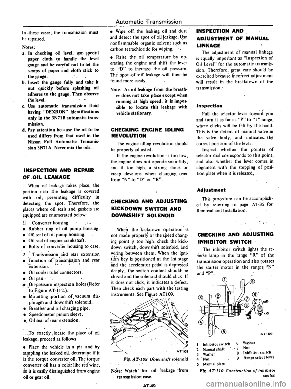
In
these
cases
the
transmission
must
be
repaired
Notes
a
In
checking
oil
level
use
special
paper
cloth
to
handle
the
level
gauge
and
be
careful
not
to
let
the
scraps
of
paper
and
cloth
stick
to
the
gauge
b
Insert
the
gauge
fully
and
take
it
out
quickly
before
splashing
oil
adheres
to
the
gauge
Then
observe
the
level
c
Use
automatic
transmission
fluid
having
DEXRON
identifications
only
in
the
3N71B
automatic
trans
mission
d
Pay
attention
because
the
oil
to
be
used
differs
from
that
used
in
the
Nissan
Full
Automatic
TranSJTIis
sion
3N71A
Never
mix
the
oils
INSPECTION
AND
REPAIR
OF
OIL
LEAKAGE
When
oil
leakage
takes
place
the
portion
near
the
leakage
is
covered
with
oil
presenting
difficulty
in
detecting
the
spot
Therefore
the
places
where
oil
seals
and
gaskets
are
equipped
are
enumerated
below
11
Converter
housing
Rubber
ring
of
oil
pump
housing
Oil
seal
of
oil
pump
housing
Oil
seal
of
engine
crankshaft
Bolts
of
converter
housing
to
case
2
Trarismission
and
rear
extension
Junction
of
transm
ss
ion
and
rear
extension
J
Oil
cooler
tube
connectors
Oil
pan
Oil
pressure
inspection
holes
Refer
to
Figure
AT
il2
Mounting
portion
of
vacuum
dia
phragm
and
downshift
solenoid
Breather
and
oil
charging
pipe
Speedometer
pinion
sleeve
Oil
se
l
of
rear
extension
To
exactly
locate
the
place
of
oil
leaka
le
proceed
as
follows
Place
the
vehicle
in
a
pit
and
by
sampling
the
leaked
oil
determine
if
it
is
the
torque
converter
oil
The
torque
converter
oil
has
a
color
like
r
d
wine
So
it
is
easily
distinguished
from
engine
oil
or
gear
oil
Automatic
rransmission
Wipe
off
the
leaking
oil
and
dust
and
deiecl
the
spol
of
oil
eakage
l
se
nonflammable
organic
solve
t
s
ch
as
carbon
tetrachloride
for
wiping
Raise
the
oil
tcmperalure
by
op
erating
the
engine
and
shift
the
lever
to
D
to
increase
the
oil
pressure
The
spot
of
oil
lcakage
will
then
be
found
more
easily
Note
As
oil
leakage
from
the
breaih
er
does
not
take
place
except
when
running
at
high
speed
it
is
impos
sible
to
locate
this
leakage
with
vehicle
stationary
CHECKING
ENGINE
IDLING
REVOLUTION
The
engine
idling
revolution
should
be
properly
adjusted
If
the
engine
revolution
is
too
low
the
engine
does
not
operate
smoothly
and
if
too
high
a
strong
shock
or
creep
develops
when
changing
over
from
N
to
D
or
R
CHECKING
AND
ADJUSTING
KICK
DOWN
SWITCH
AND
DOWNSHIFT
SOLENOID
When
the
kickdown
operation
is
not
made
properly
or
the
speed
chang
ing
point
s
too
high
check
the
kick
down
switch
downshift
solenoid
and
wiring
between
them
When
the
igni
li
n
key
is
pqsitioned
a
t
the
I
st
stage
nd
the
accelerator
pedal
is
depressed
deeply
the
switch
contact
should
be
closed
and
the
solenoid
should
click
If
it
does
not
click
it
indicates
a
defect
Then
check
each
part
with
the
testing
instruments
See
Figure
ATl09
d
I
t
AT10S
Fig
AT
109
Downshift
solenoid
Note
Watch
for
oil
leakage
from
transmission
case
AT
4Q
INSPECTION
AND
ADJUSTMENT
OF
MANUAL
LINKAGE
The
adjustmcnt
of
manual
linkage
is
equaUy
important
as
Inspection
of
Oil
Level
for
the
automatic
transmis
sion
Thereforc
great
care
should
be
exercised
because
incorrect
adjustment
will
rcsult
in
the
brcakdown
of
the
transmission
Inspection
Pull
the
selector
lever
toward
you
and
turn
it
as
far
as
P
to
I
range
wherc
clicks
will
be
felt
by
the
hand
This
is
the
detcnt
of
manual
valve
in
the
valve
body
and
indicates
th
correct
position
of
the
lever
Inspect
whether
the
pointer
of
selector
dial
corresponds
to
this
point
and
also
whether
the
lever
comes
in
alignment
with
the
stepping
of
posi
tion
plate
when
it
is
released
Adjustment
This
procedure
can
be
accomplish
ed
by
refcrring
to
page
AT
35
for
Removal
and
Installa
tion
CHECKING
AND
ADJUSTING
INHIBITOR
SWITCH
The
inhibitor
switch
lights
the
re
verse
lamp
in
the
range
R
of
the
transmission
operatio
l
and
also
rotates
the
starter
motor
in
the
ranges
N
and
P
CD
@
b
ell
If
L
t
7
4l
@
1l
j7
@
@
@
dl
AT109
6
Washer
7
Nut
8
Inhibitor
switch
9
Range
select
lever
t
Inhibitor
switch
2
Manual
shaft
3
Washer
4
Nut
5
Manual
plate
Fig
AT
110
Construction
of
inhibitor
switch
Page 321 of 537

Automatic
Transmission
TROUBLE
SHOOTING
GUIDE
FOR
3N71B
AUTOMATIC
TRANSMISSION
Order
Test
item
Checking
Oil
level
gauge
2
Downshift
solenoid
3
Manuallinkage
L
4
Inhibitor
switch
5
Engine
idling
rpm
6
Vacuum
pressure
of
vacuum
pipe
7
Operation
in
each
range
8
Creep
of
vehicle
Stall
test
I
Oil
pressure
before
tesling
1
2
Stall
test
3
Oil
pressure
after
testing
Road
test
Slow
acceleration
I
st
2nd
2nd
3rd
2
Quick
acceleration
lst
2nd
2nd
3rd
3
Kick
down
operation
3rd
2nd
or
2nd
1st
Procedure
Check
gauge
for
oil
level
and
leakage
before
and
after
each
test
Check
for
sound
of
operating
solenoid
when
depressing
accelerator
pedal
fully
with
ignition
key
ON
Check
by
shifting
into
P
lR
IN
D
2
and
I
ranges
with
selector
lever
Check
whether
starter
operates
in
N
and
p
ranges
only
and
whether
reverse
lamp
operates
in
R
range
only
Check
whelher
idling
rpm
meet
standard
Check
whether
vacuum
pressure
is
more
than
450
mmHg
in
idling
and
whether
it
decreases
with
increasing
rpm
Check
whether
transmission
engages
positively
by
shifting
N
0
N
2
N
l
I
and
N
R
range
while
idling
with
brake
applied
Check
whether
there
is
any
creep
in
D
2
R
ranges
and
Measure
line
pressures
in
D
2
I
and
R
range
while
idling
Measure
engine
rpm
and
line
pressure
in
D
2
I
and
R
ranges
during
full
throttle
operati
n
Notes
a
Temperature
of
torque
converter
oil
used
in
test
should
be
from
600
to
1000C
1400
to
2120F
i
e
sufficiently
warmed
up
but
not
overheated
b
To
cool
oil
between
each
stall
test
for
D
2
I
and
R
ranges
idle
engine
i
e
rpm
at
about
1
200
rpm
for
more
than
1
minute
in
P
range
Measurement
time
must
not
be
more
than
5
seconds
Same
as
item
I
Check
vehide
speeds
and
engine
cpm
in
shifting
up
Ist
2nd
range
and
2nd
Jo3rd
range
while
running
with
lever
in
D
range
and
engine
vacuum
pressure
of
about
200
I11I1lHg
Same
as
item
1
above
except
with
engine
vacuum
pressure
of
0
mmHg
i
e
in
position
just
before
kickdown
Check
whether
the
kickdown
operates
and
measure
the
time
delays
while
running
at
30
40
50
60
70
km
h
18
25
30
37
43
MPH
in
D3
range
AT
57
Page 391 of 537

REMOVAL
Referring
to
Figure
BR
29
remove
parts
in
numerical
order
enumerated
1
cD
2
BR17S
Fig
BR
29
Removal
method
of
Mcuter
Vae
DISASSEMBLY
When
disassembling
Master
Vac
ob
serve
the
following
instructions
a
Thoroughly
clean
mud
or
dust
from
Master
Vac
b
Extreme
care
should
be
taken
not
to
allow
dirt
dust
water
or
any
other
foreign
matter
into
any
com
ponent
parts
Be
sure
to
select
a
clean
place
before
disassembly
or
assembly
c
Mark
mating
joints
so
that
they
may
be
installed
exactly
in
their
original
positions
d
Keep
all
disassembled
parts
arranged
properly
so
that
they
may
readily
be
assembled
at
any
time
e
Clean
rubber
parts
and
synthetic
resin
parts
in
alcohol
f
Mter
all
disassembled
parts
are
cleaned
in
a
suitable
clean
solvent
place
on
a
clean
work
bench
Use
care
not
to
allow
dirt
and
dust
to
come
into
contact
with
these
parts
1
Install
spacer
on
rear
shell
spacer
temporarily
Place
Master
Vac
in
a
vise
Use
soft
jaws
2
Remove
clevis
and
lock
nut
De
tach
valve
body
guard
rW
ID
1
Clevis
2
Lock
nut
3
Valve
body
guard
BRD7S
Fig
BR
30
Removing
rear
hell
Brake
System
3
Identify
front
shell
and
rear
shell
clearly
so
that
they
may
be
reassem
bled
in
their
original
positions
from
which
they
were
withdrawn
Bolts
attached
on
dashboard
are
not
the
same
in
pitch
4
Using
Master
Vac
Wrench
ST08080000
remove
rear
shell
seal
assembly
and
disassemble
diaphragm
plate
assembly
front
shell
assembly
diaphragm
spring
and
push
rod
assem
bly
f
Q
BA076
Fig
BR
31
Removing
reor
shell
Rear
shell
seal
Pry
off
retainer
with
use
of
screw
driver
as
shown
and
detach
bearing
and
seal
Note
Do
not
disassemble
seal
assem
bly
unless
absolutely
necessary
Whenever
this
is
to
be
removed
use
care
not
to
damage
it
BRD7S
Fig
BR
32
Removing
retainer
Diaphragm
plate
Place
diaphragm
plate
assembly
on
a
clean
work
bench
Detach
dia
phragm
from
groove
in
plate
as
shown
BR
16
BA079
FlIf
BR
33
Separating
diaphragm
2
Using
a
screwdriver
as
shown
evenly
pry
air
silencer
retainer
until
it
is
detached
from
diaphragm
plate
as
sembly
Note
Never
use
a
hammer
to
remove
this
retainer
since
this
win
be
the
sure
y
of
damaging
it
BA322
Fig
BR
34
Removing
air
silencer
retainer
3
Pull
out
valve
plunger
stop
key
and
withdraw
silencer
and
plunger
assembly
Note
To
remove
valve
plunger
stop
key
properly
proceed
as
follows
With
key
hole
facing
down
lightly
push
valve
operating
rod
simulta
neously
while
applying
vibration
to
it
BA180
Fig
BR
35
Pulling
out
top
key
Page 392 of 537

BA1Bl
Fig
BR
36
Remouing
ualue
operating
rod
assembly
4
Withdraw
reaction
disc
BA286
Fig
BR
37
Remouing
reaction
disc
Front
shell
seal
I
Detach
flange
from
front
shell
assembly
BR287
g
Fig
BR
38
Removing
lange
2
Withdraw
front
seal
assembly
INSPECTION
I
Check
poppet
assembly
for
condi
tion
If
it
shows
evidence
of
wear
or
damage
replace
it
and
valve
operating
rod
assembly
2
Check
other
component
parts
for
condition
If
any
part
shows
evidence
of
wear
or
damage
replace
it
with
a
new
one
Brake
System
ASSEMBLY
AND
ADJUSTMENT
Assemble
in
the
reverse
sequence
of
disassembly
Rear
shell
seal
1
Apply
a
coating
of
Master
Vac
grease
to
the
sealing
surface
and
lip
of
seal
and
install
that
seal
in
rear
shell
with
the
use
of
Master
Vac
Oil
Seal
Retainer
Drift
ST08060000
Fig
BR
39
Installing
oil
seal
Note
Referring
to
Figure
BR
40
in
stall
seal
in
place
by
properly
aligning
the
pawl
of
special
tool
with
seal
hole
Adjustment
is
cor
rect
when
specified
length
at
A
is
obtained
Length
A
6
7
to
7
Omm
0
264
to
0
276
in
BA1S5
Fig
BR
40
Length
at
A
Diaphragm
plate
I
Apply
a
thin
coating
of
grease
to
the
sliding
contact
portion
on
the
periphery
of
plunger
assembly
BR
17
1
SR1S6
Fig
BR
41
Requiring
grease
place
2
Install
plunger
assembly
and
silencer
in
diaphragm
plate
and
lightly
push
plunger
stop
key
in
place
Note
Diaphragm
plate
is
made
of
bakelite
Exercise
care
in
instaJJing
plunger
assembly
not
to
damage
diaphragm
plate
BROB3
Fig
BR
42
Inserting
stop
key
3
Before
installing
diaphragm
into
position
apply
a
thin
coating
of
mica
power
to
it
except
outer
diameter
and
seating
portion
with
which
shell
comes
into
contact
4
Before
installing
reaction
disc
in
place
on
diaphragm
plate
apply
a
thin
coating
of
Master
Vac
grease
Front
shell
seal
Before
installing
front
shell
seal
as
sembly
apply
a
coating
of
Master
Vac
grease
to
the
inner
wall
of
seal
and
front
sheU
with
which
seal
comes
into
contact
Final
sssembly
Apply
thin
coating
of
Master
Vac
grease
to
the
outer
edges
of
diaphragm
with
which
rear
and
front
shells
come
into
contact
before
instaIling
dia
phragm
in
position
2
Before
installing
push
rod
assem
bly
in
place
apply
a
coating
of
Master
Vac
grease
to
the
sliding
con
tact
surface
of
diaphragm
plate
Page 439 of 537

REMOVAL
AND
INSTALLATION
I
Open
door
2
Remove
inside
door
handle
es
cutcheon
3
Remove
pull
handle
4
Remove
arm
rest
5
Remove
regulator
handle
6
Remove
door
finish
7
Peel
off
water
seal
screen
8
Raise
door
glass
to
full
up
posi
tion
9
Remove
inside
door
lock
knob
10
Remove
rear
lower
sash
attach
iog
bolts
11
Disconnect
remote
control
rod
from
key
cylinder
and
outside
door
handle
12
Remove
three
door
lock
assem
bly
attaching
screws
13
Remove
two
inside
door
handle
attaching
screws
14
Together
with
inside
door
handle
take
out
door
lock
as
an
assembly
through
large
access
hole
in
door
panel
15
Remove
two
outside
door
handle
attaching
nuts
Outside
door
handle
can
then
be
taken
out
16
Remove
lock
plate
from
key
cylinder
and
detach
key
cylinder
17
To
install
door
lock
assembly
outside
and
inside
door
handles
and
key
cylinder
reverse
removal
pro
cedure
18
Lubricate
door
lock
with
grease
which
meets
the
requirements
of
MIL
G
I0924B
or
equivalent
as
listed
below
ALVANIA
GREASE
RA
SHELL
BEACON
325
ESSO
MOBILE
GREASE
22
MOBIL
Body
Frame
ADJUSTMENT
OutsIde
door
handle
Adjustment
of
play
in
outside
door
handle
is
controlled
by
play
adjust
ment
of
nylon
nut
on
threaded
end
of
outside
door
handle
rod
Correct
play
is
1
0
mm
0
039
in
or
below
as
measured
between
nylon
nut
and
locking
plate
Inside
door
handle
Elongated
hole
in
inside
door
handle
provides
for
play
adjustment
of
inside
door
handle
Correct
play
is
1
0
mm
0
039
ill
or
below
as
measured
at
control
rod
A
L
A
I
1
rB
I
B
REMOVAL
AND
INSTAUATION
I
Open
door
2
Free
weatherstrip
from
door
sash
clamp
BF
15
DOOR
LOCK
STRIKER
Adjustment
of
door
lock
striker
should
be
made
after
door
hinge
has
been
adjusted
correctly
Elongated
holes
three
provide
for
up
and
down
or
fore
and
aft
adjust
ment
to
establish
proper
engagement
between
door
lock
striker
and
door
lock
latch
WEATHERSTRIP
DESCRIPTION
The
weatherstrip
is
retained
by
clamp
to
the
door
sash
and
by
19
clips
to
the
door
panel
No
adhesive
is
used
to
retain
the
weatherstrip
to
door
Section
A
A
j
Section
B
B
BF645
Fig
BF
34
Door
weatheratrip
3
Pry
off
clips
from
door
panel
remove
weatherstrip
4
To
instaH
reverse
removal
pro
cedure