key DATSUN PICK-UP 1977 Owner's Manual
[x] Cancel search | Manufacturer: DATSUN, Model Year: 1977, Model line: PICK-UP, Model: DATSUN PICK-UP 1977Pages: 537, PDF Size: 35.48 MB
Page 467 of 537

Body
Electrical
System
Horn
switch
The
horn
switch
is
integral
with
the
turn
signal
and
dimmer
switch
as
sembly
Remove
switch
assembly
as
outlined
in
Turn
Signal
and
Dimmer
Switch
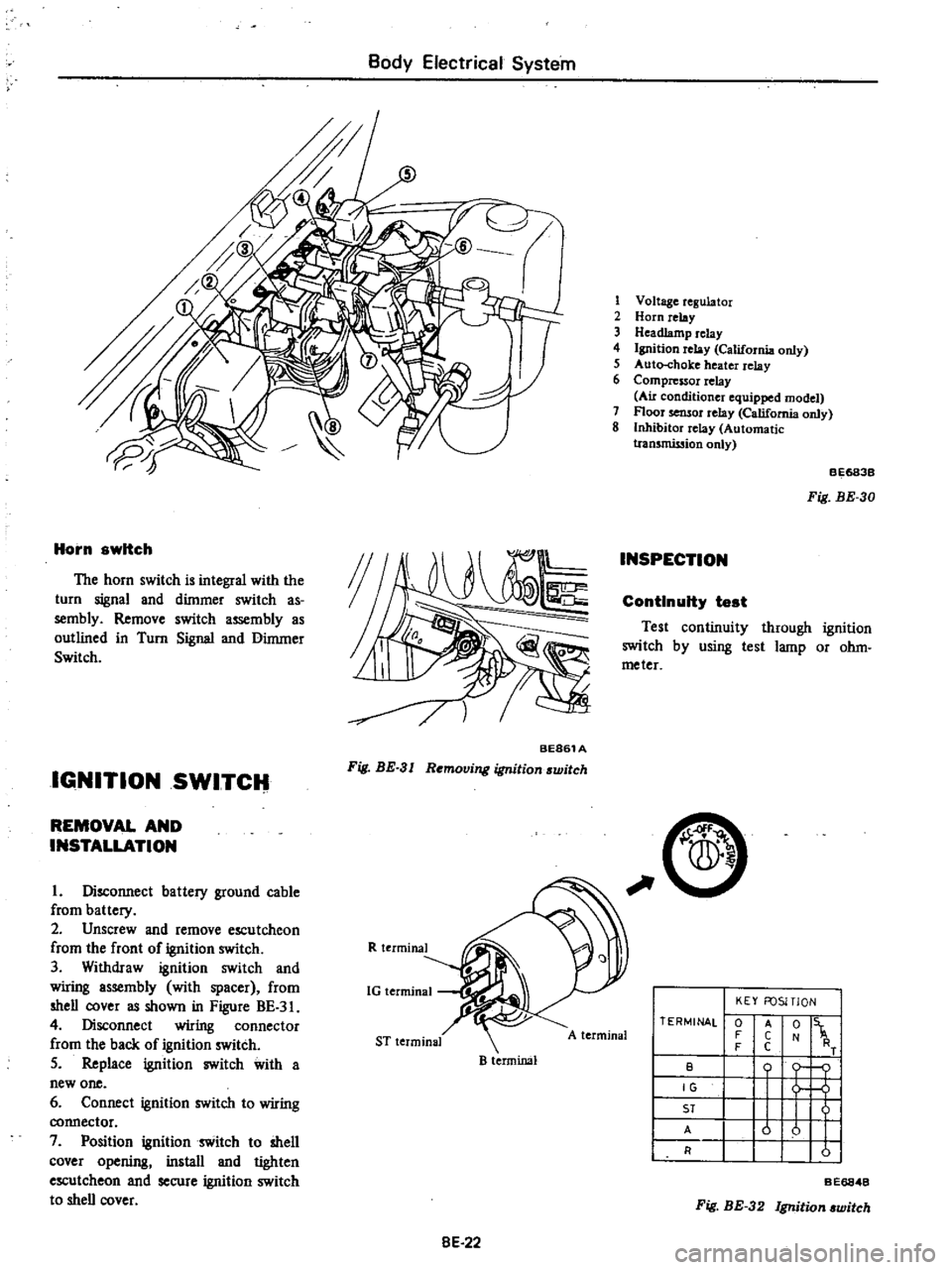
IGNITION
SWITCH
BE861A
Fig
BE
3
I
Removing
ignition
switch
REMOVAL
AND
INSTALLATION
I
Disconnect
battery
ground
cable
from
battery
2
Unscrew
and
remove
escutcheon
from
the
front
of
ignition
switch
3
Withdraw
ignition
switch
and
wiring
assembly
with
spacer
from
shell
cover
as
shown
in
Figure
BE
3
4
Disconnect
wiring
connector
from
the
back
of
ignition
switch
5
Replace
ignition
switch
with
a
new
one
6
Connect
ignition
switch
to
wiring
connector
7
Position
ignition
switch
to
shell
cover
opening
install
and
tighten
escutcheon
and
secure
ignition
switch
to
shell
cover
R
terminal
1G
terminal
ST
terminal
B
terminal
8E
22
1
Voltage
regulator
2
Horn
relay
3
Headlamp
relay
4
Ignition
relay
California
only
5
Auto
choke
heater
relay
6
Compressor
relay
Au
conditioner
equipped
model
7
Floor
sensor
relay
California
only
8
Inhibitor
relay
Automatic
tran5mission
only
INSPECTION
BE683B
Fig
BE
30
ContInuity
test
Test
continuity
through
ignition
switch
by
using
test
lamp
or
ohm
meter
C
A
terminal
TERMINAL
0
F
F
B
IG
ST
A
R
KEY
FOSITlON
t
1
o
j
u
u
I
I
A
C
C
Fig
BE
32
Ignition
witch
BE6848
Page 476 of 537

SEAT
BELT
WARNING
SYSTEM
DESCRIPTION
Except
Canada
When
the
ignition
switch
is
turned
to
the
ON
position
the
warning
lamp
comes
on
and
remains
on
for
4
to
8
seconds
The
warning
buzzer
sounds
for
4
to
8
seconds
intermittent
ly
if
the
driver
s
seat
belt
is
not
fastened
properly
The
seat
belt
warning
system
con
sists
of
a
driver
s
belt
switch
a
warning
buzzer
a
warning
lamp
a
timer
unit
and
an
ignition
switch
For
Canada
When
the
ignition
switch
is
turned
Body
Electrical
System
to
the
ON
position
the
warning
lamp
comes
on
and
the
warning
buz
zer
sounds
if
the
driver
s
seat
belt
is
not
fastened
properly
The
seat
belt
warning
system
con
sists
of
a
driver
s
belt
switch
a
warning
buzzer
a
warning
lamp
and
an
igni
tion
switch
REMOVAL
AND
INSTALLATION
Ignition
switch
Refer
to
page
BE
22
for
Removal
and
Installation
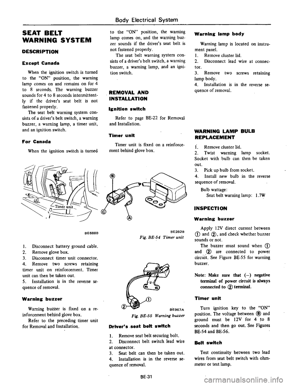
Timer
unit
Timer
unit
is
fIXed
on
a
reinforce
ment
behind
glove
box
BE688B
I
Disconnect
battery
ground
cable
2
Remove
glove
box
3
Disconnect
timer
unit
connector
4
Remove
two
screws
retaining
timer
unit
on
reinforcement
Timer
unit
can
then
be
taken
out
S
Installation
is
in
the
reverse
se
quence
of
removal
Warning
buzzer
Warning
buzzer
is
fIxed
on
a
re
inforcement
behind
glove
box
Refer
to
the
preceding
timer
unit
for
Removal
and
Installation
BE282B
Fig
BE
54
Timer
unit
BE967A
Fig
BE
55
Warning
buzzer
Driver
s
seat
belt
switch
I
Remove
seat
belt
ecuring
bolt
2
Disconnect
belt
switch
lead
wire
at
connector
3
Seat
belt
can
then
be
taken
out
4
Installation
is
in
the
reverse
se
quence
ofremoval
BE
31
Warning
lamp
body
Warning
lamp
is
located
on
instru
ment
panel
I
Remove
cluster
lid
2
Disconnect
lead
wire
at
connee
tor
3
Remove
two
screws
retaining
lamp
body
4
Installation
is
in
the
reverse
se
quence
of
removal
WARNING
LAMP
BULB
REPLACEMENT
I
Remove
cluster
lid
2
Twist
warning
lamp
socket
Socket
with
bulb
can
then
be
taken
out
3
Pick
up
bulb
from
socket
4
Install
new
bulb
in
the
reverse
sequence
of
removal
Bulb
wattage
Seat
belt
warning
lamp
I
7W
INSPECTION
Warning
buzzer
Apply
12V
direct
current
between
CD
and
@
and
check
whether
buzzer
sounds
or
not
The
buzzer
must
sound
when
CD
and
@
are
connected
to
power
circuit
See
Figure
BE
55
for
warning
buzzer
Note
Make
sure
that
negative
terminal
of
power
circuit
is
always
connected
to
@
terminal
Timer
unit
Turn
ignition
key
to
the
ON
position
The
voltage
between
@
and
ground
must
be
12V
for
4
to
8
seconds
and
then
go
out
See
Figures
BE
54
and
BE
56
Belt
switch
Test
continuity
between
two
lead
wires
from
seat
belt
switch
with
ohm
meter
or
test
lamp
Page 524 of 537

2
Install
the
clutch
assembly
on
the
crankshaft
Note
Key
should
be
set
on
crank
shaft
before
installing
clutch
assem
bly
3
Using
Clutch
Spanner
Wrench
hold
clutch
hub
With
socket
wrench
secure
clutch
hub
securing
bolt
Tightening
torque
Clutch
hub
securing
bolt
1
5
kg
m
II
ft
lb
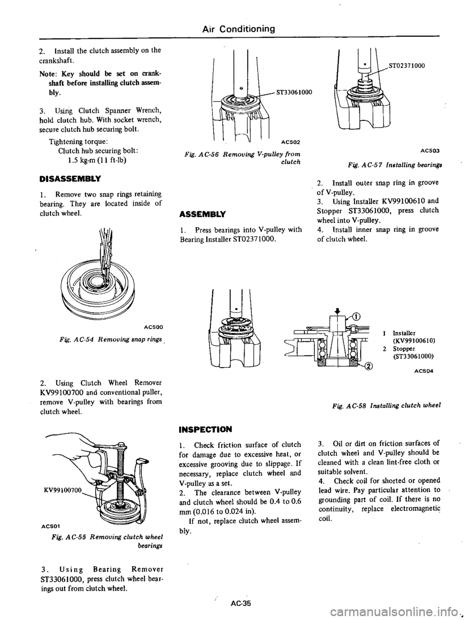
DISASSEMBLY
1
Remove
two
snap
rings
retaining
bearing
They
are
located
inside
of
clutch
wheel
AC500
Fig
AC
54
Removing
snap
rings
2
Using
Clutch
Wheel
Remover
KV99100700
and
conventional
puller
remove
V
pulley
with
bearings
from
clutch
wheel
KV99100700
AC501
Fig
A
C
55
Removing
clutch
wheel
bearings
3
Using
Bearing
Remover
ST33061000
press
clutch
wheel
bear
ings
out
from
clutch
wheel
Air
Conditioning
9
AC502
Fig
AC
56
Removing
V
pulley
from
clutch
ASSEMBLY
I
Press
bearings
into
V
pulley
with
Bearing
Installer
ST02371000
ST02371000
AC503
Fig
A
C
57
Installing
bearin
2
Install
outer
snap
ring
in
groove
of
V
pulley
3
Using
Installer
KV99100610
and
Stopper
ST33061000
press
clutch
wheel
into
V
pulley
4
Install
inner
snap
ring
in
groove
of
clutch
wheel
t
INSPECTION
Check
friction
surface
of
clutch
for
damage
due
to
excessive
heat
or
excessive
grooving
due
to
slippage
If
necessary
replace
clutch
wheel
and
V
pulley
as
a
set
2
The
clearance
between
V
pulley
and
clutch
wheel
should
be
0
4
to
0
6
mm
0
016
to
0
024
in
If
not
replace
clutch
wheel
assem
bly
AC
35
Installer
KV99100610
2
Stopper
ST33061000
AC504
Fig
AC
58
Installing
clutch
wheel
3
Oil
or
dirt
on
friction
surfaces
of
clutch
wheel
and
V
pulley
should
be
cleaned
with
a
clean
lint
free
cloth
or
suitable
solvent
4
Check
coil
for
shorted
or
opened
lead
wire
Pay
particular
attention
to
grounding
part
of
coil
If
there
is
no
continuity
replace
electromagnetic
coil
Page 525 of 537

AC506
Fig
AC
59
Grounding
point
of
coil
5
If
clutch
assembly
must
lie
re
placed
remember
that
break
in
opera
tion
is
necessary
The
break
in
opera
tion
consists
of
engaging
and
disengag
ing
the
clutch
some
tirty
times
SHAFT
SEAL
ASSEMBLY
The
shaft
seal
assembley
of
this
compressor
is
of
a
simplified
design
yet
tight
sealing
and
long
lasting
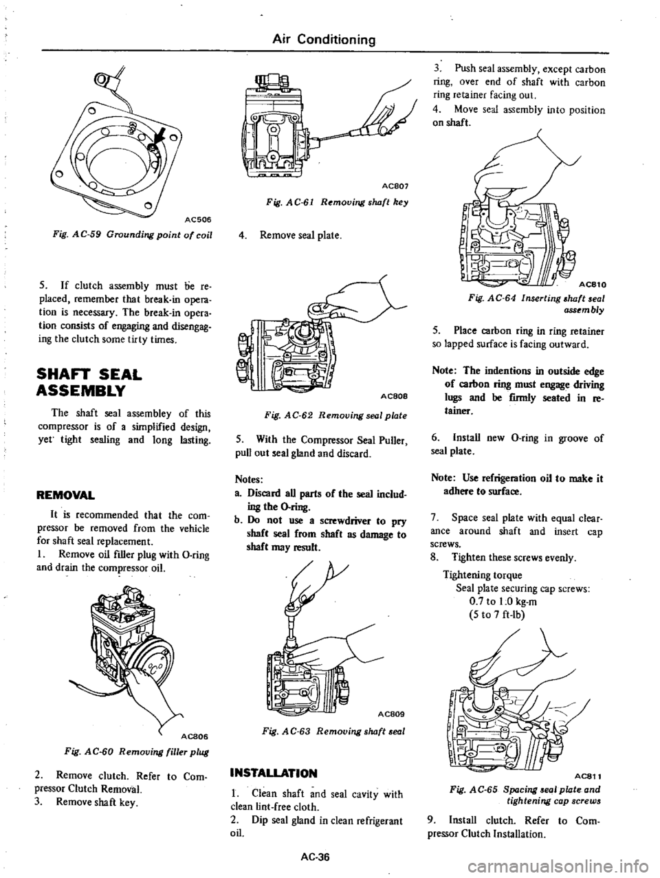
REMOVAL
It
is
recommended
that
the
com
pressor
be
removed
from
the
vehicle
for
shaft
seal
replacement
I
Remove
oil
filler
plug
with
D
ring
and
drain
the
compressor
oil
Fig
AC
60
Removing
filler
plug
2
Remove
clutch
Refer
to
Com
pressor
Clutch
Removal
3
Remove
shaft
key
Air
Conditioning
jpL
Y
L
I
i
0
I
I
0
Ace07
Fig
AC
61
Removing
s
wft
key
4
Remove
seal
plate
AC80e
Fig
AC
62
Removing
seal
plate
5
With
the
Compressor
Seal
Puller
pull
out
seal
gland
and
discard
Notes
a
Discard
all
parts
of
the
seal
includ
ing
the
O
ring
b
Do
not
use
a
screwdriver
to
pry
shaft
seal
from
shaft
as
damage
to
shaft
may
result
AC809
Fig
A
C
63
Removing
s
wft
eal
INSTALLATION
1
Clean
shaft
and
seal
cavity
with
clean
lint
free
cloth
2
Dip
seal
gland
in
clean
refrigerant
oil
AC
36
3
Push
seal
assembly
except
carbon
ring
over
end
of
shaft
with
carbon
ring
retainer
facing
out
4
Move
seal
assembly
into
position
on
shaft
1
I
Fig
AC
64
Inserting
wft
al
ass
mbly
5
Place
carbon
ring
in
ring
retainer
so
lapped
surface
is
facing
outward
Note
The
indentions
in
outside
edge
of
carbon
ring
must
engage
driving
lugs
and
be
firmly
seated
in
re
tainer
6
Install
new
D
ring
in
groove
of
seal
plate
Note
Use
refrigeration
oil
to
make
it
adhere
to
surface
7
Space
seal
plate
with
equal
clear
ance
around
shaft
and
insert
cap
screws
8
Tighten
these
screws
evenly
Tightening
torque
Seal
plate
securing
cap
screws
0
7
to
1
0
kg
m
5
to
7
ft
Ib
AC811
Fig
AC
65
8p
cing
01
plate
and
tightening
cap
screws
9
Install
clutch
Refer
to
Com
pressor
Clutch
Installation