oil pressure DATSUN PICK-UP 1977 Repair Manual
[x] Cancel search | Manufacturer: DATSUN, Model Year: 1977, Model line: PICK-UP, Model: DATSUN PICK-UP 1977Pages: 537, PDF Size: 35.48 MB
Page 321 of 537

Automatic
Transmission
TROUBLE
SHOOTING
GUIDE
FOR
3N71B
AUTOMATIC
TRANSMISSION
Order
Test
item
Checking
Oil
level
gauge
2
Downshift
solenoid
3
Manuallinkage
L
4
Inhibitor
switch
5
Engine
idling
rpm
6
Vacuum
pressure
of
vacuum
pipe
7
Operation
in
each
range
8
Creep
of
vehicle
Stall
test
I
Oil
pressure
before
tesling
1
2
Stall
test
3
Oil
pressure
after
testing
Road
test
Slow
acceleration
I
st
2nd
2nd
3rd
2
Quick
acceleration
lst
2nd
2nd
3rd
3
Kick
down
operation
3rd
2nd
or
2nd
1st
Procedure
Check
gauge
for
oil
level
and
leakage
before
and
after
each
test
Check
for
sound
of
operating
solenoid
when
depressing
accelerator
pedal
fully
with
ignition
key
ON
Check
by
shifting
into
P
lR
IN
D
2
and
I
ranges
with
selector
lever
Check
whether
starter
operates
in
N
and
p
ranges
only
and
whether
reverse
lamp
operates
in
R
range
only
Check
whelher
idling
rpm
meet
standard
Check
whether
vacuum
pressure
is
more
than
450
mmHg
in
idling
and
whether
it
decreases
with
increasing
rpm
Check
whether
transmission
engages
positively
by
shifting
N
0
N
2
N
l
I
and
N
R
range
while
idling
with
brake
applied
Check
whether
there
is
any
creep
in
D
2
R
ranges
and
Measure
line
pressures
in
D
2
I
and
R
range
while
idling
Measure
engine
rpm
and
line
pressure
in
D
2
I
and
R
ranges
during
full
throttle
operati
n
Notes
a
Temperature
of
torque
converter
oil
used
in
test
should
be
from
600
to
1000C
1400
to
2120F
i
e
sufficiently
warmed
up
but
not
overheated
b
To
cool
oil
between
each
stall
test
for
D
2
I
and
R
ranges
idle
engine
i
e
rpm
at
about
1
200
rpm
for
more
than
1
minute
in
P
range
Measurement
time
must
not
be
more
than
5
seconds
Same
as
item
I
Check
vehide
speeds
and
engine
cpm
in
shifting
up
Ist
2nd
range
and
2nd
Jo3rd
range
while
running
with
lever
in
D
range
and
engine
vacuum
pressure
of
about
200
I11I1lHg
Same
as
item
1
above
except
with
engine
vacuum
pressure
of
0
mmHg
i
e
in
position
just
before
kickdown
Check
whether
the
kickdown
operates
and
measure
the
time
delays
while
running
at
30
40
50
60
70
km
h
18
25
30
37
43
MPH
in
D3
range
AT
57
Page 322 of 537
Automatic
Transmission
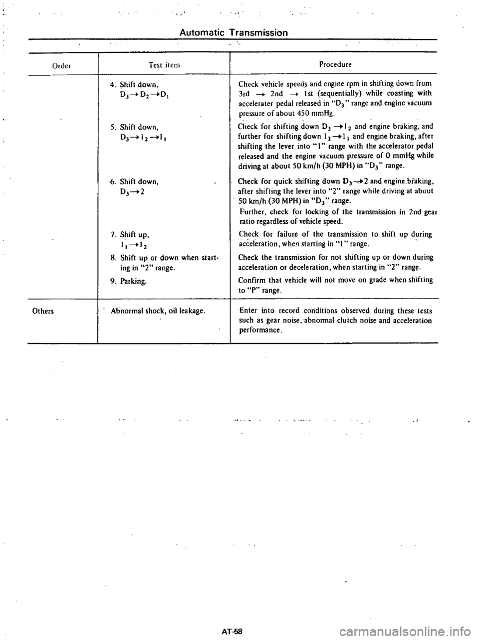
Order
Test
item
4
Shift
down
Dr
O2
0
5
Shift
down
DJ
12
1
6
Shift
down
DJ
2
7
Shift
up
I
12
8
Shift
up
or
down
when
start
iog
in
2
range
9
Parking
Others
Abnormal
shock
oil
leakage
Procedure
Check
vehicle
speeds
and
engine
rpm
in
shifting
down
from
3rd
2nd
I
st
sequentially
while
coasting
with
accelerater
pedal
released
in
D3
range
and
engine
vacuum
pressure
of
about
450
mmHg
Check
for
shifting
down
OJ
12
and
engine
braking
and
further
for
shifting
down
12
I
and
engine
braking
after
shifting
the
lever
into
I
range
with
the
accelerator
pedal
released
and
the
engine
vacuum
pressure
of
0
mmHg
while
driving
at
about
50
km
h
30
MPH
in
OJ
range
Check
for
quick
shifting
down
0
2
and
engine
biaking
after
shifting
the
lever
into
2
range
while
driving
at
about
50
km
h
30
MPH
in
OJ
range
Further
check
for
locking
of
the
transmission
in
2nd
gear
ratio
regardless
of
vehicle
speed
Check
for
failure
of
the
transmission
to
shift
up
during
acceleration
when
starting
in
I
range
Check
the
transmission
for
not
shifting
up
or
down
during
acceleration
or
deceleration
when
starting
in
2
rang
Confirm
that
vehicle
will
not
move
on
grade
when
shifting
to
P
range
Enter
into
record
conditions
observed
during
these
tests
such
as
gear
noise
abnormal
clutch
noise
and
acceleration
performance
AT
58
Page 323 of 537
Automatic
Transmission
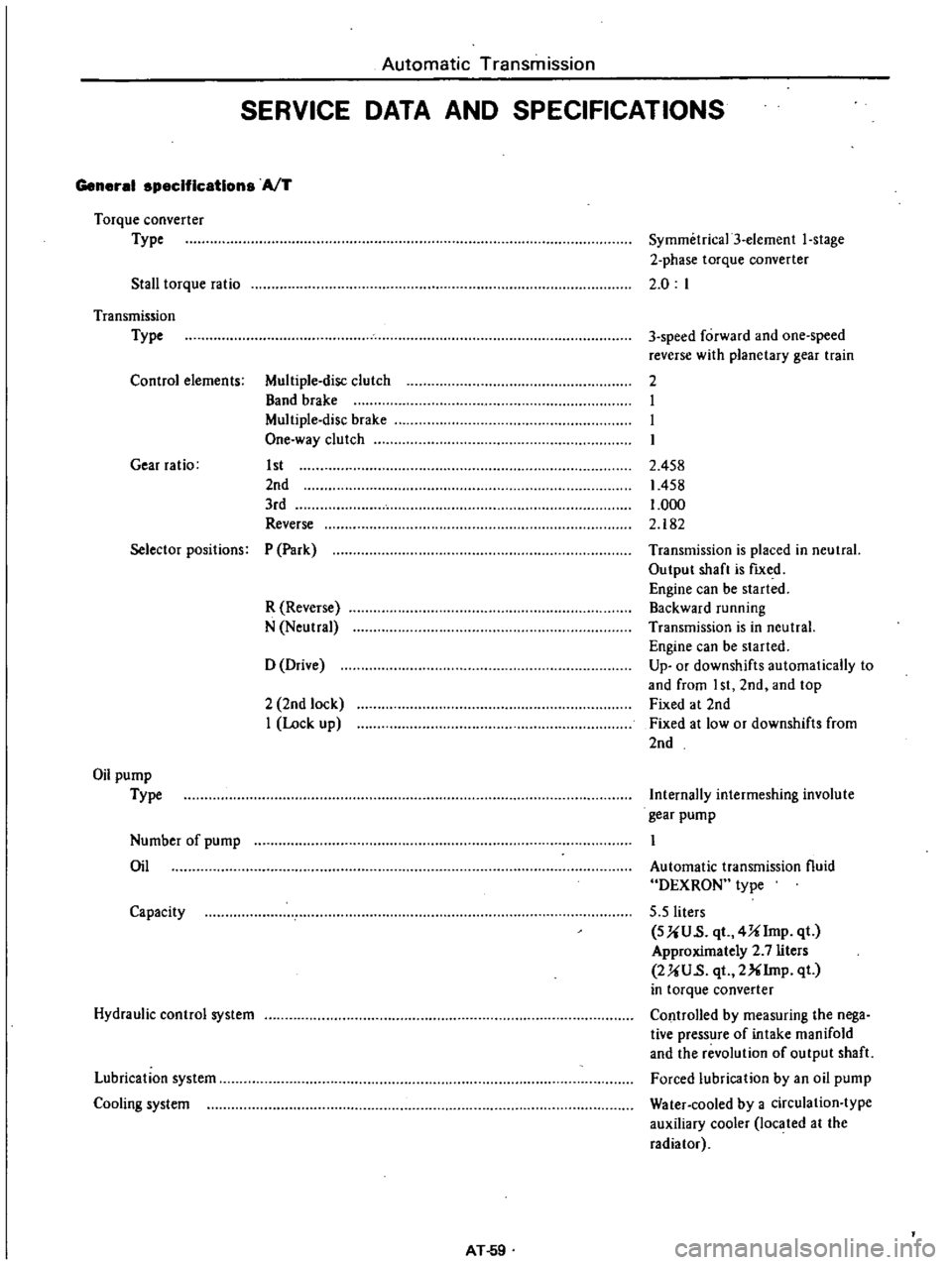
SERVICE
DATA
AND
SPECIFICATIONS
General
specifications
AfT
Torque
converter
Type
Stall
torque
ratio
Symmetrica13
element
I
stage
2
phase
torque
converter
2
0
I
Transmission
Type
Control
elements
Multiple
disc
clutch
Band
brake
Multiple
disc
brake
One
way
clutch
Gear
ratio
1st
2nd
3rd
Reverse
3
speed
forward
and
one
speed
reverse
with
planetary
gear
train
2
I
I
I
2
458
1458
1
000
2
182
Selector
positions
P
Park
R
Reverse
N
Neutral
Transmission
is
placed
in
neutral
Output
shaft
is
fIXed
Engine
can
be
started
Backward
running
Transmission
is
in
neutral
Engine
can
be
started
Up
or
downshifts
automatically
to
and
from
I
st
2nd
and
top
Fixed
at
2nd
Fixed
at
low
or
downshifts
from
2nd
o
Drive
2
2nd
lock
I
Lock
up
Oil
pump
Type
Internally
intermeshing
involute
gear
pump
Number
of
pump
Oil
Automatic
transmission
fluid
DEXRON
type
5
5
liters
SUU
s
qt
4Ulmp
qt
Approximately
2
7
liters
2UU
s
qt
2XIrnp
qt
in
torque
converter
Controlled
by
measuring
the
nega
tive
pressure
of
intake
manifold
and
the
revolution
of
output
shaft
Forced
lubrication
by
an
oil
pump
Water
cooled
by
a
circulation
type
auxiliary
cooler
located
at
the
radiator
Capacity
Hydraulic
control
system
Lubrication
system
Cooling
system
AT
59
Page 325 of 537
Automatic
Transmission
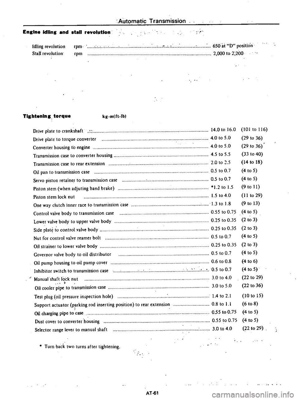
Engine
Idling
and
stall
revolution
Idling
revolution
Stall
revolution
rpm
rpm
6S0
ai
0
position
2
000
to
2
200
TIghtening
torque
kg
m
ft
lb
Drive
plate
to
crankshaft
Drive
plate
to
torque
converter
Converter
housing
to
engine
Transmission
case
to
converter
housing
Transmission
case
to
rear
extension
Oil
pan
to
transmission
case
Servo
piston
retaine
T
to
transmission
case
Pislon
slem
when
adjuting
band
brake
Piston
stem
lock
nut
One
way
clutch
inner
race
to
transmission
case
Control
valve
body
to
transmission
case
Lower
valve
body
to
upper
valve
body
Side
plat
to
control
valve
body
Nut
for
control
valve
reamer
bolt
Oil
strainer
to
lower
valve
body
Governor
valve
body
to
oil
distribu
tor
Oil
pump
housing
to
oil
pump
cover
Inhibitor
switch
to
transmission
case
Manual
shaft
lock
nut
Oil
cooler
pipe
to
transmission
case
Test
plug
oil
pressure
inspection
hole
Support
actuator
parking
rod
inserting
position
to
rear
extension
I
Oil
charging
pipe
to
case
Dust
cover
to
converter
housing
Selector
range
lever
to
manual
shaft
14
0
to
16
0
101
to
116
4
0
to
5
0
29
to
36
4
0
to
S
O
29
10
36
4
S
to
5
5
33
to
40
2
0
to
S
14
to
18
O
S
to
0
7
4
to
S
O
S
to
0
7
4
to
S
1
2
to
1
5
9
to
11
1
5
to
4
0
I
I
to
29
1
3
to
1
8
9
to
13
0
5S
to
0
75
4
to
S
0
25
to
O
3S
2
to
3
0
25
to
0
35
2
to
3
O
S
to
0
7
4
to
S
0
25
to
0
35
2
to
3
D
S
100
7
4
to
5
0
6
to
0
8
4
to
6
0
5
to
0
7
4
toS
3
0
to
4
0
22
to
29
3
0
to
S
O
22
to
36
I
4to
2
1
10
to
IS
0
8
to
I
1
6
to
8
O
5S
to
0
7S
4
to
S
O
5S
to
0
75
4
to
S
3
0
to
4
0
22
to
29
Turn
back
two
turns
after
tightening
AT
61
Page 326 of 537
Automatic
Transmission
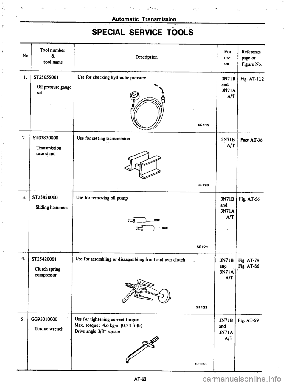
SPECIAL
SERVICE
TOOLS
No
Tool
number
tool
name
Description
For
use
on
Reference
page
or
Figure
No
Oil
pressure
gauge
set
3N71B
Fig
AT
11
2
and
3N71A
AfT
ST2S0SS001
Use
for
checking
hydraulic
pressure
SE119
2
ST07870000
Use
for
setting
transmission
3N71
B
Page
AT
36
AfT
Transmission
case
stand
SE120
3
ST2S850000
Use
for
removing
oil
pump
3N7IB
Fig
AT
S6
and
Sliding
hammers
3N71A
J
AfT
JIB
SE121
4
ST2S42000I
Use
for
assemblilJg
or
disassembling
front
and
rear
clutch
3N71B
Fig
AT
79
and
Fig
AT
86
Clutch
spring
3N7lA
compressor
AIT
SE
122
3N71B
Fig
AT
69
and
3N71A
AlT
Torque
wrench
Use
for
tightening
correct
torque
Max
torque
4
6
kg
m
0
33
ft
lb
Drive
angle
3
8
square
S
GG93010000
SE123
AT
62
Page 356 of 537

Components
Rust
Discoloring
Race
and
roller
u
u
e
2
2
0
3
0
t
c
6
6
6
Fig
h
The
wheel
bearing
is
serv
iceable
if
discoloring
can
be
removed
with
solvent
or
by
polishing
f
a
Inner
race
flaking
t
d
Cracked
roller
iT
t
j
t
11
1
1
t
t
I
l
1
t
F
1ll
JJ
J
t
I
1
ollf
oe
c
g
Recess
on
foDer
Front
Axle
Front
Suspension
Cause
Temperature
increased
during
operation
lowers
when
the
bearing
stops
moisture
inside
the
bearing
is
condensed
becoming
fine
drips
and
the
grease
is
moistened
The
bearing
has
been
placed
in
a
highly
moistened
place
for
a
long
period
of
time
Intrusion
of
moisture
chemicals
etc
or
the
bearing
is
touched
with
bare
hand
and
no
rustproof
action
has
been
taken
Slight
discoloring
may
become
like
oxidized
oil
stain
due
to
grease
In
the
most
cases
this
occurs
when
preliminary
pressure
is
too
high
I
I
I
1
v
i
n
dJ
b
RoUer
flaking
c
Cracked
inner
race
c
f
J
Jt
v
l
e
Recess
on
inner
race
f
Recess
on
outer
race
h
Rust
outer
race
F
A007
Fig
FA
12
Defective
conditions
of
bearing
FA
7
Page 364 of 537
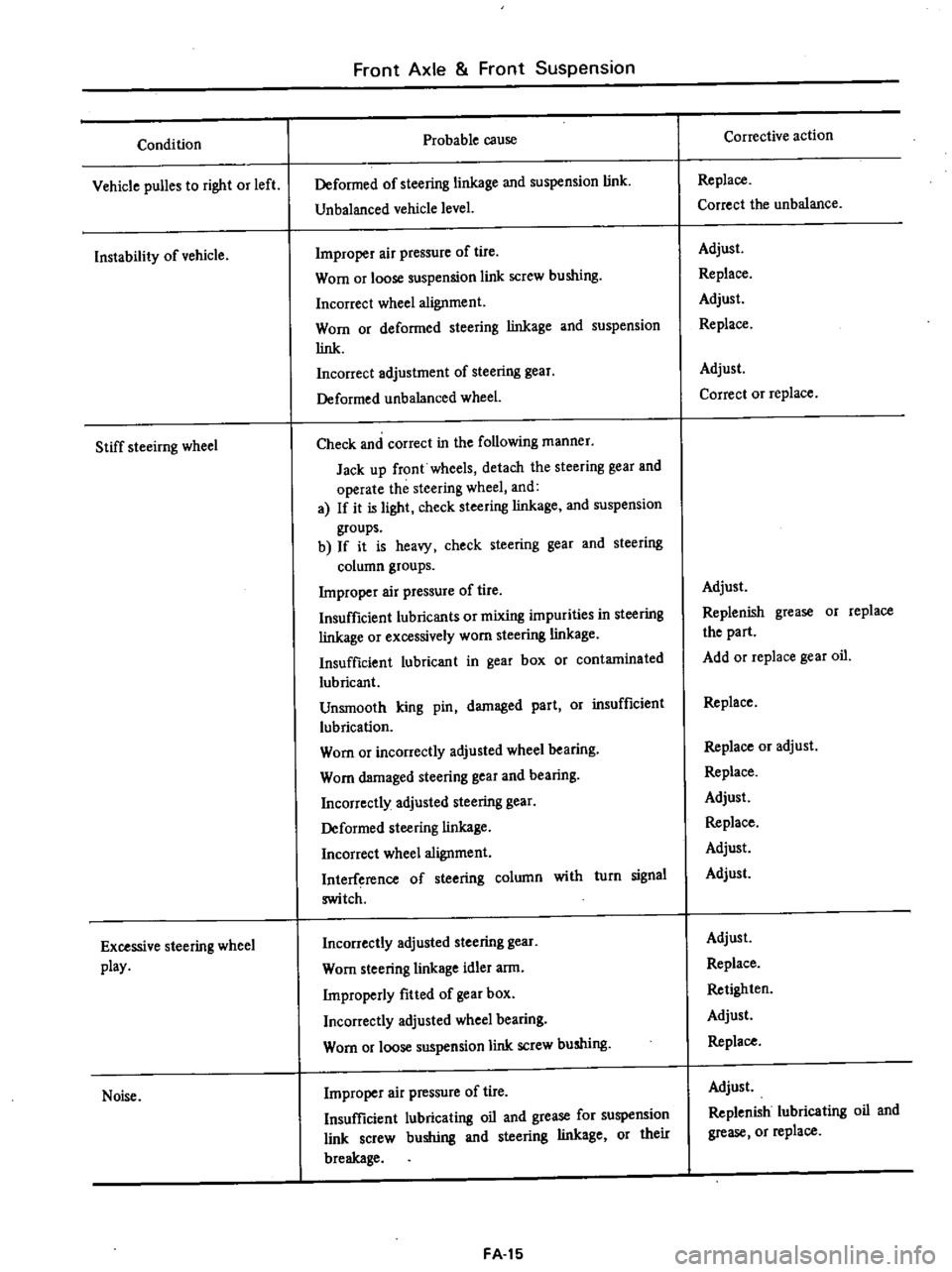
Condition
Vehicle
puBes
to
right
or
left
Instability
of
vehicle
Stiff
steeirng
wheel
Excessive
steering
wheel
play
Noise
Front
Axle
Front
Suspension
Probable
cause
Deformed
of
steering
linkage
and
suspension
link
Unbalanced
vehicle
level
Improper
air
pressure
of
tire
Worn
or
loose
suspension
link
screw
bushing
Incorrect
wheel
alignment
Worn
or
deformed
steering
linkage
and
suspension
link
Incorrect
adjustment
of
steering
gear
Deformed
unbalanced
wheel
Check
and
correct
in
the
following
manner
Jack
up
front
wheels
detach
the
steering
gear
and
operate
the
steering
wheel
and
a
If
it
is
light
check
steering
linkage
and
suspension
groups
b
If
it
is
heavy
check
steering
gear
and
steering
column
groups
Improper
air
pressure
of
tire
Insufficient
lubricants
or
mixing
impurities
in
steering
linkage
or
excessively
worn
steering
linkage
Insufficient
lubricant
in
gear
box
or
contaminated
lubricant
Unsmooth
king
pin
damaged
part
Or
insufficient
lubrication
Worn
or
incorrectly
adjusted
wheel
bearing
Worn
damaged
steering
gear
and
bearing
Incorrectly
adjusted
steering
gear
Deformed
steering
linkage
Incorrect
wheel
alignment
Interference
of
steering
column
with
turn
signal
switch
Incorrectly
adjusted
steering
gear
Worn
steering
linkage
idler
arm
Improperly
fitted
of
gear
box
Incorrectly
adjusted
wheel
bearing
Worn
or
loose
suspension
link
screw
bushing
Improper
air
pressure
of
tire
Insufficient
lubricating
oil
and
grease
for
suspension
link
screw
bushing
and
steering
linkage
or
their
breakage
FA
15
Corrective
action
Replace
Correct
the
unbalance
Adjust
Replace
Adjust
Replace
Adjust
Correct
or
replace
Adjust
Replenish
grease
or
replace
the
part
Add
or
replace
gear
oil
Replace
Replace
or
adjust
Replace
Adjust
Replace
Adjust
Adjust
Adjust
Replace
Retighten
Adjust
Replace
Adjust
Replenish
lubricating
oil
and
grease
or
replace
Page 390 of 537
Probable
cause
I
Air
leakago
at
check
valve
2
Air
leakage
a
t
push
rod
seal
3
Air
leakage
between
valve
body
and
seal
4
Air
leakage
at
valve
plunger
seat
5
Damaged
piping
or
joints
2
Fifteen
seconds
after
engine
is
stopped
and
brake
fully
applied
ob
serve
the
rate
of
drop
in
air
pressure
registered
by
vacuum
gauge
Probable
cause
1
Air
leakage
at
check
valve
2
Damaged
diaphragm
3
Reaction
disc
dropped
off
4
Air
leakage
at
and
valve
body
poppet
assembly
seat
Note
When
replacement
of
any
part
is
required
be
sure
to
renew
Master
Vac
as
an
assembly
Inspecting
check
valve
Remove
clip
and
disconnect
hoses
at
connections
The
check
valve
can
now
be
removed
yr
BA3
Fig
BR
26
Location
of
check
valve
2
Using
a
Master
Vac
tester
apply
a
vacuum
pressure
of
200
mmHg
7
87
inHg
to
the
port
of
check
valve
on
the
Master
Vac
side
If
a
pressure
drop
of
10
mmHg
0
39
inHg
is
exceeded
in
1
I
I
17
I
f
I
I
I
Z
I
I
y1
I
I
I
7
I
I
I
I
I
I
I
I
I
I
y1
II
I
I
I
I
I
I
I
L
I
L
5
to
15
20
25
30
35
40
45
50
55
60
22
44
66
88
110
132
Pedal
operating
force
kg
lb
BR772
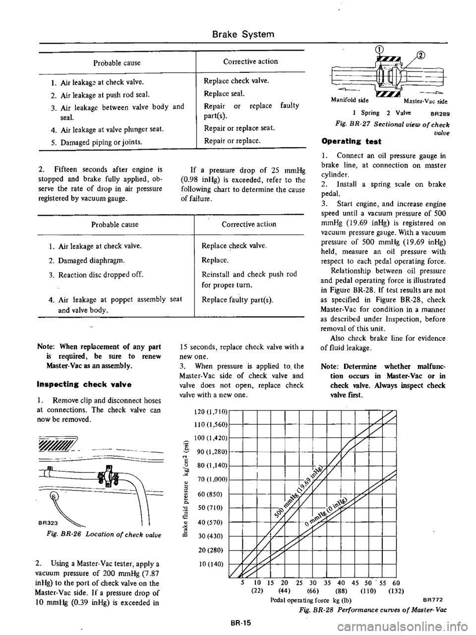
Fig
BR
28
Performance
curves
of
Master
Vac
Brake
System
Corrective
action
Replace
check
valve
Replace
seal
Repair
or
replace
faulty
partes
Repair
or
replace
seat
Repair
or
replace
If
a
pressure
drop
of
25
mmHg
0
98
inHg
is
exceeded
refer
to
the
following
chart
to
determine
the
cause
of
failure
Corrective
action
Replace
check
valve
Replace
Reinstall
and
check
push
rod
for
proper
turn
Replace
faulty
part
s
15
seconds
replace
check
valve
with
a
new
one
3
When
pressure
is
applied
to
the
Master
Vac
side
of
check
valve
and
valve
does
not
open
replace
check
valve
with
a
new
one
120
I
7IG
110
1
560
100
I
420
i
90
1
280
I
u
80
1
140
70
1
000
II
60
850
0
0
5
a
50
710
40
570
30
430
20
280
10
140
BR
15
1
I
Manifold
side
Master
Yac
side
1
Spring
2
Valve
BA289
Fig
BR
27
Sectional
view
of
check
valve
Operating
test
1
Connect
an
oil
pressure
gauge
in
brake
line
at
connection
on
master
cylinder
2
Install
a
spring
scale
on
brake
pedal
3
Start
engine
and
increase
engine
speed
until
a
vacuum
pressure
of
500
mmHg
19
69
inHg
is
registered
on
vacuum
pressure
gauge
With
a
vacuum
pressure
of
500
mmHg
19
69
inHg
held
measure
an
oil
pressure
with
respect
to
each
pedal
operating
force
Relationship
between
oil
pressure
and
pedal
operating
force
is
illustrated
in
Figure
BR
28
If
test
results
are
not
as
specified
in
Figure
BR
28
check
Master
Vac
for
condition
in
a
manner
as
described
under
Inspection
before
removal
of
this
unit
Also
check
brake
line
for
evidence
of
fluid
leakage
Note
Determine
whether
malfunc
tion
occurs
in
Master
Vac
or
in
check
valve
Always
inspect
check
valve
fiTlit
Page 398 of 537

Condition
Brake
chatters
Brake
squeals
Pedal
pulsates
Brakes
fade
Brakes
drag
Unbalanced
brakes
Brake
System
Probable
cause
Groove
or
out
of
round
brake
drum
Loose
or
bent
brake
disc
Distorted
brake
shoes
or
pads
Grease
or
brake
fluid
on
linings
Dirty
or
scored
brake
drums
Distorted
brake
shoes
or
bent
support
plate
Weak
or
broken
brake
shoe
retaining
spring
or
return
spring
Glazed
or
contaminated
brake
lining
Out
of
round
or
off
center
drum
Brake
fluid
has
too
low
boiling
point
Use
of
improper
linings
or
brake
linings
are
contaminated
Brake
drums
are
out
of
round
Hydraulic
connections
master
cylinder
and
wheel
cylinders
are
corroded
or
damaged
Bleed
screw
is
open
Pedal
linkage
is
binding
or
push
rod
adjust
ment
is
too
long
Master
cylinder
compensator
part
is
ob
structed
Seized
master
cylinder
piston
Poor
shoe
condition
Poor
wheel
cylinder
condition
Deformation
of
piston
cups
Hand
brake
will
not
return
Clogged
master
cylinder
return
port
Improper
tire
inflation
Improper
adjustment
of
shoe
to
drum
clear
anee
Grease
oil
mud
or
water
on
linings
or
pads
Mud
in
brake
drum
Deterioration
of
linings
or
pads
Excessive
wear
of
linings
or
pads
BR
23
Corrective
action
Grind
or
replace
as
required
Tighten
support
plate
bolts
to
specified
torque
or
replace
plate
Replace
as
necessary
Replace
linings
Blowout
assembly
with
compressed
air
or
refinish
drum
Replace
faulty
unit
Replace
if
faulty
Cam
ground
lining
to
eliminate
glaze
If
it
doesn
t
replace
linings
Turn
drum
or
replace
as
necessary
Drain
and
fill
system
with
approved
fluid
Replace
linings
Repair
or
replace
as
necessary
Repair
as
necessary
Close
screw
and
bleed
system
Lubricate
linkage
check
pedal
return
spring
for
condition
and
adjust
push
rod
as
neces
sary
Blowout
foreign
matter
with
compressed
air
Disassemble
master
cylinder
and
replace
piston
Bleed
system
Clean
and
repair
Repair
or
replace
Replace
Check
and
repair
Clean
Inflate
to
correct
pressure
Readjust
Clean
brake
mechanism
and
check
for
cause
of
problem
Replace
linings
or
pads
Clean
Replace
Replace
Page 451 of 537
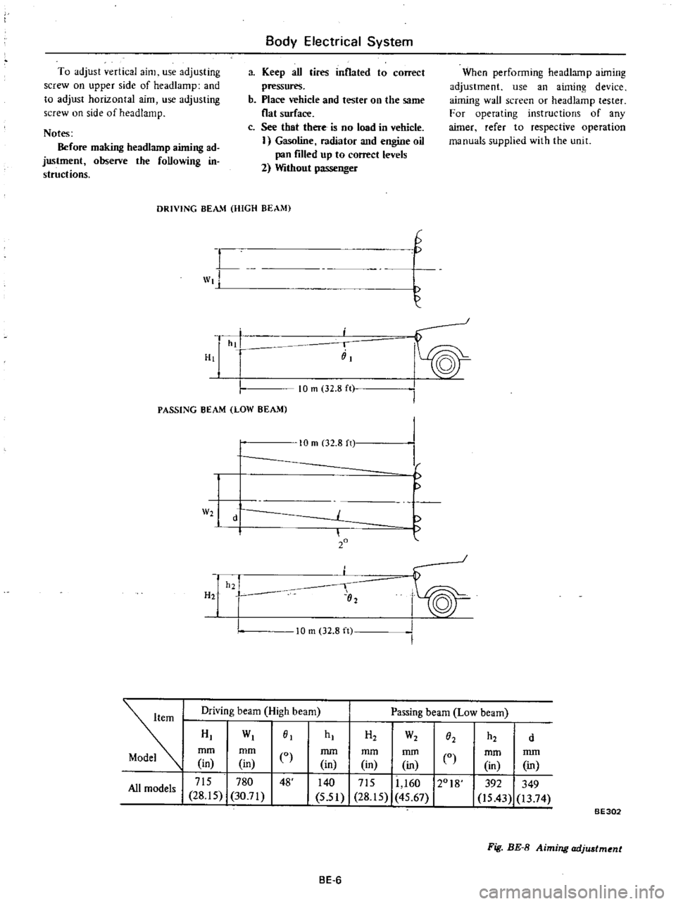
To
adjust
vertical
aim
use
adjusting
screw
on
upper
side
of
headlamp
and
to
adjust
horizontal
aim
use
adjusting
screw
on
side
of
head
lamp
Notes
Before
making
headlarnp
aiming
ad
justment
observe
the
foUowing
in
structions
Body
Electrical
System
a
Keep
aU
tires
inflated
to
correct
pressures
b
Place
vehicle
and
tester
on
the
same
flat
surface
c
See
that
there
is
no
load
in
vehicle
I
Gasoline
radiator
and
engine
oil
pan
filled
up
to
correct
levels
2
Without
passenger
When
performing
headlamp
aiming
adjustment
use
an
aiming
device
aiming
wall
screen
or
headlamp
tester
For
operating
instructions
of
any
aimer
refer
to
respective
operation
manuals
supplied
with
the
unit
DRIVING
BEAM
HIGH
BEAM
L
wt
H
G
hi
i
iiI
PASSING
BEAM
LOW
BEAM
10
m
32
8
ft
W2
H2
10
m
02
8
n
d
20
h2
I
02
I
I
f
10
m
32
8
ft
Driving
beam
High
beam
Passing
beam
Low
beam
HI
WI
01
mm
mm
CO
in
in
I
715
780
48
All
models
28
15
30
71
hI
H2
W2
h2
O2
d
mm
mm
mm
in
in
in
0
140
I
715
11
160
12018
5
51
28
15
45
67
mm
mm
in
in
392
349
is
43
13
74
BE302
Fig
BE
8
Aiming
adjustment
BE
6