check DATSUN PICK-UP 1977 Manual PDF
[x] Cancel search | Manufacturer: DATSUN, Model Year: 1977, Model line: PICK-UP, Model: DATSUN PICK-UP 1977Pages: 537, PDF Size: 35.48 MB
Page 129 of 537
Engine
Fuel
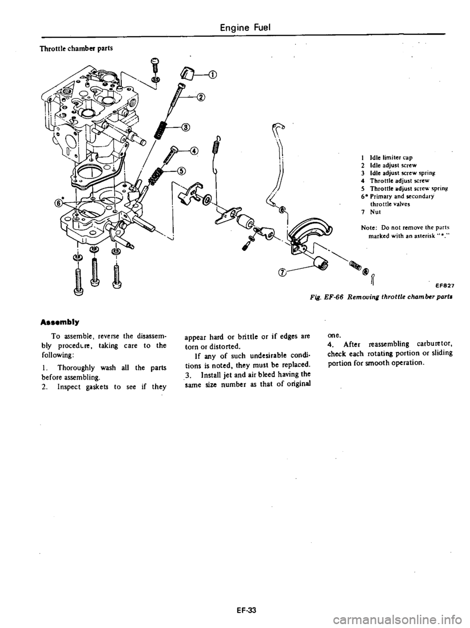
Throttle
chamber
parts
I
Idle
limiter
cap
2
Idle
adjust
screw
3
Idle
adjust
screw
sprinl
4
Throttle
adjust
screw
5
Throttle
adjust
screw
sprini
6
Primary
and
secondary
throttle
valves
7
Nut
Notc
Do
not
remove
the
parlS
marked
with
an
asterisk
@ff
EF827
Fig
EF
66
Removing
throttle
chamlHr
parta
Assembly
To
assemble
reverse
the
disassem
bly
procedcre
taking
care
to
the
following
I
Thoroughly
wash
all
the
parts
before
assembling
2
Inspect
gaskets
to
see
if
they
appear
hard
or
brittle
or
if
edges
are
torn
or
distorted
If
any
of
such
undesirable
condi
tions
is
noted
they
must
be
replaced
3
Install
jet
and
air
bleed
having
the
same
size
number
as
that
of
original
one
4
After
reassembling
carburetor
check
each
rotating
portion
or
sliding
portion
for
smooth
operation
EF
33
Page 130 of 537
CLEANING
AND
INSPECTION
Dirt
gum
wuler
or
l
arbon
con
taminatiun
in
or
on
exterior
moving
parts
of
a
arburctor
arc
often
respon
sihk
for
unsatisfactory
performance
For
this
reason
efficient
carbutetioll
dcpends
upon
careful
cleaning
and
inspection
while
servicing
I
Blow
all
passages
and
castings
with
compressed
air
and
blow
off
all
parts
until
dry
Note
Do
not
pass
drills
or
wires
through
calibrated
jet
or
passaaa
as
this
may
enlarge
orirlce
and
seriously
affect
carburetor
calibrs
lion
2
Check
all
parts
for
wear
If
wear
is
noted
damaged
parts
must
be
re
placed
Note
especially
the
following
Engine
Fuel
I
Check
float
needle
and
seat
for
wear
If
wear
is
noted
assembly
must
be
replaced
2
Check
throule
and
choke
shaft
bores
in
throtlle
chamber
and
choice
chamber
for
wear
or
out
of
roundness
3
Inspect
idle
adjusting
needle
for
burrs
or
ridges
Such
a
condition
re
quires
replacemen
1
3
Inspect
gaskets
0
see
if
they
appear
hard
or
briUle
or
if
edges
are
torn
or
distorted
If
any
such
condi
tion
i
noted
they
must
be
replaced
4
Check
filter
screen
for
dirt
or
lint
Clean
and
if
screen
is
distorted
or
remain
plugged
replace
5
Check
linkage
for
operating
condition
6
Inspect
operation
of
accelerating
pump
Pour
f
el
into
jloat
chamber
and
make
throtlle
lever
operate
Check
condition
of
fuel
injection
from
the
EF
34
accelerating
nowe
7
Push
connecting
rod
of
dia
phragm
chamber
and
block
passage
of
vacuum
with
finger
When
connecting
rod
becomes
free
check
for
leakage
of
air
or
damage
to
diaphragm
Jets
Carburetor
performance
depends
on
jet
and
air
bleed
That
is
why
these
components
must
be
fabricated
with
utmost
care
To
clean
them
use
cleaning
solvent
and
blow
air
on
them
Larger
inner
numbers
tamped
on
the
jet
indicate
larger
diameters
Ac
cordingly
main
and
slow
jets
with
lalger
nUmbers
provide
richer
mixture
the
smaller
the
numbers
the
leaner
the
mixture
Conversely
the
main
and
slow
air
bleeds
through
which
air
to
passes
through
make
the
fueLleaner
if
they
bear
larger
numbers
the
smaller
the
numbers
the
richer
the
fuel
Page 132 of 537
Engine
Fuel
toms
and
causes
of
carburetor
troubles
and
remedies
for
them
are
listed
to
facilitate
quick
repairs
There
are
various
causes
of
engine
malfunctions
It
sometimes
happens
that
a
carburetor
which
has
no
fault
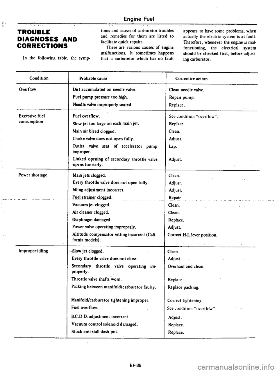
TROUBLE
DIAGNOSES
AND
CORRECTIONS
In
the
following
table
the
syml
Condition
Probable
cause
Overflow
Dirt
accumulated
on
needle
valve
Fuel
pump
pressure
too
high
Needle
valve
improperly
seated
Excessive
fuel
consumption
Fuel
overflow
Slow
jet
too
large
on
each
main
jet
Main
air
bleed
clogged
Choke
valve
does
not
open
fully
Outlet
valve
seat
of
accelerator
pump
improper
Linked
opening
of
secondary
throttle
valve
opens
too
early
Power
shortage
Main
jets
clogged
Every
throttle
valve
does
not
open
fully
Idling
adjustment
incorrect
FIICI
tr
clogged
Vacuum
jet
clogged
Air
c1eane
clogged
Diaphragm
damaged
Power
valve
operating
improperly
Altitude
compensator
setting
incorrect
Cali
fornia
models
Improper
idling
Slow
jet
clogged
Every
throttle
valve
does
not
close
Secondary
throttle
valve
operating
im
properly
Throttle
valve
shafts
worn
Packing
between
manifold
carburetor
fauJiy
Manifold
carburetor
tightening
improper
Fuel
overflow
B
C
D
D
adjustment
incorrect
Vacuum
control
solenoid
damaged
Stuck
anti
stall
dash
pot
EF
36
appears
to
have
some
problems
when
actually
the
electric
system
is
at
fault
Therefore
whenever
the
engine
is
mal
functioning
the
electrical
system
should
be
checked
rust
before
adjust
ing
carburetor
Corrective
action
Clean
needle
valve
Repair
pump
Re
place
See
condition
overflow
Replace
Clean
Adjust
Lap
Adjust
Clean
Adjust
AdjusL
pa
ir
Clean
Clean
Replace
Adjust
Correct
H
L
lever
position
Clean
Adjust
Overhaul
and
clean
Replace
Replace
packing
Correct
tightening
See
l
ondition
ov
rl1ow
Adjust
Replace
Replace
Page 133 of 537
Condition
Engine
hesitation
Engine
does
not
start
Engine
Fuel
Probable
cause
Main
jet
or
slow
jet
clogged
By
pass
hole
idle
passage
dogged
Emulsion
tube
dogged
Idling
adjustment
incorrect
Secondary
throttle
valve
operating
im
properly
Altitude
compensator
setting
incorrect
Cali
fornia
models
Fuel
overflows
No
fuel
Idling
adjustment
incorrect
Fast
idle
adjustment
incorrect
Damaged
anti
dieseling
solenoid
EF
37
Corrective
action
Clean
Clean
tube
Clean
Adjust
Overhaul
and
clean
Correct
H
L
lever
position
See
condition
overflow
Check
pump
fuel
pipe
and
needle
valve
Adjust
Adjust
Replace
Page 135 of 537

There
are
three
types
of
control
system
These
are
J
Closed
type
CIllnkcase
emission
control
system
Emission
Control
System
of
GENERAL
DESCRIPTION
2
Exhaust
emission
control
system
3
Evaporative
ell
lhsion
control
sys
tem
Pericxiic
inspection
and
required
seCV1Clng
of
these
systems
should
be
carried
out
to
reduce
harmful
emis
sions
to
a
minimum
CRANKCASE
EMISSION
CONTROL
SYSTEM
c
01
Lkf
If
1
TIL
II
tll
1
j
GUuuu
DESCRIPTION
This
system
returns
blow
by
gas
to
both
the
intake
manifold
and
carbure
tor
air
cleaner
The
positive
crankcase
ventilation
p
C
V
valve
is
provided
to
conduct
crankcase
blow
by
gas
to
the
intake
manifold
During
partial
throttle
operation
of
the
engine
the
intake
manifold
sucks
the
blow
by
gas
through
the
P
C
V
valve
Normally
the
capacity
of
the
valve
is
sufficient
to
handle
any
blow
by
and
a
small
amount
of
ventilating
air
4
c
Fresh
air
Blow
by
gas
The
ventilating
air
is
then
drawn
from
the
dust
side
of
the
cadlUretor
air
cleaner
tluough
the
tube
con
necting
carburetor
air
cleaner
to
rock
er
cover
into
the
crankcase
Under
full
tluottle
condition
the
manifold
vacuwn
is
insufficient
to
draw
the
blow
by
flow
tluough
the
valve
and
its
flow
goes
through
the
tube
connection
in
the
reverse
diree
tion
On
vehicles
with
an
excessively
high
blow
by
some
of
the
flow
will
go
through
the
tube
connection
to
carbu
retor
air
cleaner
under
all
conditions
1
Sealtypc
oil
level
gauge
2
Bame
plate
3
Flame
arrester
4
Filler
5
P
C
Y
valve
6
Steel
net
7
Bame
plate
EC716
Fig
EC
l
Crankcase
miaion
control
ay
tem
EC
2
INSPECTION
P
c
V
VALVE
AND
FILTER
Checking
P
C
V
valve
in
accord
ance
with
the
following
method
With
engine
running
at
idle
remove
the
ventilator
hose
from
P
C
V
valve
if
the
valve
is
working
a
hissing
noise
will
be
heard
as
air
passes
through
the
valve
and
a
strong
vacuwn
should
be
felt
immediately
when
a
fmger
is
placed
over
valve
inlet
Replace
P
C
V
valve
and
filter
in
accordance
with
the
maintenance
schedule
VENTILATION
HOSE
1
Check
hoses
and
hose
connec
tions
for
leaks
2
Disconnect
all
hoses
and
clean
with
compressed
air
If
any
hose
cannot
be
free
of
obstructions
replace
Ensure
that
flame
arrester
is
surely
inserted
in
hose
between
air
cleaner
and
rocker
cover
Page 137 of 537

Emission
Control
System
IV
7
ID
9
I
Thermal
vacuum
valve
2
Check
valve
3
Air
gallery
pipe
4
Auto
choke
5
Automatic
temperature
control
air
c
canet
6
Anti
Backfire
valve
A
B
valve
7
Boost
Controlled
Deceleration
Device
8
C
D
D
8
P
C
V
valve
9
Air
relief
valve
10
E
G
R
control
valve
11
Air
pump
air
cleaner
12
Carbon
canister
t3
Air
pump
14
Spark
delay
valve
AfT
models
ET365
Fig
EC
2
Exhaust
emission
control
system
Non
California
models
EC
4
Page 138 of 537

Emission
Control
System
5
7
@
@
1
Thermal
acuurn
valve
2
Check
valve
3
Altitude
compcnlator
in
air
cleaner
4
Air
gallery
pipe
5
AutQ
choke
6
Automatic
temperature
control
air
cleaner
1
Anti
8ackfue
valve
A
B
valve
8
Boost
Controlled
Deceleration
DeVice
B
C
D
D
9
P
C
V
valve
10
Air
relief
valve
II
E
G
R
control
valve
12
B
C
D
D
control
valve
and
solenoid
valve
13
Emergency
air
relief
valve
14
Air
pump
air
cleaner
15
Carbon
canister
16
Air
control
yai
e
17
Air
pump
If
ET368
Fig
EC
3
E
hau
t
emilsion
controlay
tem
California
mod
ls
EG
S
Page 140 of 537
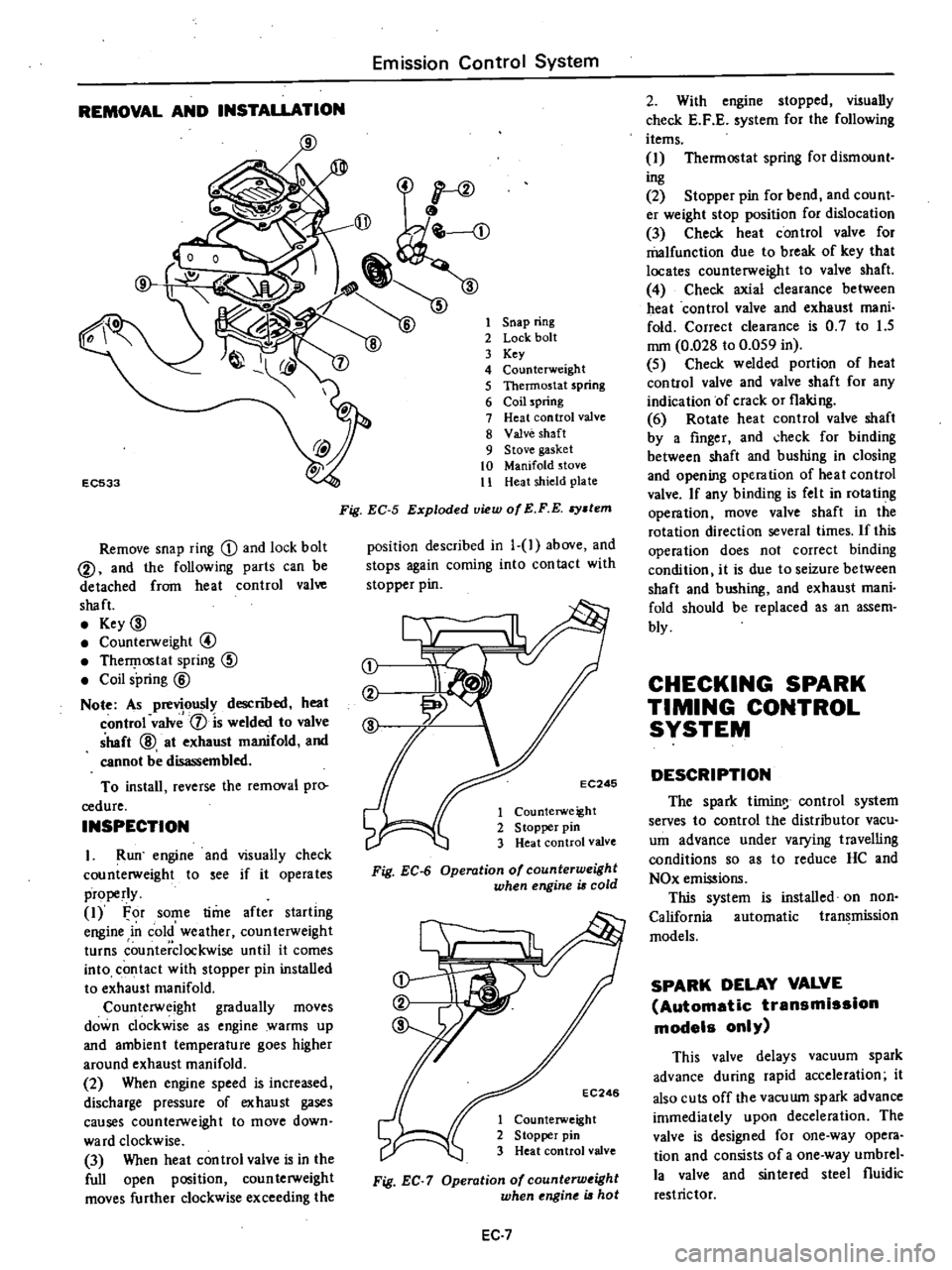
REMOVAL
AND
INSTAUATION
Emission
Control
System
EC533
Remove
snap
ring
D
and
lock
bolt
@
and
the
following
parts
can
be
detached
from
heat
control
valve
shaft
Key
00
Counterweight
@
TherI
lostat
spring
CID
Coil
spring
@
Note
As
previously
descnoed
heat
control
valv
1
is
welded
to
valve
shaft
@
at
exhaust
manifold
and
cannot
be
disassembled
To
install
reverse
the
removal
pro
cedure
INSPECTION
I
Run
engine
and
visually
check
counterweight
to
see
if
it
operates
properly
1
For
some
time
after
starling
engine
in
cold
weather
counterweight
turns
counterclockwise
until
it
comes
into
contact
with
stopper
pin
installed
to
exhaust
manifold
Counterweight
gradually
moves
down
clockwise
as
engine
warms
up
and
ambient
temperature
goes
higher
around
exhaust
manifold
2
When
engine
speed
is
increased
discharge
pressure
of
exhaust
gases
causes
counterweight
to
move
down
ward
clockwise
3
When
heat
con
trol
valve
is
in
the
full
open
position
coun
terweight
moves
further
clockwise
exceeding
the
1
Snap
ring
2
Lock
bolt
3
Key
4
Counterweight
5
Thermostat
spring
6
Coil
spring
7
Heat
control
valve
8
Valve
shaft
9
Stove
gasket
10
Manifold
stove
11
Heat
shield
plate
Fig
EC
5
Exploded
view
of
E
F
E
stem
position
described
in
1
1
above
and
stops
again
coming
into
con
tact
with
stopper
pin
j
EC246
1
Counterweight
2
S
topper
pin
3
Heat
control
valve
Fig
EC
6
Operation
of
counterweight
when
engine
is
cold
EC246
1
Counterweight
2
Stopper
pin
3
Heat
control
valve
Fig
EC
7
Operation
of
counterw
ight
when
ngine
is
hot
EC
7
2
With
engine
stopped
visually
check
E
F
E
system
for
the
following
items
1
Thermostat
spring
for
dismount
ing
2
Stopper
pin
for
bend
and
count
er
weight
stop
position
for
dislocation
3
Check
heat
control
valve
for
malfunction
due
to
break
of
key
that
locates
counterweight
to
valve
shaft
4
Check
axial
clearance
between
heat
control
valve
and
exhaust
mani
fold
Correct
clearance
is
0
7
to
1
5
mm
0
028
to
0
059
in
5
Check
welded
portion
of
heat
control
valve
and
valve
shaft
for
any
indication
of
crack
or
flaking
6
Rotate
heat
control
valve
shaft
by
a
finger
and
check
for
binding
between
shaft
and
bushing
in
closing
and
opening
operation
of
heat
control
valve
If
any
binding
is
felt
in
rotating
operation
move
valve
shaft
in
the
rotation
direction
several
times
If
this
operation
does
not
correct
binding
condition
it
is
due
to
seizure
between
shaft
and
bushing
and
exhaust
mani
fold
should
be
replaced
as
an
assem
bly
CHECKING
SPARK
TIMING
CONTROL
SYSTEM
DESCRIPTION
The
spark
tirnin
control
system
serves
to
control
the
distributor
vacu
um
advance
under
varying
travelling
conditions
so
as
to
reduce
HC
and
NOx
emissions
This
system
is
installed
on
non
California
automatic
transmission
models
SPARK
DELAY
VALVE
Automatic
transmission
models
only
This
valve
delays
vacuum
spark
advance
during
rapid
acceleration
it
also
cuts
off
the
vacuwn
spark
advance
immediately
upon
deceleration
The
valve
is
designed
for
one
way
opera
tion
and
consists
of
a
one
way
umbrel
la
valve
and
sinlered
steel
fluidic
restrictor
Page 141 of 537

Emission
Control
System
C
bur
tor
I
EC284
When
installing
this
valve
ensure
that
it
properly
oriented
Tlus
valve
shuuld
be
replaced
periodically
Refer
to
Maintenance
Schedule
Note
Carburetor
side
Black
DisInDutor
side
Brown
horn
distributor
To
carburetor
TOdi
ribUI0
carburClor
EC
lCiJr
Fig
EC
9
Operation
01
park
delay
value
INSPECTION
Remove
spark
delay
valve
2
Blow
air
through
port
on
carbure
tor
side
then
through
the
other
port
on
distributor
side
Spark
delay
valve
Distributor
side
1
One
way
umbrella
valve
2
Sintered
metal
disc
Fig
EC
8
Spark
delay
valve
is
in
good
condition
if
when
finger
is
placed
over
port
on
distributor
side
air
flow
resistance
is
greater
than
that
on
the
other
side
See
Figur
ET
lO
3
If
a
considerable
air
flow
resist
ance
is
fell
at
port
on
distributor
side
in
step
2
above
and
if
the
condition
of
spark
delay
valve
is
questionable
dip
port
on
carburetor
side
into
a
cup
filled
with
water
Blow
air
through
the
other
port
Small
air
bubbles
should
appear
Carburetor
side
Distributor
side
EC346
Fig
EC
IO
Checking
park
delay
valve
EC
8
EC219
Fig
EC
11
Checking
spark
d
tay
valve
Note
Be
careful
to
avoid
entry
of
oil
or
dirt
into
valve
AIR
INJECTION
SYSTEM
DESCRIPTION
The
Air
Injection
System
A
LS
is
aeSigiieino
iiiject
coin
pressed
air
sec
ODllary
air
corning
from
the
air
pump
into
the
exhaust
manifold
to
reduce
hydrocarbons
and
carbon
monoxide
in
exhaust
lri
s
through
re
combustion
There
are
two
types
of
A
I
S
One
type
is
mounted
on
California
models
and
the
other
is
on
non
California
models
The
non
California
type
con
sists
of
an
air
pump
air
cleaner
an
air
pump
a
relief
valve
a
check
valve
an
anti
backfIre
valve
an
air
gallery
and
hoses
The
California
type
has
in
addition
to
the
components
of
the
non
California
type
an
air
control
valve
and
an
emergency
air
relief
valve
These
valves
prevent
ahnonnal
tem
perature
rise
of
the
catalytic
converter
Page 142 of 537

Emission
Control
System
EC
9
1
Check
valve
2
Air
gallery
pipe
3
Automatic
temperature
control
air
cleaner
4
Air
hose
carburetor
air
cleaner
to
A
B
val
5
Anti
backfire
valve
A
B
valve
6
Air
hose
A
B
valve
to
intake
manifoW
7
Air
hose
carburetor
air
cleaner
to
aU
hose
connector
8
Air
hose
check
valve
to
air
hose
connector
9
3
way
connector
10
Air
hose
air
hose
connector
to
air
pump
11
Air
hose
air
pump
to
air
pump
air
cleaner
12
Air
pump
air
cleaner
13
Air
pump
EC776
Fig
EC
12
Non
California
type
A
I
S
1
Air
control
valve
2
Check
val
3
Air
hose
check
valve
to
air
hose
connector
4
Air
gallery
pipe
5
Automatic
temperature
control
air
cleaner
6
Air
hose
carburetor
air
cleaner
to
A
B
val
7
Anti
backfire
valve
A
B
valve
8
Air
hose
A
B
valve
to
intake
manifold
9
Air
relief
valye
10
Air
hose
carhuIetor
air
cleaner
to
air
control
valve
11
Air
hose
air
relief
valve
to
air
hose
connector
12
Air
hose
air
hose
connector
to
emergency
air
relief
valve
13
Emergency
air
relief
valve
14
Air
pump
air
cleaner
15
Air
hose
air
hose
connector
to
air
pump
16
Air
hose
air
pump
to
air
pump
air
cleaner
17
Air
pump
EC777
Fig
EC
13
California
typo
A
I
S