check DATSUN PICK-UP 1977 Manual Online
[x] Cancel search | Manufacturer: DATSUN, Model Year: 1977, Model line: PICK-UP, Model: DATSUN PICK-UP 1977Pages: 537, PDF Size: 35.48 MB
Page 144 of 537
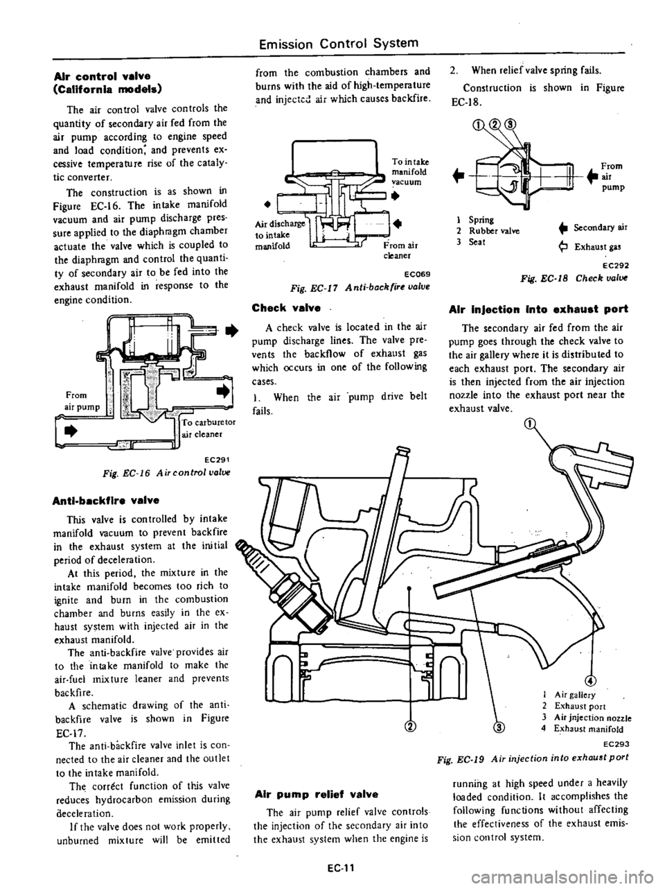
Air
control
valve
CalifornIa
models
The
air
control
valve
con
troIs
the
quantity
of
secondary
air
fed
from
the
air
pump
according
to
engine
speed
and
load
condition
and
prevents
ex
cessive
temperature
rise
of
the
cataly
tic
converter
The
construction
is
as
shown
in
Figure
EC
16
The
intake
manifold
vacuum
and
air
pump
discharge
pres
sure
applied
to
the
diaphragm
chamber
actuate
the
valve
which
is
coupled
to
the
diaphragm
and
control
the
quanti
ty
of
secondary
air
to
be
fed
into
the
exhaust
manifold
in
response
to
the
engine
condition
c
From
air
pump
To
carburetor
air
cleaner
lr
J
EC291
Fig
EC
16
Air
control
valve
Anti
backfire
valve
This
valve
is
con
trolled
by
intake
manifold
vacuum
to
prevent
backfire
in
the
exhaust
system
at
the
ini
tial
period
of
deceleration
At
this
period
the
mixture
in
the
intake
manifold
becomes
too
rich
to
ignite
and
burn
in
the
combustion
chamber
and
burns
easily
in
the
ex
haust
system
with
injected
air
in
the
exhaust
manifold
The
anti
backfire
valve
provides
air
to
the
intake
manifold
to
make
the
air
fuel
mixture
leaner
and
prevents
backfire
A
schematic
drawing
of
the
anti
backfire
valve
is
shown
in
Figure
EC
17
The
anti
backfire
valve
inlet
is
con
nected
to
the
air
cleaner
and
the
outlet
to
the
intake
manifold
Th
correct
function
of
It
jS
valve
reduces
hydrocarbon
emission
during
aeceleration
If
the
valve
does
not
work
properly
unburned
mixture
will
be
emitted
Emission
Control
System
from
the
combustion
chambers
and
burns
with
the
aid
of
high
temperature
and
injected
air
which
causes
backfire
I
Tointake
c
manifold
vacuum
I
L
AirdisChaJ1le
I
to
mtake
manifold
From
air
cleaner
ECQ69
Fig
EC
11
Anti
back
ir
valve
Check
valve
A
check
valve
is
located
in
the
air
pump
discharge
lines
The
valve
pre
ven
ts
the
backflow
of
exhaust
gas
which
occurs
in
one
of
the
following
cases
1
When
the
air
pump
drive
belt
fails
2
When
relief
valve
spring
fails
Construction
is
shown
in
Figure
EC
18
F
rom
m
pump
1
Spring
2
Rubber
valve
3
Seat
Secondary
air
Exhaust
gas
EC292
Fig
EC
1B
Check
valve
AIr
InJaction
Into
axhaust
port
The
secondary
air
fed
from
the
air
pump
goes
through
the
check
valve
to
the
air
gallery
where
it
is
distributed
to
each
exhaust
port
The
secondary
air
is
then
injected
from
the
air
injection
nozzle
into
the
exhaust
port
near
the
exhaust
valve
n
L
y
r
V
Air
pump
relief
valve
The
air
pump
relief
valve
controls
the
injection
of
the
secondary
air
into
the
exhaust
system
when
the
engine
is
EG
11
3
I
Air
gallery
2
Exhaust
port
3
Air
jnjection
nozzle
4
Exhaust
manifold
EC293
Fig
EC
19
Air
injection
into
exhaust
port
running
at
high
speed
under
a
heavily
loaded
condition
It
accomplishes
the
following
functions
without
affecting
the
effectiveness
of
the
exhaust
emis
sion
control
system
Page 145 of 537
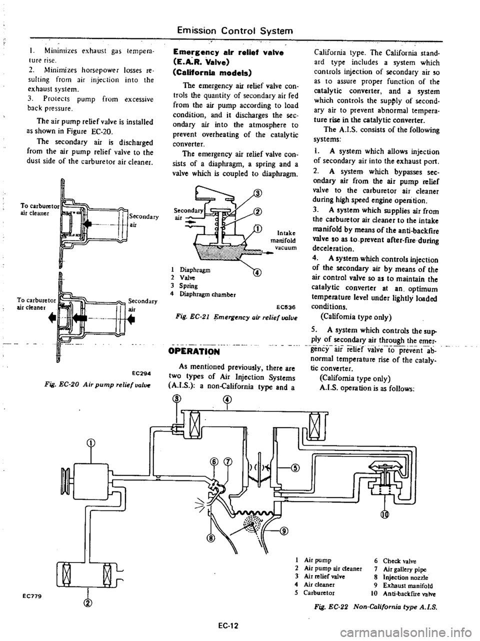
Minimizes
exhaust
gas
tempera
lure
rise
2
Minimizes
horsepower
losses
re
suiting
from
air
injection
into
the
exhaust
system
3
Protects
pump
from
excessive
back
pressure
The
air
pump
relief
valve
is
installed
as
shown
in
Figure
EC
20
The
secondary
air
is
discharged
from
the
air
pump
relief
valve
to
the
dust
side
of
the
carburetor
air
cleaner
To
carburetor
air
cleaner
Secondary
air
To
carburetor
air
cleaner
J
erCOndary
r
r
EC294
Fig
EC
20
Air
pump
relief
valve
Emission
Control
System
Emargency
air
retial
valve
E
A
R
Valve
California
models
The
emergency
air
relief
valve
con
trols
the
quantity
of
secondary
air
fed
from
the
air
pump
according
to
load
condition
and
it
discharges
the
see
ondary
air
into
the
atmosphere
to
prevent
overheating
of
the
catalytic
converter
The
emergency
air
relief
valve
con
sists
of
a
diaphragm
a
spring
and
a
valve
which
is
coupled
to
diaphragm
1
Diaphragm
2
Val
3
Spring
4
Diaphragm
chamber
EC536
Fig
EC
21
mergency
air
relief
valve
OPERATION
As
mentioned
previously
there
are
two
types
of
Air
Injection
Systems
A
I
S
a
non
California
type
and
a
California
type
The
California
stand
ard
type
includes
a
system
which
controls
injection
of
secondary
air
so
as
to
assure
proper
function
of
the
catalytic
converter
and
a
system
which
controls
the
supply
of
second
ary
air
to
prevent
abnormal
tempera
tUfe
rise
in
the
catalytic
converter
The
A
I
S
consists
of
the
following
systems
L
A
system
which
allows
injection
of
secondary
air
into
the
exhaust
port
2
A
system
which
bypasses
sec
ondary
air
from
the
air
pump
relief
valve
to
the
carburetor
air
cleaner
during
high
speed
engine
operation
3
A
system
which
supplies
air
from
the
carburetor
air
cleaner
to
the
intake
manifold
by
means
of
the
anti
backfire
valve
so
as
to
prevent
after
fire
during
deceleration
4
A
system
which
controls
injection
of
the
secondary
air
by
means
of
the
air
control
valve
so
as
to
maintain
the
catalytic
converter
at
an
optimum
temperature
level
under
lightly
loaded
condi
tions
Califomia
type
only
5
A
system
which
controls
the
sup
ply
of
secondary
air
through
the
emer
gency
air
relief
vilve
io
pfevent
ab
normal
temperature
rise
of
the
cataly
tic
converter
California
type
only
A
I
S
operation
is
as
follows
I
I
t
1
r
9
I
Air
pump
6
Check
valve
I
0
L
2
Air
pump
air
deaner
7
Air
gallery
pipe
3
Air
relief
valve
8
Injection
non
e
r
4
Air
cleaner
9
Exhaust
manifold
5
Carburetor
10
Anti
backflIe
valve
EC179
Fig
EC
22
Non
California
type
A
I
S
EC
12
Page 146 of 537
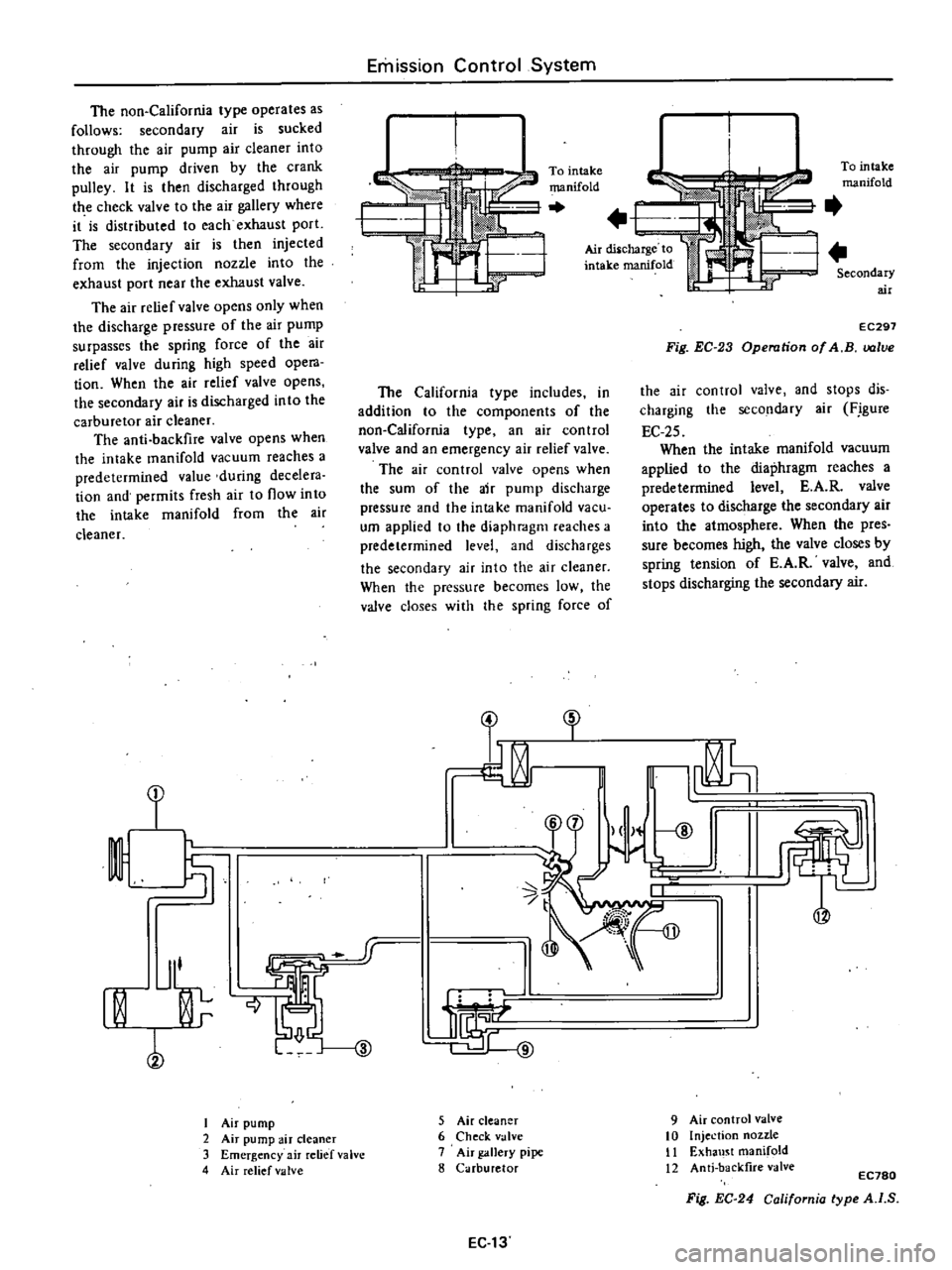
The
non
California
type
operates
as
follows
secondary
air
is
sucked
through
the
air
pump
air
cleaner
into
the
air
pump
driven
by
the
crank
pulley
It
is
then
discharged
through
the
check
valve
to
the
air
gallety
where
it
is
distributed
to
each
exhaust
porL
The
secondary
air
is
then
injected
from
the
injection
nozzle
into
the
exhaust
port
near
the
exhaust
valve
The
air
relief
valve
opens
only
when
the
discharge
pressure
of
the
air
pump
surpasses
the
spring
force
of
the
air
relief
valve
during
high
speed
opera
tion
When
the
air
relief
valve
opens
the
secondary
air
is
discharged
in
to
the
carburetor
air
c1eaner
The
anti
backfire
valve
opens
when
the
intake
manifold
vacuum
reaches
a
predetermined
value
during
decelera
tion
and
permits
fresh
air
to
now
into
the
intake
manifold
from
the
air
cleaner
f
I
Jl
rn
l
I
Air
pump
2
Air
pump
air
cleaner
3
Emergency
air
relief
valve
4
Air
relief
valve
riu
Qj
j
I
@
Emission
Control
System
To
intake
manifold
The
California
type
includes
in
addition
to
the
components
of
the
non
California
type
an
air
control
valve
and
an
emergency
air
relief
valve
The
air
control
valve
opens
when
the
sum
of
the
air
pump
discharge
pressure
and
the
intake
manifold
vacu
um
applied
to
the
diaphmgm
reaches
a
predetermined
level
and
discharges
the
secondary
air
into
the
air
cleaner
When
the
pressure
becomes
low
the
valve
doses
with
the
spring
force
of
3
5
Air
cleaner
6
Check
valve
7
Air
gallery
pipe
8
Carburetor
EC
13
To
intake
manifold
Air
diSlcharge
to
intake
manifold
Secondary
air
EC297
Fig
EC
23
Operation
of
A
B
lve
the
air
control
valve
and
stops
dis
charging
the
secondary
air
F
igure
EC
25
When
the
intake
manifold
vacuum
applied
to
the
diaphragm
reaches
a
predetermined
level
E
A
R
valve
operates
to
discharge
the
secondary
air
into
the
atmosphere
When
the
pres
sure
becomes
high
the
valve
closes
by
spring
tension
of
E
A
R
valve
and
stops
discharging
the
secondary
air
fl
t
9
Air
control
valve
10
Injection
nozzle
II
Exha
l
t
manifold
12
Anti
backfire
valve
EC780
Fig
EC
24
California
type
A
I
S
Page 147 of 537

9
From
air
pump
l
h
1
Not
actuated
REMOVAL
AND
INSTALLATION
Air
p
mp
sir
cleaner
Remove
air
hose
then
detach
air
cleaner
from
hoodledge
Air
cleaner
element
and
Ii
r
deancr
lower
body
are
built
into
a
unit
construction
Replace
air
cleaner
clcl
nen
and
lower
body
as
an
assembly
J
J
tt
c
t
o
J
EC
323
Fig
EC
26
Replacing
oir
cleaner
element
Air
pum
Remove
air
hoses
from
air
pump
2
Loosen
air
pump
adjusting
bar
mounting
bolts
and
air
pump
mount
ing
bolts
then
remove
air
pump
drive
bell
3
Remove
air
pump
pulley
4
Remove
air
pump
from
bracket
Air
control
valve
California
models
l
Disconnect
air
hoses
and
a
vacu
um
hose
from
air
control
valve
2
Remove
air
con
trol
valve
from
bracket
E
A
R
valve
California
modela
Remove
vacuum
pipe
and
air
hose
and
dismount
E
A
R
valve
Emission
Control
System
o
jJ
To
Intake
mamfold
rF
vacuum
r
To
air
cleaner
From
air
pump
EC781
Fig
EC
27
Locotion
of
E
A
R
wive
Antl
backflravalve
Disconnect
air
hose
and
vacuum
hose
from
anti
backfire
valve
Check
valve
Disconnect
hose
and
remove
check
valve
from
air
gallery
pipe
Air
ganery
pIpe
andinJactlon
nozzles
It
is
very
difficult
to
remove
the
air
gallery
from
the
exhaust
manifold
without
bending
the
pipe
which
could
result
in
fractures
or
leakage
There
fore
removal
of
the
air
gallery
pipe
and
injection
nozzles
should
be
under
taken
only
when
they
are
damaged
I
Lubricate
around
the
connecting
portion
of
air
injection
nozzle
and
air
gallery
with
engine
oil
2
Hold
air
injection
nozzle
hexagon
head
with
a
wrench
and
unfasten
flare
screw
connecting
ait
gallery
to
injec
tion
nozzle
Remove
air
gallery
EC
14
To
intake
manifold
vaCUl
lm
r
Y
4
9
Gf
T
I
To
air
cleaner
I
Actuated
EC299
Fig
EC
25
Operation
of
air
control
value
Notes
a
Apply
engine
011
to
rews
several
times
during
above
work
b
Be
atreful
not
to
damage
other
parts
3
Unfasten
air
injection
nozzle
from
cylinder
head
applying
engine
oil
to
screwed
portion
several
times
4
Check
air
gallery
and
nozzle
for
fractures
or
leakage
Clean
air
injection
nozzle
with
a
wire
brush
5
At
time
of
installation
hold
air
injection
nozzle
hexagon
head
with
a
wrench
and
tighten
air
gallery
flange
screw
to
a
torque
of
5
0
to
5
9
kg
m
36
to
43
ft
lb
6
Check
cylinder
head
air
injection
nozzle
and
air
gallery
for
leaks
with
engine
running
Air
pump
relief
vslve
Loosen
carburetor
air
cleaner
mounting
sc
ews
and
remove
air
pump
relief
valve
InstallatIon
Install
in
the
reverse
order
of
reo
moval
DISASSEMBLY
AND
ASSEMBLY
Disassembly
of
air
pump
1
Remove
four
pulley
drive
bolts
and
remove
pulley
from
hub
2
Secure
air
pump
drive
hub
in
a
vise
as
shewn
in
Figure
EC
28
and
remove
four
end
cover
bolts
Page 150 of 537
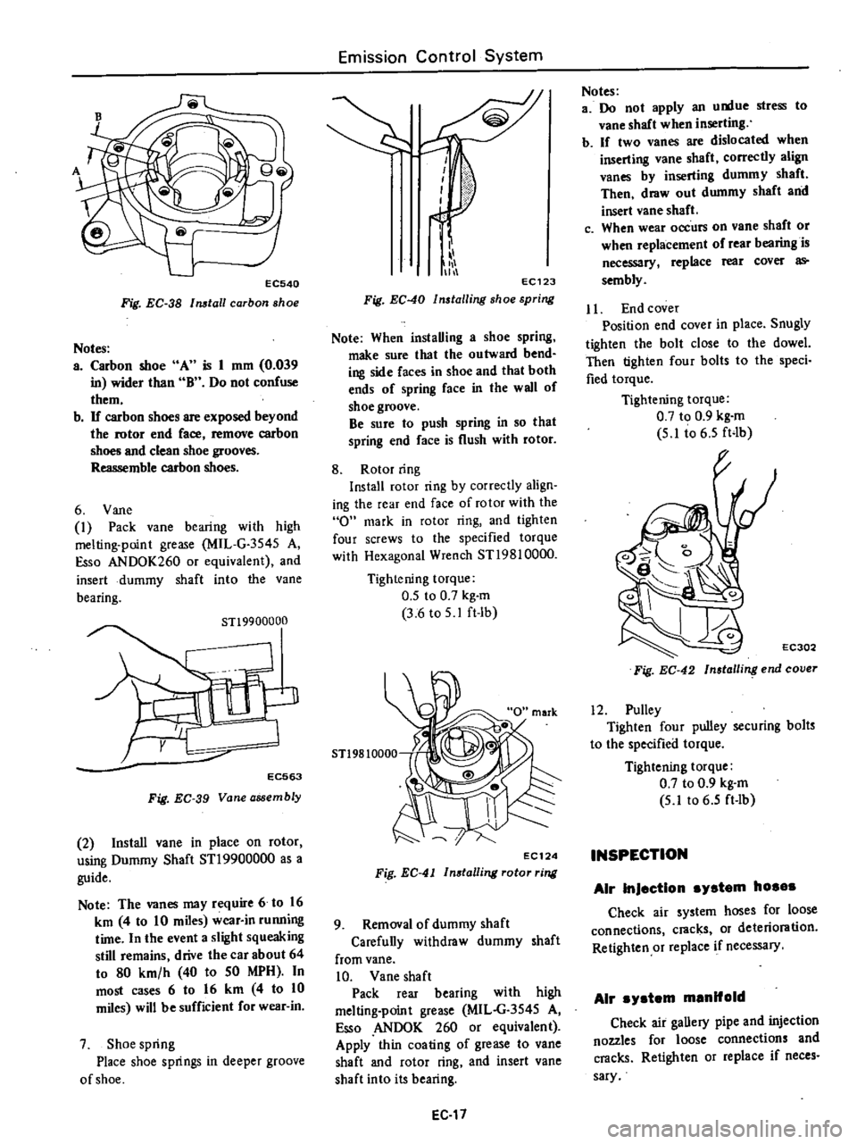
EC540
Fig
EC
38
Install
carbon
shoe
Notes
a
Carbon
shoe
A
is
1
mm
0
039
in
wider
than
B
Do
not
confuse
them
b
If
carbon
shoes
are
exposed
beyond
the
rotor
end
face
remove
carbon
shoes
and
clean
shoe
grooves
Reassemble
carbon
shoes
6
Vane
1
Pack
vane
bearing
with
high
melting
point
grease
MIL
G
3545
A
Esso
ANDOK260
or
equivalent
and
insert
dummy
shaft
into
the
Vane
bearing
STl9900000
EC563
Fig
EC
39
Vane
assembly
2
Install
vane
in
place
on
rotor
using
Dummy
Shaft
STl9900000
as
a
guide
Note
The
vanes
may
require
6
to
16
km
4
to
10
miles
wear
in
running
time
In
the
event
a
slight
squeaking
still
remains
drive
the
car
about
64
to
80
km
h
40
to
50
MPH
In
most
cases
6
to
16
km
4
to
10
miles
will
be
sufficient
for
wear
in
7
Shoe
spring
Place
shoe
springs
in
deeper
groove
of
shoe
Emission
Control
System
i
111
11
EC123
Fig
EC
40
Installing
shoe
spring
Note
When
instaUing
a
shoe
spring
make
sure
that
the
outward
bend
ing
side
faces
in
shoe
and
that
both
ends
of
spring
face
in
the
wall
of
shoe
groove
Be
sure
to
push
spring
in
so
that
spring
end
face
is
flush
with
rotor
8
Rotor
ring
Install
rotor
ring
by
correctly
align
ing
the
rear
end
face
of
rotor
with
the
0
mark
in
rotor
ring
and
tighten
four
screws
to
the
specified
torque
with
Hexagonal
Wrench
ST19810000
Tightening
torque
0
5
to
0
7
kg
m
3
6
to
5
1
ft
lb
5T19810000
EC124
Fig
EC
41
In8talling
rotor
ring
9
Removal
of
dummy
shaft
Carefuny
withdraw
dummy
shaft
from
vane
10
Vane
shaft
Pack
rear
bearing
with
high
melting
point
grease
MIL
G
3545
A
so
ANDOK
260
or
equivalent
Apply
thin
coating
of
grease
to
vane
shaft
and
rotor
ring
and
insert
vane
shaft
into
its
bearing
EC
17
Notes
a
Do
not
apply
an
u
tue
stress
to
vane
shaft
when
inserting
b
If
two
vanes
are
dislocated
when
inserting
vane
shaft
correctly
align
vanes
by
inserting
dummy
shaft
Then
draw
out
dummy
shaft
and
insert
vane
shaft
c
When
wear
occurs
on
vane
shaft
or
when
replacement
of
rear
bearing
is
necessary
replace
rear
cover
as
sembly
Jl
End
cover
Position
end
cover
in
place
Snugly
tighten
the
bolt
close
to
the
dowel
Then
tighten
four
bolts
to
the
speci
fied
torque
Tightening
torque
0
7
to
0
9
kg
m
5
1
t06
5
ft4b
EC302
Fig
EC
42
Insla
ling
end
cover
12
Pulley
Tighten
four
pulley
securing
bolts
to
the
specified
torque
Tightening
torque
0
7
to
0
9
kg
m
5
lt06
5
ft
lb
INSPECTION
Air
InJection
system
hosas
Check
air
system
hoses
for
loose
connections
cracks
or
deterioration
Retighten
or
replace
if
necessary
Air
ystem
manifold
Check
air
gaUery
pipe
and
injection
nozzles
for
loose
connections
and
cracks
Retighten
or
replace
if
neces
sary
Page 151 of 537

Air
pump
I
Operate
engine
until
it
reaches
normal
operating
temperature
2
Inspect
all
hose
hose
connec
tions
and
air
gallery
for
leaks
and
correct
if
necessary
before
checking
air
injection
pump
3
Check
air
injection
pump
belt
tension
and
adjust
to
specifications
if
necessary
4
Disconnect
air
supply
hose
at
check
valve
5
Disconnect
vacuum
hose
from
the
air
control
valve
California
type
only
6
Insert
open
pipe
end
of
Air
Pump
Test
Gauge
Adapter
STl9870000
in
air
supply
hose
Clamp
hose
securely
to
adapter
to
prevent
it
from
blowing
out
Position
adapter
and
test
lli
uge
so
that
air
blast
emitted
through
drilled
pipe
plug
will
be
harmlessly
dissipated
7
Install
a
tachometer
on
engine
With
engine
speed
at
2
600
rpm
ob
serve
pressure
produced
at
test
gauge
Air
pressure
should
be
100
mmHg
3
94
inHg
or
more
8
If
air
pressure
does
not
meet
above
specifications
proceed
as
fol
lows
I
Repeat
2
and
3
above
2
Disconnect
air
supply
hose
at
anti
backfire
valve
Plug
air
hose
open
ing
and
screw
with
a
clamp
Repeat
pressure
test
3
With
engine
speed
at
1
500
rpm
close
hole
of
test
gauge
with
finger
If
a
leaking
sound
is
heard
or
leaking
air
is
felt
by
ftnger
at
relief
valve
relief
valve
is
malfunctioning
Relief
valve
should
be
replaced
or
repaired
4
If
air
injection
pump
does
not
meet
minimum
requirement
of
pres
sure
test
it
should
be
replaced
Control
valve
The
following
procedures
are
reo
commended
for
checking
and
or
as
certaining
that
the
various
components
of
the
exhaust
emission
con
Irol
system
are
operating
properly
The
engine
and
all
components
must
be
at
normal
operating
tempera
tures
when
the
tests
are
performed
Prior
to
performing
any
extensive
diag
nosis
of
the
exhaust
control
system
it
Emission
Control
System
must
be
determined
that
the
engine
as
a
unit
is
functioning
properly
Check
valva
Warm
up
engine
thoroughly
2
Disconnect
hose
leading
to
check
valve
from
air
hose
COJUlector
3
Check
hose
opening
for
any
indi
cation
of
exhaust
gas
leaks
Ifleaks
are
detected
replace
check
valve
4
Race
the
engine
lightly
at
about
2
000
cpm
and
then
return
it
to
idling
VisuaDy
check
the
hose
for
any
indication
of
exhaust
gas
leaks
before
the
engine
returns
to
idling
speed
If
leaks
are
detected
replace
check
valve
EC310
Fig
EC
43
Checking
check
valve
Air
pump
raIle
valve
After
completing
inspection
of
air
pump
check
air
pump
relief
valve
in
the
following
steps
J
Disconnect
hoses
leading
to
check
valve
and
air
control
valve
from
air
hose
connector
and
install
blind
cap
to
the
connector
2
With
engine
running
at
about
3
000
rpm
under
no
load
place
your
hand
on
the
air
outlet
of
air
pump
relief
valve
to
check
for
discharged
air
If
no
air
is
felt
replace
the
air
pump
relief
valve
EC311
Fig
EC
44
Checking
air
pump
relief
valve
EC
18
Air
control
valve
C
U
ornla
models
I
Warm
up
engine
thoroughly
2
Before
checking
air
control
valve
check
all
hoses
for
loose
connection
leaks
etc
and
repair
or
correct
if
necessary
3
With
engine
idling
disconnect
the
outlet
side
hose
of
the
air
control
valve
and
place
your
hand
on
the
air
hose
outlet
to
check
for
air
If
no
air
is
felt
replace
the
air
control
valve
4
Pull
vacuum
hose
off
from
air
con
trol
valve
If
discharge
of
air
from
air
hose
stops
the
air
con
trol
valve
is
normaL
If
discharge
is
still
felt
replace
the
valve
Plug
up
the
removed
vacuum
hose
to
stabilize
engine
running
EC312
Fig
EC
45
Checking
air
control
valve
Emarsancy
air
rella
valve
E
A
R
Valve
lCalHornla
models
L
Warm
up
engine
thoroughly
2
Before
checking
air
control
valve
check
all
hoses
for
loose
connection
leaks
etc
and
repair
or
correct
if
necessary
3
Race
engine
approximately
2
000
rpm
under
no
load
Place
your
hand
on
air
outlet
of
E
A
R
valve
to
check
for
presence
of
discharged
air
If
no
air
is
felt
E
A
R
valve
is
normal
4
Disconnect
vacuum
hose
from
B
A
R
valve
as
shown
in
Figure
EC
46
Page 152 of 537

Race
engine
approximately
2
000
rpm
under
no
load
Place
your
hand
on
air
outlet
of
E
A
R
valve
to
check
for
presence
of
discharged
air
If
air
is
felt
E
A
R
valve
is
normaL
5
If
E
A
R
valve
does
not
function
properly
at
above
steps
replace
E
A
R
valve
To
air
pump
I
ET267
Fig
EC
46
Cheeking
E
A
R
volve
Anti
backfire
valve
A
valve
Warm
up
engine
thoroughly
2
Disconnect
hose
from
air
cleaner
and
place
a
finger
near
the
outlet
3
Run
engine
at
about
3
000
rpin
under
no
load
then
quickly
cetum
it
to
idling
If
you
feel
a
pull
or
suction
force
on
your
finger
the
anti
backfire
valve
is
functioning
normally
If
no
suction
is
felt
replace
the
anti
backflre
valve
Fig
EC
47
Checking
anti
backfire
valve
1
t
D
I
Y1
VI
I
ID
4
JO
0
2
E
C
R
control
valve
3
E
C
R
passage
4
Intake
manifold
5
Thermal
vacuum
valve
6
E
C
R
tube
7
Exhaust
manifold
Emission
Control
System
tXHAUST
GAS
RECIRCULATION
CONTROL
SYSTEM
E
G
R
DESCRIPTION
In
the
exhaust
gas
recirculation
system
a
part
of
the
exhaust
gas
is
returned
to
the
combustion
chamber
to
lower
the
spark
flame
temperature
during
combustion
This
results
in
a
reduction
of
the
nitrogen
oxide
con
ten
t
in
the
exhaust
gas
The
exhaust
gas
recirculation
sys
tem
consists
of
an
E
G
R
passage
E
G
R
con
trol
valve
thermal
vacuum
volve
E
G
R
tube
and
hose
A
warn
@
I
ing
system
which
indicates
when
the
E
G
R
control
system
must
be
in
spected
is
also
installed
in
all
620
models
except
those
bound
for
Coli
fornia
and
Canada
When
the
E
G
R
con
trol
valve
is
open
some
of
the
exhaust
gas
is
led
from
the
exhaust
manifold
to
the
E
G
R
chamber
through
the
E
G
R
passage
The
exhaust
gas
is
then
con
trolled
in
quantity
by
the
E
G
R
valve
and
is
introduced
into
the
intake
manifold
Open
c1ose
operation
of
the
E
G
R
control
valve
is
controlled
by
the
thermal
vacuum
valve
which
opera
tes
on
carburetor
vacuum
and
engine
cool
ant
temperature
EC349
Fig
EC
4
Exhaust
Gas
Recirculation
system
E
G
R
E
G
R
system
operating
Thermal
Intake
manifold
E
G
R
Remarks
E
G
R
water
temperature
oC
OF
vacuum
valve
vacuum
control
valve
Below
570C
135OF
Close
Close
Non
california
Above
MfT
models
only
Idling
Not
Above
57
to
630C
Open
70
mmHg
Close
actuated
135
to
145OF
76
inHg
California
models
Below
and
N
on
Fullthrollle
f
alifomia
AfT
Above
57
to
6
oC
models
Actua
ted
Open
Above
50
mmHg
Open
135
to
145OF
1
97
inHg
EC
19
OPERATION
Operation
of
E
G
R
system
is
as
shown
below
Page 155 of 537
j
EC231
Thermal
vacuum
valva
o
o
m
Emission
Control
System
0
o
o
o
l
l
@
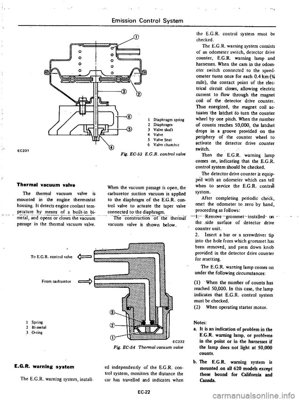
The
thermal
vacuum
valve
is
mounted
in
the
engine
thermostat
housing
It
detects
engine
coolan
t
tem
perature
by
means
of
a
built
in
bi
metal
and
opensor
closes
the
vacuum
passage
in
the
thermal
vacuum
valve
mt
li
t
00
t
EC232
Fig
EC
54
Thennal
vacuum
valve
To
E
G
R
control
valve
From
carburetor
1
Spring
2
Bi
metal
3
O
ring
E
G
R
warning
system
The
E
G
R
warning
system
install
1
Diaphragm
spring
2
Diaphragm
3
Valve
shaft
4
Valve
5
Valve
Seat
6
Valve
cham
ber
Fig
EC
53
E
G
R
control
value
When
the
vacuum
passage
is
open
the
carburetor
suction
vacuum
is
applied
to
the
diaphragm
of
the
E
G
R
con
trol
valve
to
actuate
the
taper
valve
connected
to
the
diaphragm
theconsiiiictlo
nlie
thermal
vacuum
valve
is
shown
below
ed
independently
of
the
E
G
R
con
trol
system
monitors
the
distance
the
car
has
travelled
and
indicates
when
EC
22
the
E
G
R
control
system
must
be
checked
The
E
G
R
warning
system
consists
of
an
odometer
switch
detector
drive
counter
E
G
R
warning
lamp
and
harnesses
When
the
earn
in
the
odom
eter
switch
connected
to
the
speed
ometer
turns
once
for
each
OAkm
4
mile
the
contact
point
of
the
elec
trica
circuit
closes
allowing
electric
current
to
flow
through
the
magnet
coil
of
the
detector
drive
counter
Thus
energized
the
magnet
coil
ac
Wates
the
latchet
to
turn
the
c
unter
wheel
by
one
pitch
When
the
number
of
counts
reaches
50
000
the
latchet
drops
in
a
groove
provided
on
the
periphery
of
the
counter
wheel
to
activate
the
detector
drive
counter
switch
Then
the
E
G
R
warning
lamp
comes
on
indicating
that
the
E
G
R
control
system
Should
be
checked
The
detector
drive
coun
teT
is
equip
ped
with
an
odometer
which
can
tell
when
to
service
the
E
G
R
contr0
I
system
After
completing
periodic
check
reset
the
odometer
to
zero
by
hand
proceeding
as
follows
1
Remove
grommet
installed
on
the
side
surface
of
detector
drive
counter
unit
2
insert
a
bar
or
a
screwdriver
tip
into
the
hole
from
which
grommet
has
been
removed
and
press
down
knob
provided
in
the
detector
drive
counter
for
resetting
The
E
G
R
warning
lamp
comes
on
under
the
following
circumstances
1
When
the
number
of
counts
has
reached
50
000
In
this
case
the
lamp
indicates
that
E
G
R
control
system
must
be
checked
2
When
operating
starter
motor
Notes
a
It
is
an
indication
of
problem
in
the
E
G
R
warning
lamp
or
problems
in
the
point
or
in
the
harnesses
if
the
lamp
does
not
light
at
50
000
counts
b
The
E
G
R
warning
system
is
mounted
on
all
620
models
except
those
bound
for
California
and
Canada
Page 157 of 537
4
E
G
R
warning
system
EC251
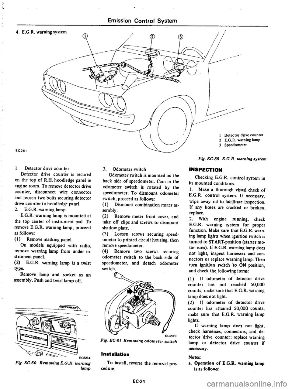
Detector
drive
counter
Detecfor
drive
counter
is
secured
on
the
top
of
R
H
hoodledge
panel
in
engine
room
To
remove
detector
drive
counter
disconnect
w
COJUlector
and
loosen
two
bolts
securing
detector
drive
counter
to
hoodledge
panel
2
E
G
R
warning
lamp
E
G
R
warning
lamp
is
mounted
at
the
top
cen
ter
of
instrument
pad
To
remove
E
G
R
warning
lamp
proceed
as
follows
1
Remove
masking
panel
On
models
equipped
with
radio
remove
warning
lamp
from
under
in
strument
panel
2
E
G
R
warning
lamp
is
a
twist
type
Remove
lamp
and
socket
as
an
assembly
Push
and
twist
lamp
off
can
EC554
Fig
EC
60
Removing
E
G
R
warning
lamp
Emission
Control
System
3
Odometer
switch
Odometer
switch
is
mounted
on
the
back
side
of
speedometer
Cam
in
the
odometer
switch
is
rotated
by
the
speedometer
To
dismount
odometer
switch
proceed
as
follows
I
Dismount
combination
meter
as
sembly
2
Remove
meter
front
cover
and
take
off
clips
and
screws
to
dismount
shadow
plate
3
Loosen
screws
securing
speed
ometer
to
printed
circuit
housing
then
remove
speedometer
4
Remove
two
screws
securing
odomete
switch
to
the
back
side
of
speedometer
and
detach
odometer
switch
EC239
Fig
EC
61
Removing
odometer
switch
InstaUatlon
To
install
reverse
the
removal
pro
cedure
EC24
V
r
CID
1
Detector
drive
counter
2
E
G
R
warning
lamp
3
Speedometer
Fig
EC
59
E
G
R
warning
y
tem
INSPECTION
Checking
E
G
R
control
system
in
its
mounted
conditionS
I
Make
a
thorough
visual
check
of
E
G
R
control
system
If
necessary
wipe
away
oil
to
facilitate
inspection
If
any
hoses
are
cracked
or
broken
replace
2
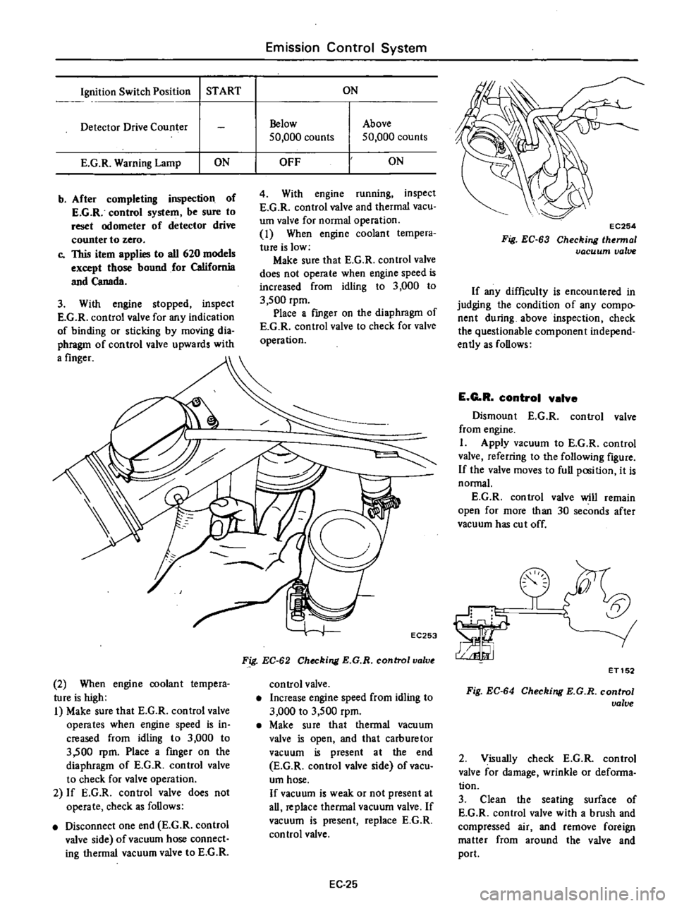
With
engine
running
check
E
G
R
warning
system
for
proper
function
Make
sure
that
E
G
R
warn
ing
lamp
lights
when
ignition
switch
is
turned
to
START
position
starter
mo
tor
runs
If
E
G
R
wanung
lamp
does
not
light
inspect
harnesses
and
con
nectors
or
replace
warning
lamp
Then
turn
ignition
switch
to
ON
position
and
check
the
following
items
I
If
odometer
of
detector
drive
counter
has
not
reached
50
000
counts
make
sure
that
E
G
R
warning
lamp
does
not
light
2
If
odomete
of
detector
drive
counter
has
attained
50
000
counts
make
sure
that
E
G
R
warning
lamp
lights
If
warning
lamp
does
not
light
check
harnesses
connectors
and
de
tector
drive
counter
replace
warning
lamp
or
detector
drive
counter
if
necessary
Notes
Operation
oC
E
G
R
warning
lamp
is
as
Collows
Page 158 of 537
Ignition
Switch
Position
START
Detector
Drive
Counter
E
G
R
Warning
Lamp
ON
b
After
completing
inspection
of
E
G
R
control
system
be
sure
to
reset
odometer
of
detector
drive
counter
to
zero
c
This
item
applies
to
all
620
models
except
those
bound
for
California
and
Canada
3
With
engine
stopped
inspect
E
G
R
control
valve
for
any
indication
of
binding
or
sticking
by
moving
dia
phragm
of
control
valve
upwards
with
a
finger
2
When
engine
coolant
tempera
ture
is
high
I
Make
sure
that
E
G
R
control
valve
operates
when
engine
speed
is
in
creased
from
idling
to
3
000
to
3
500
rpm
Place
a
fmger
on
the
diaphragm
of
E
G
R
control
valve
to
check
for
valve
operation
2
If
E
G
R
control
valve
does
not
operate
check
as
follows
Disconnect
one
end
E
G
R
control
valve
side
of
vacuum
hose
connect
ing
thermal
vacuum
valve
to
E
G
R
Emission
Control
System
ON
Below
50
000
counts
Above
50
000
counts
OFF
ON
4
With
engine
running
inspect
E
G
R
control
valve
and
thermal
vacuo
um
valve
for
normal
operation
1
When
engine
coolant
tempera
ture
is
low
Make
sure
that
E
G
R
control
valve
does
not
operate
when
engine
speed
is
increased
from
idling
to
3
000
to
3
500
rpm
Place
a
fmger
on
the
diaphragm
of
E
G
R
control
valve
to
check
for
valve
operation
EC253
Fig
EC
62
Checking
E
G
R
control
valve
control
valve
Increase
engine
speed
from
idling
to
3
000
to
3
500
rpm
Make
su
re
that
thermal
vacu
um
valve
is
open
and
that
carburetor
vacuum
is
present
at
the
end
E
G
R
control
valve
side
of
vacu
um
hose
If
vacuum
is
weak
or
not
present
at
all
replace
thermal
vacuum
valve
If
vacuum
is
present
replace
E
G
R
control
valve
EC
25
EC254
Fig
EC
63
Checking
lhermal
vacuum
valve
If
any
difficulty
is
encountered
in
judging
the
condition
of
any
compo
nent
during
above
inspection
check
the
questionable
component
independ
ently
as
follows
E
G
R
control
valve
Dismount
E
G
R
control
valve
from
engine
I
Apply
vacuum
to
E
G
R
control
valve
referring
to
the
following
figure
If
the
valve
moves
to
full
position
it
is
normal
E
G
R
control
valve
will
remain
open
for
more
than
30
seconds
after
vacuum
has
cut
off
la
ET152
Fig
EC
64
Checking
E
G
R
control
ualue
2
Visually
check
E
G
R
control
valve
for
damage
wrinkle
or
defonna
tion
3
Clean
the
seating
surface
of
E
G
R
control
valve
with
a
brush
and
compressed
air
and
remove
foreign
matter
from
around
the
valve
and
port