fuel DATSUN PICK-UP 1977 Manual PDF
[x] Cancel search | Manufacturer: DATSUN, Model Year: 1977, Model line: PICK-UP, Model: DATSUN PICK-UP 1977Pages: 537, PDF Size: 35.48 MB
Page 219 of 537
Engine
Removal
Installation
ENGINE
REMOVAL
AND
INSTAllATION
REMOVAL
INSTALLATION
ENGINE
MOUNTING
INSULATORS
REMOVAL
It
is
much
easier
to
remove
engine
and
transmission
as
a
single
unit
than
to
remove
them
separately
After
re
moval
engine
can
be
separated
from
transntission
assembly
Notes
a
Be
sure
to
hoist
engine
and
jack
up
transmission
in
a
safe
manner
b
Use
fender
cove
to
protect
vehicle
body
1
Remove
battery
2
Scribe
hood
hinge
location
for
proper
reinstallation
and
remove
hood
Note
Have
an
assistant
help
you
so
as
to
prevent
damage
to
body
3
Drain
radiator
coolant
4
Disconnect
upper
and
lower
radiator
hoses
from
engine
5
Remove
two
oil
cooler
hoses
from
lower
end
of
radiator
Auto
ma
tic
transmission
models
only
6
Remove
radiator
shroud
7
Remove
four
bolts
securing
radia
tor
and
detach
radiator
Note
Always
tighten
securing
bolt
at
upper
right
hand
side
together
with
body
harness
terminal
8
Remove
carburetor
air
cleaner
as
follows
Remove
fresh
air
duct
Remove
hot
air
duct
Loosen
air
cleaner
band
bolt
and
air
cleaner
supporting
bolts
Disconnect
air
cleaner
ta
air
pump
hose
Disconnect
air
cleaner
to
rocker
cover
hose
at
rocker
cover
Disconnect
air
cleaner
to
air
control
valve
hose
California
models
only
CONTENTS
ER
2
ER
3
ER
3
FRONT
INSULATOR
REAR
INSULATOR
TIGHTENING
TORQUE
ER
4
ER
4
ER
4
Disconnect
air
deaner
to
A
B
valve
hose
Disconnect
air
cleaner
ta
vacuum
hoses
Note
Protect
carburetor
from
dust
and
foreign
matter
by
placing
cover
over
air
inlet
opening
9
Disconnect
fuel
pump
to
fuel
fdter
hose
and
return
hose
10
Disconnect
carbon
canister
hose
on
engine
side
II
Disconnect
air
pump
air
C1eaner
to
al
p
p
hose
12
Disconnect
following
cables
wires
and
hoses
Engine
ground
cable
Accelerator
wire
at
carburetor
High
tension
cable
between
ignition
coil
and
distributor
Wire
to
distributor
at
body
ter
minal
Wire
to
oil
pressure
switch
Wires
to
thermal
transmitter
Wires
to
B
C
p
D
cut
solenoid
Non
California
models
only
auto
choke
heater
and
anti
dieseling
solenoid
Wires
to
alternator
Wires
to
starter
motor
Heater
inlet
and
outlet
hoses
if
so
equipped
Vacuum
hose
of
Master
Vac
at
in
taJce
manifold
Wires
for
back
up
lamp
switch
Cable
to
speedometer
13
Remove
transmission
control
linkage
from
transmission
Manual
transmission
models
I
Detach
rubber
boot
2
Remove
E
ring
and
control
lever
pin
from
transmission
striking
rod
guide
and
remove
control
lever
ER
2
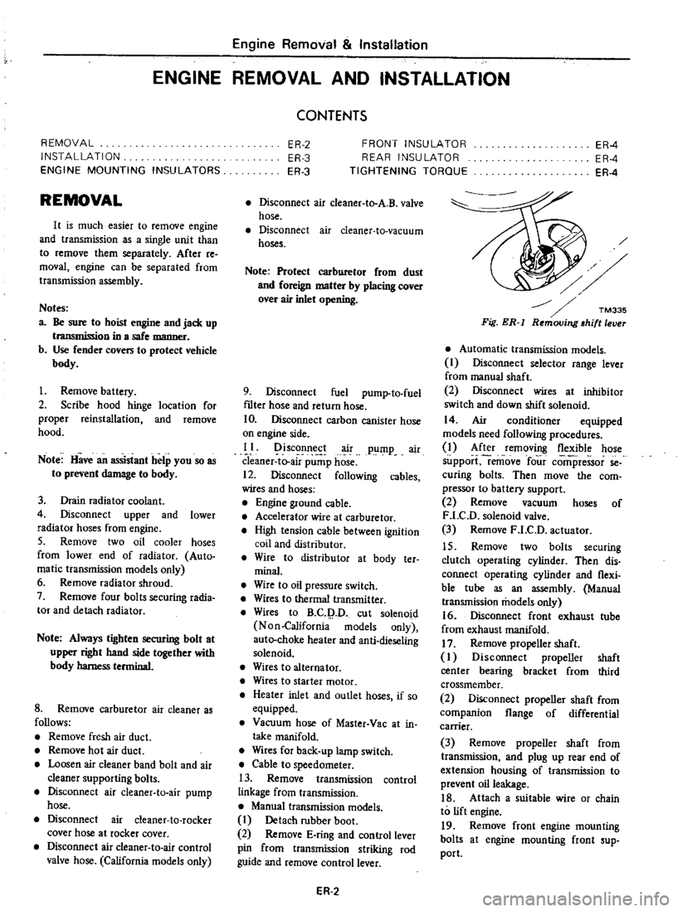
Fig
ER
l
Automatic
transmission
models
I
Disconnect
selector
range
lever
from
manual
shaft
2
Disconnect
wires
at
inhibitor
switch
and
down
shift
solenoid
14
Air
conditioner
equipped
models
need
following
procedures
1
After
removing
flexible
hose
support
remove
four
comi
ressor
se
curing
bolts
Then
move
the
com
pressor
to
battery
support
2
Remove
vacuum
hoses
of
F
LC
D
solenoid
valve
3
Remove
F
LC
D
actuator
15
Remove
two
bolts
securing
clutch
operating
cylinder
Then
dis
connect
operating
cylinder
and
flexi
ble
tube
as
an
assembly
Manual
transmission
models
only
16
Disconnect
front
exhaust
tube
from
exhaust
manifold
17
Remove
propeller
shaft
I
Disconnect
propeller
shaft
center
bearing
bracket
from
third
crossmember
2
Disconnect
propeller
shaft
from
companion
flange
of
differential
carrier
3
Remove
propeller
shaft
from
transmission
and
plug
up
rear
end
of
extension
housing
of
transmission
to
prevent
oil
leakage
18
Attach
a
suitable
wire
or
chain
to
lift
engine
19
Remove
front
engine
mounting
bolts
at
engine
mounting
front
sup
port
Page 257 of 537
Manual
Transmission
I
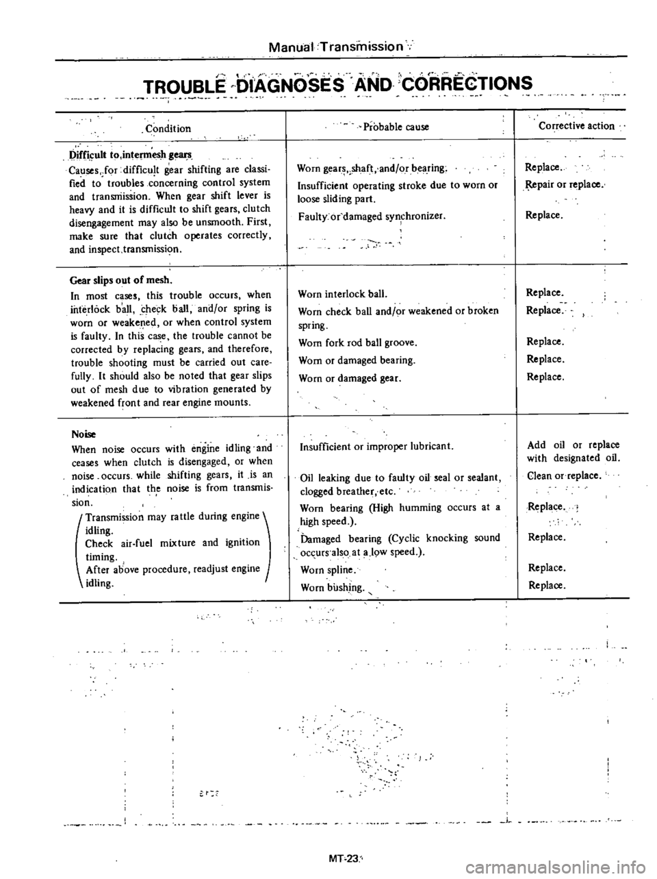
TROUBLE
DIAGNOSES
AND
CORREGTIONS
Condition
Difficult
to
intel11lesh
gears
Causes
Jor
difficu
t
gear
shifting
are
classi
fied
to
troubles
concerning
control
system
and
transniissioo
When
gear
shift
lever
is
heavy
and
it
is
difficult
to
shift
gears
clutch
disengagement
may
also
be
unsmooth
First
make
sure
that
clutch
operates
correctly
and
inspect
transmissi
o
Gear
slips
out
of
mesh
In
most
cases
this
trouble
occurs
when
interlock
b
all
check
ball
and
or
spring
is
worn
or
weakened
or
when
control
system
is
faulty
In
this
case
the
trouble
cannot
be
corrected
by
replacing
gears
and
therefore
trouble
shooting
must
be
carried
out
care
fully
It
should
also
be
noted
that
gear
slips
out
of
mesh
due
to
vibration
generated
by
weakened
fron
t
and
rear
engine
mounts
Noise
When
noise
occurs
with
engine
idling
and
ceases
when
clutch
is
disengaged
or
when
noise
occurs
while
shifting
gears
it
is
an
indicati90
that
th
e
noise
is
from
transmis
sion
t
Transmission
may
fa
ule
during
engine
idling
Check
air
fuel
mixture
and
ignition
timing
After
above
procedure
readjust
engine
idling
Probable
cause
Worn
gear
shaft
and
or
bearing
Insufficient
operating
stroke
due
to
worn
or
loose
sliding
part
Faulty
or
damaged
synchronizer
Worn
interlock
ball
Worn
check
ball
and
or
weakened
or
broken
spring
Wom
fork
rod
ball
groove
Wom
or
damaged
bearing
Worn
or
damaged
gear
Insufficient
or
improper
lubricant
Oil
leaking
due
to
faulty
oil
seal
or
sealant
clogged
breather
etc
Worn
bearing
High
humming
occurs
at
a
high
speed
Damaged
bearing
Cyclic
knocking
sound
occurs
also
at
a
19W
speed
Worn
spline
Worn
bushing
j
MT
23
Corrective
action
Replace
pair
or
replace
Replace
Replace
Replace
Replace
Replace
Replace
Add
oil
or
replace
with
designated
oil
Clean
Of
replace
Replace
Replace
Replace
Replace
Page 358 of 537
s
Install
tension
rod
at
rear
end
tighten
nut
to
make
the
distance
of
rubber
bushing
to
be
33
4
mm
1
315
in
and
torque
lock
nut
to
1
6
to
2
2
kg
m
12
to
16
ft
lb
6
Install
tension
rod
bracket
to
chassis
frame
bracket
and
torque
nut
to
1
6
to
2
2
kg
m
12
to
16
ft
lb
When
two
rubber
bushings
are
dif
ferent
in
size
arrange
adjusting
nut
Standard
dimension
is
11
0
mOl
0
433
in
as
shown
in
Figure
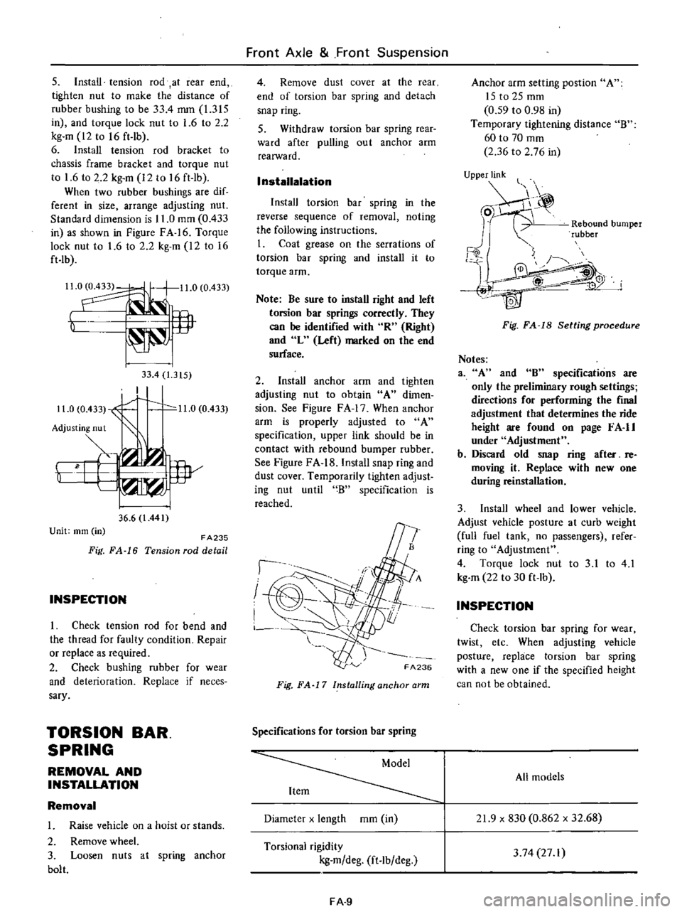
FA
16
Torque
lock
nut
to
1
6
to
2
2
kg
m
12
to
16
ft
lb
Il
0
11
0
0
433
t
lP
33
4
1
315
I
11
0
0
433
1
0
11
0
0
433
Adjusting
nut
Y
i
w
36
6
l
441
Unit
mm
in
FA235
Fig
FA
16
Tension
rod
detail
INSPECTION
I
Check
tension
rod
for
bend
and
the
thread
for
faulty
condition
Repair
or
replace
as
required
2
Check
bushing
rubber
for
wear
and
deterioration
Replace
if
neces
sary
TORSION
BAR
SPRING
REMOVAL
AND
INSTALLATION
Removal
1
Raise
vehicle
on
a
hoist
or
stands
2
Remove
wheel
3
Loosen
nuts
at
spring
anchor
bolt
Front
Axle
Front
Suspension
4
Remove
dust
cover
at
the
rear
end
of
torsion
bar
spring
and
detach
snap
ring
S
Withdraw
torsion
bar
spring
rear
ward
after
pulling
ou
t
anchor
arm
realWard
I
nstallalation
Install
torsion
bar
spring
in
the
reverse
sequence
of
removal
noting
the
following
instructions
I
Coat
grease
on
the
serrations
of
torsion
bar
spring
and
install
it
to
torque
arm
Note
Be
sure
to
install
right
and
left
torsion
bar
springs
correctly
They
can
be
identified
with
R
Right
and
L
Left
marked
on
the
end
surface
2
Install
anchor
arm
and
tighten
adjusting
nut
to
obtain
A
dimen
sion
See
Figure
F
A
17
When
anchor
arm
is
properly
adjusted
to
A
specification
upper
link
should
be
in
contact
with
rebound
bumper
rubber
See
Figure
FA
18
Install
snap
ring
and
dust
cover
Temporarily
tighten
adjust
ing
nut
until
B
specification
is
reached
I
I
I
FA236
Fig
FA
17
Installing
anchor
arm
Specifications
for
torsion
bar
spring
Diameter
x
length
mOl
in
Torsional
rigidity
kg
m
deg
ft
lb
deg
FA
9
Anchor
arm
setting
post
ion
A
ISt02Smm
0
59
to
0
98
in
Temporary
tightening
distance
B
60
to
70
mOl
2
36
to
2
76
in
UjPPje
Rebound
bumper
rubber
j
4W
Fig
FA
18
Setting
procedure
Notes
3
A
and
8
specifications
are
only
the
preliminary
rough
settings
directions
for
performing
the
final
adjustment
that
determines
the
ride
height
are
found
on
page
F
A
II
under
Adjustment
b
Discard
old
snap
ring
after
re
moving
it
Replace
with
new
one
during
reinstallation
3
Install
wheel
and
lower
vehicle
Adjust
vehicle
posture
at
curb
weight
full
fuel
tank
no
passengers
refer
ring
to
Adjustment
4
Torque
lock
nut
to
3
1
to
4
1
kg
m
22
to
30
ft
lb
INSPECTION
Check
torsion
bar
spring
for
wear
twist
etc
When
adjusting
vehicle
posture
replace
torsion
bar
spring
with
a
new
one
if
the
specified
height
can
not
be
obtained
All
models
21
9
x
830
0
862
x
32
68
3
74
27
I
Page 416 of 537

DATSUN
PICK
UP
MODEL
620
SERIES
l
NISSAN
I
NISSAN
MOTOR
CO
LTD
TOKYO
JAPAN
SECTION
FE
ENGINE
CONTROL
FUEL
EXHAUST
SYSTEMS
ENGINE
CONTROL
SYSTEM
FUEL
SYSTEM
EXHAUST
SYSTEM
FE
2
FE
4
FE
6
Page 417 of 537
Engine
Control
Fuel
Exhaust
Systems
ENGINE
CONTROL
SYSTEM
CONTENTS
DESCRIPTION
REMOVAL
AND
INSTAllATION
INSPECTION
ADJUSTMENT
FE
2
FE
3
DESCRIPTION
The
accelerator
control
system
is
of
flexible
cable
type
so
that
the
linkage
operates
smoothly
and
the
system
is
not
affected
by
engine
vibration
u
l
f
L
4
@
Arrow
B
E
78
mm
3
07
in
T
2
to
4
mm
0
08
to
0
16
in
MUlti
purpose
grease
FE
3
FE
3
The
choke
system
is
automatically
controlled
i
p
@
I
@
@
CV
j
I
Accelerator
pedal
II
Screw
2
Accelerator
pedal
bracket
12
Pedal
stopper
bolt
and
return
spring
13
Kickdown
switch
striker
3
Accelerator
pedal
arm
Automatic
transmission
4
Pedal
stopper
lock
nut
models
only
5
S
pring
clamp
14
Kickdown
switch
6
Lock
nut
Automatic
transmission
7
Adjust
nut
models
only
8
Wire
holder
15
Switch
stopper
nu
t
9
Accelerator
wire
16
Carburetor
10
Accelerator
wire
outer
case
FE
2
FE260
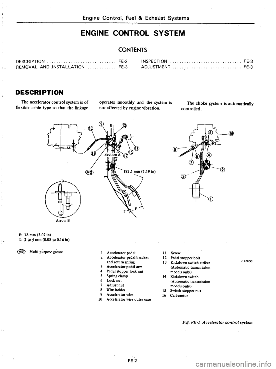
Fig
FE
l
Accelerator
control
sy
t
m
Page 418 of 537
Engine
Control
Fuel
Exhaust
Systems
REMOVAL
AND
INSTALLATION
Accelerator
wire
I
Remove
air
cleaner
assembly
2
Disconnect
accelerator
wire
from
carburetor
3
Loosen
lock
nut
and
disconnect
accelerator
wire
outer
case
from
wire
holder
See
Figure
FE
I
4
Remove
spring
clamp
and
discon
nect
accelerator
wire
from
accelerator
pedal
arm
S
Remove
two
screws
securing
ac
celerator
wire
outer
case
to
body
and
detach
accelerator
wire
6
To
install
reverse
the
order
of
removal
Apply
recommended
multi
purpose
grease
slightly
to
portion
MG
shown
in
Figure
FE
I
Accelerator
pedal
assembly
I
Remove
spring
clamp
then
dis
connect
accelerator
wire
from
tip
of
pedal
ann
2
Remove
two
screws
securing
ac
celerator
pedal
bracket
to
body
3
Remove
accelerator
pedal
from
dash
panel
See
Figure
FE
I
4
To
install
reverse
the
order
of
removal
INSPECTION
I
Check
accelerator
pedal
return
spring
for
rust
fatigue
or
damage
Replace
if
necessary
2
Check
accelerator
wire
cases
and
fastening
locations
for
rust
damage
or
looseness
Repair
or
replace
if
necessary
ADJUSTMENT
Accelerstor
pedal
and
wire
Adjust
pedal
stopper
bolt
Section
A
so
as
to
obtain
specifi
ed
height
E
as
shown
in
Figure
FE
I
Secure
pedal
stopper
bolt
with
stopper
lock
nut
Refer
to
Figure
FE
I
E
78
mOl
3
07
in
Tightening
torque
01
nut
0
38
to
0
4S
kg
m
2
7
to
3
2
ft
b
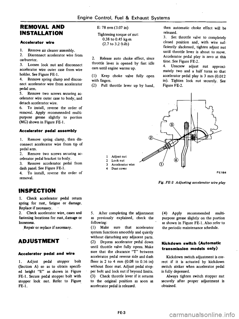
2
Release
auto
choke
effect
since
throttle
lever
is
opened
by
fast
idle
earn
until
engine
warms
up
I
Keep
choke
valve
fully
open
with
fingers
2
Pull
throttle
lever
up
by
hand
1
Adjust
nut
2
Lock
nut
3
Accelerator
wire
4
Dust
co
r
5
After
completing
the
adjustment
as
previously
explained
check
the
following
I
Make
sure
that
accelerator
system
functions
smoothly
and
quietly
without
disturbing
any
adjacent
parts
2
Depress
accelerator
pedal
down
until
throttle
valve
fully
opens
Make
sure
that
the
clearance
T
between
accelerator
pedal
reverse
side
and
dash
floor
is
2
to
4
mm
0
08
to
0
16
in
without
floor
mat
Adjust
pedal
stop
per
bolt
and
lock
nut
if
beyond
limits
3
Check
throttle
lever
if
it
returns
to
the
original
position
as
soon
as
accelerator
pedal
is
released
FE
3
then
automatic
choke
effect
will
be
released
3
Set
throttle
valve
to
completely
closed
position
and
with
wire
suf
ficiently
slackened
lighten
adjust
nut
until
throttle
lever
is
about
to
move
Accelerator
pedal
play
is
zero
at
this
lime
See
Figure
FE
2
4
Unscrew
adjust
nut
approxi
mately
two
and
a
half
turns
so
that
accelerator
pedal
play
is
3
mOl
0
012
in
Tighten
lock
nut
securely
See
Figure
FE
2
1
I
1
CD
@
FE184
Fig
FE72
AdjU6ting
accelerator
wire
play
4
Apply
recommended
multi
purpose
grease
slightly
on
the
portion
as
shown
in
Figure
FE
I
Also
refer
to
the
periodic
maintenance
schedule
Kickdown
switch
Automatic
transmission
models
only
Kickdown
switch
adjustment
is
cor
rect
if
it
is
actuated
by
kickdown
switch
striker
when
accelerator
pedal
is
fully
depressed
Always
tighten
switch
stopper
nut
securely
after
proper
adjustment
is
obtained
Page 419 of 537

DESCRIPTION
REMOVAL
DESCRIPTION
The
fuel
tank
is4Sliters
II
Ji
U
s
gal
9
Ji
Imper
gal
in
capacity
The
tank
unit
is
mounted
to
the
right
side
of
the
rear
floor
1
Fuel
tank
2
Drain
plug
3
Filler
tube
4
RescfYOir
tank
5
Filler
hose
6
Breather
hose
7
Ventilation
hose
8
Evaporation
hose
9
Fuel
outlet
hose
and
tube
10
Fuel
tank
gauge
unit
11
Protector
12
Bracket
13
Retainer
14
Return
tube
Engine
Control
Fuel
Exhaust
Systems
FUEL
SYSTEM
CONTENTS
FE
4
FE
5
INSPECTION
INSTALLATION
FE
6
FE
6
The
filler
shutter
is
installed
to
the
filler
tube
on
California
models
The
electric
fuel
pump
is
adopted
on
air
conditioner
equipped
models
For
the
electric
fuel
pump
refer
to
Section
EF
FE194
Fig
FE
3
Fuel
tank
FE
4
Page 420 of 537
Detail
A
Detail
D
REMOVAL
Engine
Control
Fuel
Exhaust
Systems
Detail
Bn
4
Detail
e
@
Detail
E
B
Fuel
tank
See
Figure
FE
a
I
Disconnect
battery
ground
cable
2
Remove
drain
plug
and
receive
the
remaining
fuel
into
a
suitable
container
3
Disconnect
filler
tube
fro
filler
hose
4
Remove
fuel
tank
securing
bolts
5
Disconnect
two
ventilation
hoses
fuel
return
hose
and
fuel
outlet
hose
from
fuel
tank
6
Disconnect
fuel
tank
gauge
unit
wires
at
connector
7
Remove
fuel
tank
Note
Plug
hose
and
tube
opening
l
to
prevent
entry
of
dust
or
dirt
while
removing
ReservoIr
tank
1
Disconnect
battery
ground
cable
2
Disconnect
two
ventilation
hoses
evaporation
hose
and
breather
hose
3
Remove
reservoir
tank
securing
bolts
and
remove
tank
with
protector
Note
Plug
hose
and
tube
opening
l
to
prevent
entry
of
dust
or
dirt
while
removing
Fuel
tank
gauge
unit
Disconnect
battery
ground
cable
2
Disconnect
wires
from
fuel
tank
gauge
unit
3
Remove
fuel
tank
For
details
refer
to
fuel
tank
removal
4
Unit
gauge
is
a
bayonet
type
and
can
be
removed
by
turning
it
counter
clockwise
with
screwdriver
Fuel
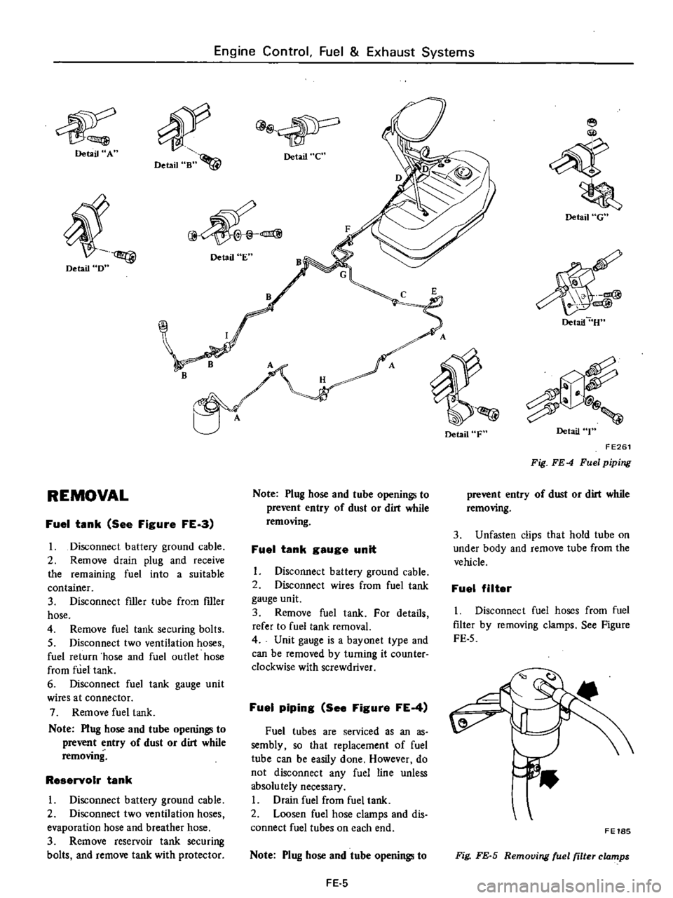
piping
See
Figure
FE
4
Fuel
tubes
are
serviced
as
an
as
sembly
so
that
replacement
of
fuel
tube
can
be
easily
done
However
do
not
disconnect
any
fuel
line
unless
absolu
tely
necessary
I
Drain
fuel
from
fuel
tank
2
Loosen
fuel
hose
clamps
and
dis
connect
fuel
tubes
on
each
end
Note
Plug
hose
and
tube
openings
to
FE
5
Detail
F
Detail
G
Detail
U
Detail
T
FE261
Fig
FE
4
Fuel
piping
prevent
entry
of
dust
or
dirt
while
removing
3
Unfasten
clips
that
hold
tube
on
under
body
and
remove
tube
from
the
vehicle
Fuel
filter
I
Disconnect
fuel
hoses
from
fuel
filter
by
removing
clamps
See
Figure
FE
5
FE18S
Fig
FE
S
Removing
fuel
filter
clamps
Page 421 of 537
Engine
Control
Fuel
Exhaust
Systems
2
Remove
fuel
filter
INSPECTION
Fuel
tanle
Check
fuel
tank
for
cracks
or
deformation
If
necessary
replace
2
Fuel
hose
Inspect
all
hoses
for
cracks
fatigue
sweating
or
deterioration
Replace
any
hose
that
is
damaged
3
Fuel
tube
Replace
any
fuel
tube
that
is
crack
ed
rusted
collapsed
or
deformed
Note
Inspect
hoses
and
tubes
ac
cording
to
the
periodic
mainte
nance
schedule
4
Fuel
filter
Replace
fuel
filter
according
to
the
periodic
maintenance
schedule
or
when
it
is
clogged
or
restricted
DESCRIPTION
REMOVAL
DESCRIPTION
The
exhaust
systems
installed
on
the
non
California
models
differ
in
specifications
from
those
installed
on
the
California
models
Fuel
filter
is
of
a
cartridge
type
and
cannot
be
cleaned
Always
replace
with
a
new
one
5
Fuel
tank
gauge
unit
Check
gauge
unit
for
rust
deforma
tion
or
deterioration
If
necessary
replace
INSTALLATION
To
install
reverse
the
order
of
removal
Observe
the
following
I
Install
hose
clamps
securely
Do
not
tighten
excessively
to
avoid
damaging
hoses
2
Fasten
clips
holding
fuel
tube
on
under
body
securely
Failure
to
follow
this
caution
could
result
in
damage
to
the
surface
of
fuel
tube
3
Do
not
kink
or
twist
hose
and
tube
when
they
are
routed
EXHAUST
SYSTEM
CONTENTS
FE
6
FE
8
INSPECTION
INSTAllATION
Non
California
models
The
exhaust
system
consists
of
a
front
exhaust
tube
a
main
muffler
assembly
with
rear
tube
mounting
hangers
brackets
and
a
heat
insulator
FE
6
4
Install
fIller
hose
after
fuel
tank
has
been
mounted
in
place
Failure
to
follow
this
caution
could
result
in
leakage
from
around
hose
connections
5
When
installing
fuel
tank
gauge
unit
align
the
projection
of
tank
gauge
unit
with
the
notch
in
fuel
tank
and
tighten
it
securely
Be
sure
to
install
gauge
unit
with
O
ring
in
place
6
Run
engine
and
check
for
leaks
at
connections
Tightening
torque
Drain
plug
5
0
to
6
0
kg
m
36
to
43
ft
Ib
Fuel
tank
securing
bolt
0
8
to
1
I
kg
m
6
to
8
ft
Ib
Reservoir
tank
securing
bolt
032
to
0
44
kg
m
2
to
3
ft
Ib
FE
8
FE
8
California
models
The
exhaust
system
cOllsists
of
a
front
exhaust
tube
a
catalytic
conver
ter
assembly
a
center
tube
a
main
muffler
assembly
with
rear
tube
mounting
hangers
brackets
and
heat
insulators
The
catalytic
converter
is
COD
nected
to
the
front
tube
and
the
center
tube
with
bolts
and
nuts
Page 422 of 537

Engine
Control
Fuel
Exhaust
S
t
ys
ems
Non
Califomia
model
Qf
@
Si
tr
l
Qf
Si
tIJ
i
Qf
I
l
j
l
tr
l
r
Qf
Si
i
l
l
t
1
I
tr
l
9
r
8
1Bi
1
Front
tube
2
Exhaust
tube
clamp
3
Rear
tube
assembly
4
Muffler
assembly
5
Rear
tube
mounting
6
Front
tube
mounting
California
model
6
@@
8
Qf
@
fit
J
0
I
1
2
I
7
Front
tube
Catalytic
converter
Center
tube
Muffler
assembly
Diffuser
Rear
tube
mounting
Front
tube
mounting
FE390
Fig
FE
6
E
r
ha
t
system
FE
7