clutch DATSUN PICK-UP 1977 Manual Online
[x] Cancel search | Manufacturer: DATSUN, Model Year: 1977, Model line: PICK-UP, Model: DATSUN PICK-UP 1977Pages: 537, PDF Size: 35.48 MB
Page 327 of 537
Automatic
Transmission
Tool
number
For
Reference
No
Description
use
page
or
tool
name
on
Figure
No
6
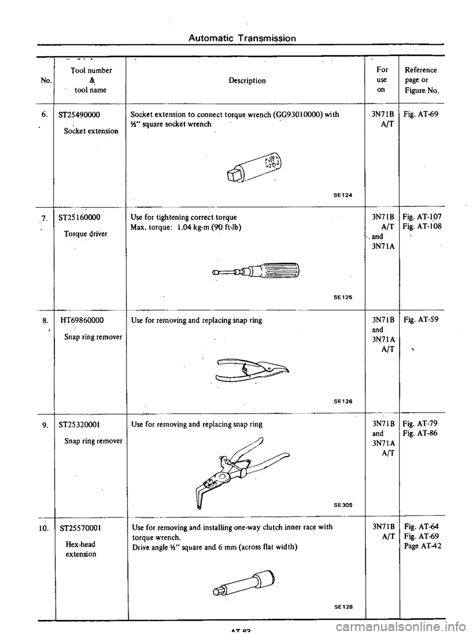
ST2S490000
Socket
extension
to
connect
torque
wrench
GG93010000
with
3N71B
Fig
AT
69
Socket
extension
W
square
socket
wrench
AIT
V
SE124
7
ST2S160000
Use
for
tightening
correct
torque
3N71B
Fig
AT
107
Torque
driver
Max
torque
1
04
kg
m
90
ft
lb
A
T
Fig
AT
108
and
3N71A
3
SE125
8
HT69860000
Use
for
removing
and
replacing
snap
ring
3N71B
Fig
AT
S9
and
Snap
ring
remover
3N71A
AIT
SE126
9
ST2S320001
Use
for
removing
and
replacing
snap
ring
3N71B
Fig
AT
79
and
Fig
AT
86
Snap
ring
remover
3N71A
AIT
SE305
Hex
head
extension
Use
for
removing
and
installing
one
way
clutch
inner
race
with
torque
wrench
Drive
angle
W
square
and
6
mOl
across
flat
width
3N71B
AIT
Fig
AT
64
Fig
AT
69
Page
AT
42
10
ST2SS70001
SE128
AT
I
Page 343 of 537
Condition
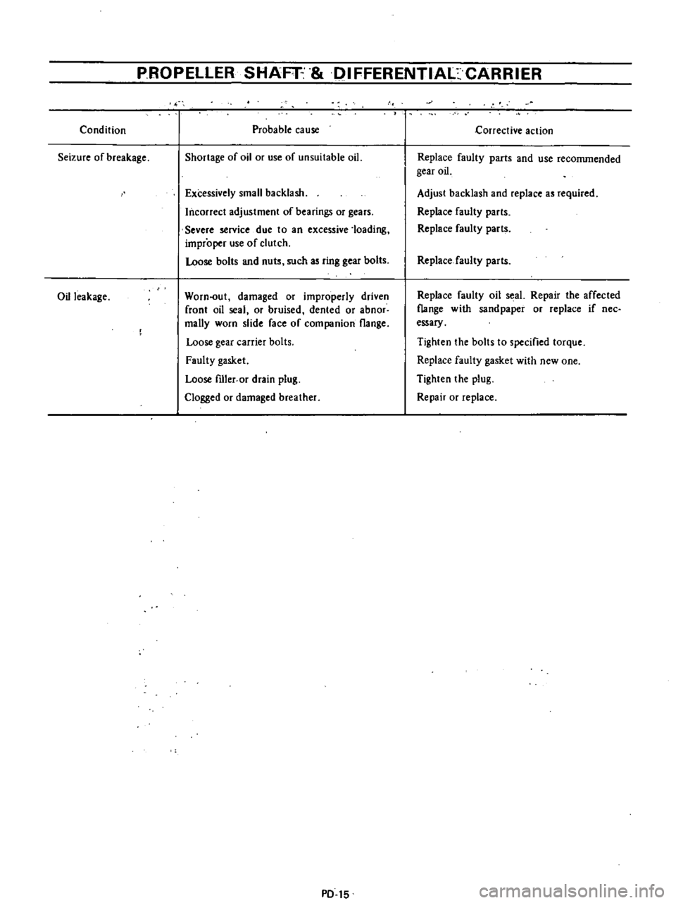
Seizure
of
breakage
Oil
leakage
PROPELLER
SHAFT
IFFERENTIAl
CARRIER
Probable
cause
Shortage
of
oil
or
use
of
unsuitable
oil
Excessively
small
backlash
Incorrect
adjustment
of
bearings
or
gears
Severe
service
due
to
an
excessive
loading
improper
use
of
clutch
Loose
bolts
and
nuts
such
as
ring
gear
bolts
Worn
out
damaged
or
improperly
driven
front
oil
seal
or
bruised
dented
or
abnor
mally
worn
slide
face
of
companion
flange
Loose
gear
carrier
bolts
Faulty
gasket
Loose
fIller
or
drain
plug
Clogged
or
damaged
breather
PD
15
1
j
Corrective
action
Replace
faulty
parts
and
use
reconunended
gear
oil
Adjust
backlash
and
replace
as
required
Replace
faulty
parts
Replace
faulty
parts
Replace
faulty
parts
Replace
faulty
oil
seal
Repair
the
affected
flange
with
sandpaper
or
replace
if
nee
essary
Tighten
the
bolts
to
specified
torque
Replace
faulty
gasket
with
new
one
Tighten
the
plug
Repair
or
replace
Page 428 of 537
CAB
BODY
Body
Frame
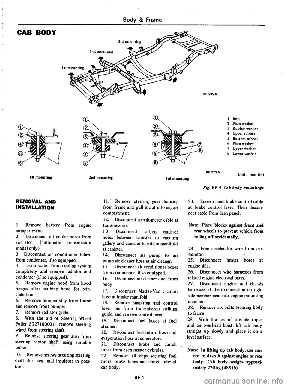
Ist
mounting
2nd
mounting
1
Bolt
2
Plain
washer
3
Rubber
washer
4
Upper
rubber
5
Bottom
rubber
6
Plain
w
er
7
Upper
washer
8
Lower
washer
1st
mounting
REMOVAL
AND
INSTALLATION
Remove
battery
from
engine
compartment
2
Disconnect
oil
cooler
hoses
from
radiator
automatic
transmission
model
only
3
Disconnect
air
conditioner
tubes
from
condenser
if
so
equipped
4
Drain
water
from
cooling
system
completely
and
remove
radiator
and
condenser
if
so
equipped
5
Remove
engine
hood
from
hood
hinges
after
scribing
hood
for
rein
stallation
6
Remove
bumper
stay
from
frame
and
remove
front
bumper
7
Remove
radiator
grille
8
With
the
aid
of
Steering
Wheel
Puller
ST27
180001
remove
steering
wheel
from
steering
shaft
9
Remove
steering
gear
arm
from
steering
sector
shaft
using
suitable
puller
10
Remove
screws
securing
steering
shaft
dust
seat
and
insulator
in
posi
tion
2nd
mounting
3rd
mounting
II
Remove
steering
gear
housing
from
frame
and
pull
it
out
into
engine
compartment
12
Disconnect
speedometer
cable
at
transmission
1
3
Disconnect
carbon
canister
hoses
between
canister
to
vacuum
gallery
and
canister
to
intake
manifold
at
canister
14
Disconnect
air
pump
to
air
pump
air
cleaner
hose
at
air
cleaner
15
Disconnect
air
conditioner
hoses
from
compressor
if
so
equipped
16
Disconnect
air
cleaner
duct
from
body
17
Disconnect
Master
Vac
vacuum
hose
at
intake
manifold
18
Remove
snap
ring
and
control
lever
pin
from
transmission
striking
guide
and
remove
control
lever
19
Disconnect
fuel
hoses
at
fuel
strainer
20
Disconnect
fuel
return
hose
and
evaporation
hose
at
connectors
21
Disconnect
brake
and
clutch
tubes
from
each
master
cylinder
22
Remove
all
clips
securing
fuel
tubes
brake
tubes
and
clutch
tube
at
cab
body
BF
4
BF472A
Unit
mm
in
Fig
BF
4
Cab
body
mountings
23
Loosen
hand
brake
control
cable
at
brake
control
lever
Then
discon
nect
cable
from
dash
panel
Note
Place
blocks
against
front
and
rear
wheels
to
prevent
vehicle
from
rolling
off
accidentally
24
Free
accelerator
wire
from
car
buretor
25
Disconnect
heater
hoses
at
engine
side
26
Disconnect
wire
harnesses
from
related
engine
electrical
parts
27
Disconnect
engine
and
chassis
harnesses
at
their
connection
on
right
sidemember
near
rear
engine
mounting
member
28
Remove
six
bolts
securing
body
to
frame
29
With
the
use
of
suitable
ropes
and
an
overhead
hoist
lift
cab
body
straight
up
slowly
and
place
it
on
a
level
surface
Note
In
lifting
up
cab
body
use
care
not
to
dash
it
against
engine
or
rear
body
Cab
body
weighs
approxi
mately
220
kg
485
Ib
Page 429 of 537
Body
Frame
30
For
installation
reverse
above
steps
However
observe
the
following
instructions
i
If
the
cab
body
is
to
be
replaced
note
position
and
location
of
insula
tors
and
washers
used
See
Figure
BF
4
2
Adjust
hand
brake
stroke
pro
perly
3
Air
bleed
brake
and
clutch
system
thorougWy
Cab
body
to
frame
mounting
bolt
torque
1
6
to
2
2
kg
m
12
to
16
ft
Ib
o
i
k
q
1Q
j
b
crru
V
J
8F630
rr
1
4
n
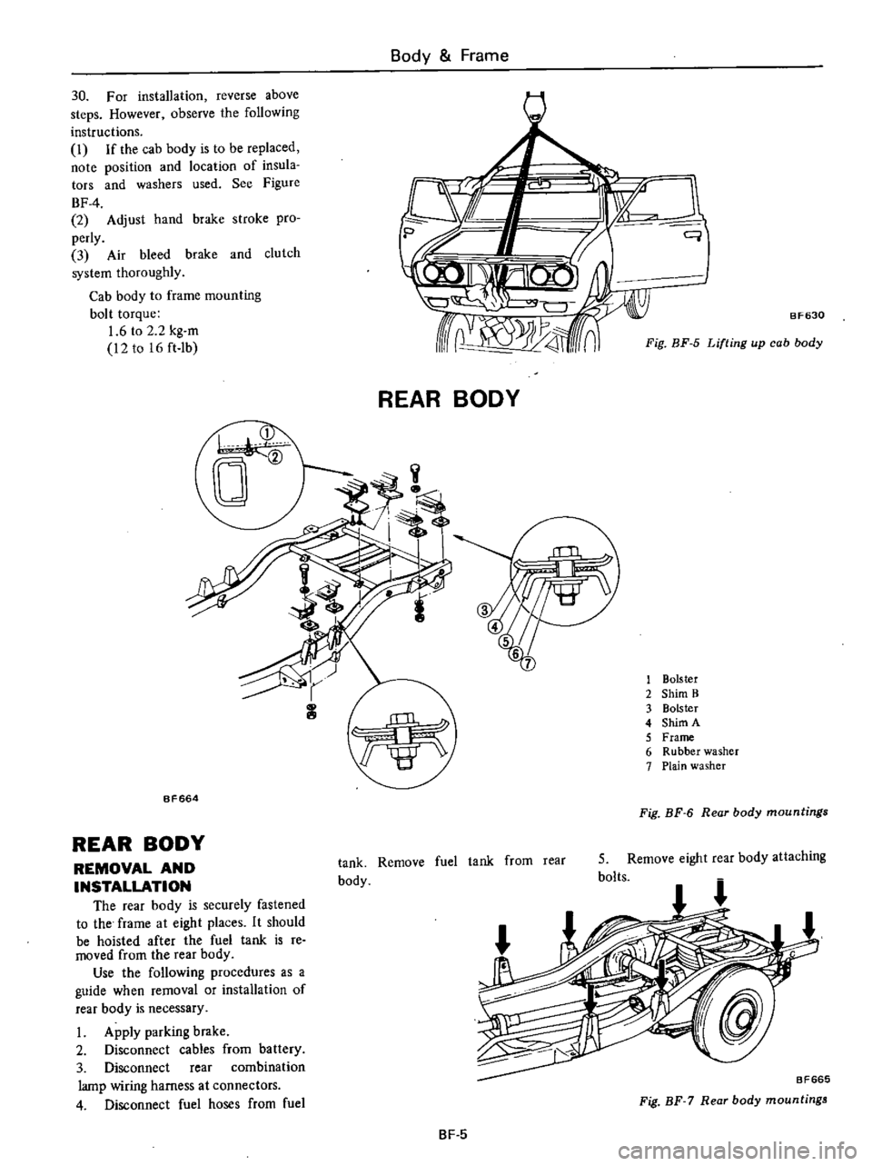
Fig
BF
5
Lifting
up
cab
body
REAR
BODY
1
Bolster
2
Shim
B
3
Bolster
4
Shim
A
5
Frame
6
Rubber
washer
7
Plain
washer
BF664
Fig
BF
6
Rear
body
mountings
REAR
BODY
REMOVAL
AND
INSTALLATION
The
rear
body
is
securely
fastened
to
the
frame
at
eight
places
It
should
be
hoisted
after
the
fuel
tank
is
re
moved
from
the
rear
body
Use
the
following
procedures
as
a
guide
when
removal
or
installation
of
rear
body
is
necessary
I
Apply
parking
brake
2
Disconnect
cables
from
battery
3
Disconnect
rear
combination
lamp
wiring
harness
at
connectors
4
Disconnect
fuel
hoses
from
fuel
tank
Remove
fuel
tank
from
rear
body
5
Remove
eight
rear
body
attaching
bolts
BF665
Fig
BF
7
Rear
body
mountings
BF
5
Page 492 of 537

REFRIGERATION
SYSTEM
If
you
were
to
paint
your
finger
with
alcohol
your
finger
would
feel
cold
This
is
because
the
liquid
alcohol
takes
heat
away
from
your
finger
while
it
evaporates
If
a
quickly
evapo
rating
liquid
such
as
alcoliol
is
placed
in
a
container
inside
a
box
the
tem
f
Outside
air
U
Condenser
J6G1
i
i
1
1
t1
1
ilill
I
I
J
JJ
LlJ
i
l
7
U
Receiver
dryer
h
w
t
CONDENSER
The
condenser
is
installed
to
the
front
of
the
radiator
The
heated
and
compressed
refrigerant
gas
from
the
Air
Conditioning
perature
inside
the
box
will
drop
This
is
because
the
alcohol
is
evaporated
absorbing
the
heat
from
the
air
insidc
the
box
If
the
gaseous
alcohol
is
collected
and
cooled
with
cold
water
it
will
be
changed
back
into
a
liquid
by
absorption
of
its
heat
by
the
cold
water
The
cooler
operates
on
this
princi
Compressor
t
q
ttLJ
IrJ
Evaporator
It
J
1
J
f
9
d
lUr
I
Expansion
valve
V7777
J
High
pressure
lLLLLL
l
gas
I
I
High
pressure
liquid
t
u
compressor
condenses
to
a
liquid
by
being
cooled
by
air
passing
between
the
fins
of
the
condenser
1
GJ
7
vlmnn
iii
plI
d1i
1il
Ac459
Fig
AC
3
Condenser
AC3
pIe
The
liquid
used
is
the
refrigerant
R
12
The
heat
inside
the
passenger
compartment
is
absorbed
by
changing
the
refrigerant
from
a
liquid
to
a
gas
and
then
dissipated
to
the
outside
by
changing
the
refrigerant
from
a
gas
back
to
a
liquid
The
refrigeration
system
is
shown
in
Figure
AC
2
Low
pressurt
liquid
1
I
L2
Low
pressure
gas
Inside
air
li
r
L
Blower
motor
AC458
Fig
AC
2
Refrigeration
cycle
COMPRESSOR
The
compressor
is
installed
to
the
side
of
the
engine
and
is
driven
by
crank
pulley
through
a
belt
The
refrig
erant
gas
leaving
the
evaporator
is
forced
out
to
the
condenser
by
com
pressor
and
the
low
pressure
refrig
erant
gas
is
compressed
to
a
high
pressure
and
high
temperature
The
driving
force
is
transmitted
by
an
electrical
clutch
Because
engine
rpm
is
very
low
during
idling
the
clutch
will
not
transmit
the
driving
force
thus
ensuring
smooth
engine
idling
Page 494 of 537

The
refrigerant
within
the
thermo
bulb
changes
in
pressure
through
the
super
heat
condition
of
vaporized
re
frigerant
gas
which
comes
out
of
the
evaporator
causing
the
deflection
of
the
diaphragm
The
lift
of
the
ball
valve
attached
to
the
diaphragm
is
changed
by
the
deflection
of
the
dia
phragm
thus
controlling
the
amount
of
refrigerant
passing
the
orifice
ELECTRICAL
CIRCUIT
DESCRIPTION
The
electrical
circuit
of
the
air
conditioner
consists
of
four
switches
two
relays
a
solenoid
valve
a
fan
motor
and
a
compressor
magnetic
clutch
Air
Conditioning
Diaphragm
Orifice
Valve
ball
AC729
4
Sensing
bulb
Fig
A
C
6
Expansion
value
The
following
wiring
diagram
pro
vides
a
complete
description
of
the
whole
circuit
When
the
ignition
switch
and
the
fan
switch
are
ON
the
main
relay
is
activated
causing
battery
power
to
flow
through
the
fan
motor
and
the
magnetic
clutch
The
magnetic
clutch
is
activated
by
the
thermo
switch
AC
5
000
l
1
Motor
2
Fan
3
Lower
case
4
Cooler
duct
5
Evaporator
6
Expansion
valve
7
Upper
case
8
Resistor
9
Main
relay
10
Thermo
switch
II
Cable
clamp
12
Cable
13
Harness
AC725
Fig
AC
7
Cooling
unit
pressure
switch
and
compressor
relay
The
blower
motor
fan
speed
is
con
trolled
by
the
fan
switch
and
resistor
The
solenoid
valve
is
also
activated
This
in
turn
causes
the
fast
idle
control
device
F
l
C
D
to
increase
engine
speed
when
the
vehicle
is
at
rest
with
the
engine
ON
Page 496 of 537

MAIN
RELAY
The
main
relay
is
located
on
the
cooling
unit
When
the
ignition
switch
and
fan
switch
are
both
turned
on
the
COll
@
FAN
SWITCH
The
fan
switch
serving
as
a
control
unit
is
installed
on
the
center
console
This
switch
controls
the
blower
motor
speed
through
the
resistor
It
is
also
used
as
a
main
relay
switch
Fig
AC
I0
Fan
switch
THERMO
SWITCH
The
thermo
switch
is
located
on
the
upper
side
of
the
cooling
unit
and
is
controlled
by
the
cable
and
the
con
trollever
attached
to
the
console
box
It
is
so
designed
that
when
the
air
passing
through
the
evaporator
core
is
cooled
down
to
the
predetermined
Air
Conditioning
tacts
in
the
relay
are
closed
Then
electrical
power
from
the
battery
is
supplied
to
the
blower
motor
and
the
electrical
clutch
for
the
compressor
@
Dc
IDe
ID
1
1
l@
@
e
L
J
AC465
Fig
A
C
9
Main
relay
temperature
set
by
the
control
lever
it
automatically
turns
off
When
the
switch
is
turned
off
the
magnetic
clutch
is
turned
off
stopping
the
flow
of
refrigerant
inside
the
cooling
system
and
increasing
the
cooling
system
tem
perature
When
the
air
rises
to
the
pre
determined
temperature
the
thermo
switch
automatically
turns
on
In
this
way
the
temperature
of
the
air
dis
charged
from
the
cooling
unit
is
auto
matically
controlled
as
desired
PRESSURE
SWITCH
The
pressure
switch
is
turned
off
when
refrigerant
pressure
in
the
cooling
system
rises
to
an
abnormally
high
level
28
kg
cm2
398
psi
This
in
turn
turns
off
the
compressor
magnetic
clutch
actuating
the
com
pressor
relay
and
gradually
decreasing
pressure
in
the
cooling
system
When
the
pressure
drops
to
or
below
24
kg
cm2
341
psi
the
pressure
switch
again
turns
on
Thus
cooling
system
refrigerant
pressure
is
automatically
maintained
at
the
proper
value
a
t
all
times
AC
7
COMPRESSOR
RERAY
The
compressor
relay
is
attached
to
the
receiver
dryer
bracket
on
the
right
side
of
the
engine
compartment
This
relay
is
actuated
by
the
fan
switch
thermo
switch
and
pressure
switch
to
turn
on
and
off
the
compressor
magnetic
clutch
cv
1
2
AC731
Fig
A
C
11
Pressure
switch
and
compressor
relay
F
I
C
D
SOLENOID
VALVE
The
F
l
C
D
solenoid
valve
is
at
tached
to
the
dash
panel
in
the
engine
compartment
This
valve
supplies
vacu
um
to
the
F
I
C
D
diaphragm
through
the
vacuum
hose
connected
to
the
engine
intake
manifold
when
the
engine
is
at
idle
and
the
cooling
system
is
ON
thereby
raising
idle
speed
to
the
predetermined
rpm
800
IW
r
e
I
1
s
AC132
Fig
AC
12
F
l
C
D
solenoid
value
Page 510 of 537
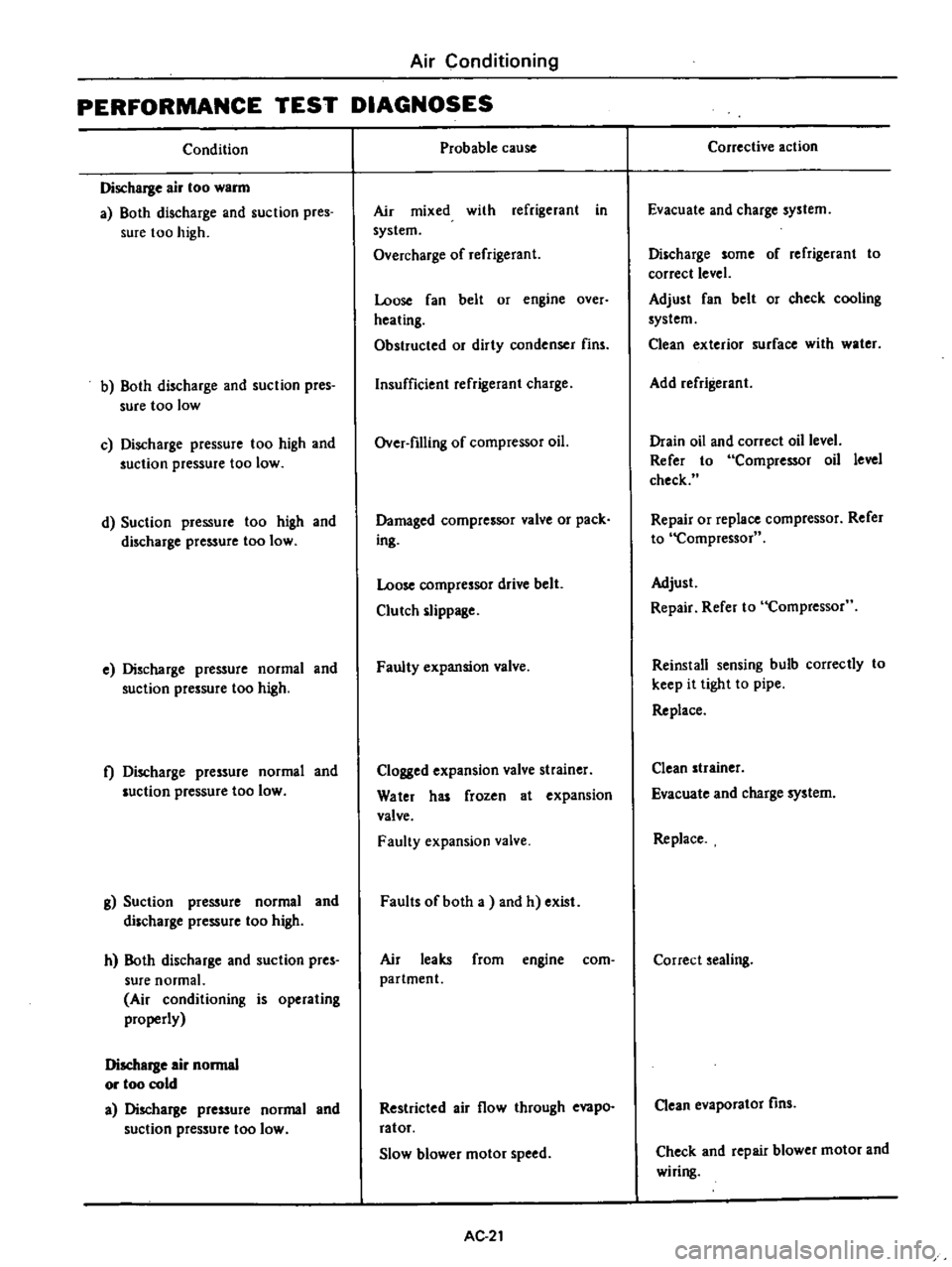
Air
Conditioning
PERFORMANCE
TEST
DIAGNOSES
Condition
Discharge
air
too
warm
a
Both
discharge
and
suction
pres
sure
too
high
b
Both
discharge
and
suction
pres
sure
too
low
c
Discharge
pressure
too
high
and
suction
pressure
too
low
d
Suction
pressure
too
high
and
discharge
pressure
too
low
e
Discharge
pressure
normal
and
suction
pressure
too
high
t
Discharge
pressure
normal
and
luction
pressure
too
low
g
Suction
pressure
normal
and
discharge
pressure
too
high
h
Both
discharge
and
suction
pres
sure
normal
Air
conditioning
is
operating
properly
Discharge
air
normal
or
too
cold
a
Discharge
pressure
normal
and
suction
pressure
too
low
Probable
cause
Air
mixed
with
refrigerant
in
system
Overcharge
of
refrigerant
Loose
fan
belt
or
engine
over
heating
Obstructed
or
dirty
condenser
fins
Insufficient
refrigerant
charge
Over
filling
of
compressor
oil
Damaged
compressor
valve
or
pack
ing
Loose
compressor
drive
belt
Clutch
slippage
Faulty
expansion
valve
Clogged
expansion
valve
strainer
Water
has
frozen
at
expansion
valve
Faulty
expansion
valve
Faults
of
both
a
and
h
exist
Air
leaks
from
engine
com
partment
Restricted
air
flow
through
evapo
ratof
Slow
blower
motor
speed
AC
21
Corrective
action
Evacuate
and
charge
system
Discharge
some
of
refrigerant
to
correct
level
Adjust
fan
belt
or
check
cooling
system
Clean
exterior
surface
with
water
Add
refrigerant
Drain
oil
and
correct
oil
level
Refer
to
Compressor
oil
level
check
Repair
or
replace
compressor
Refer
to
Compressor
Adjust
Repair
Refer
to
Compressor
Reinstall
sensing
bulb
correctly
to
keep
it
tight
to
pipe
Replace
Clean
strainer
Evacuate
and
charge
system
Replace
Correct
sealing
Clean
evaporator
fins
Check
and
repair
blower
motor
and
wiring
Page 511 of 537
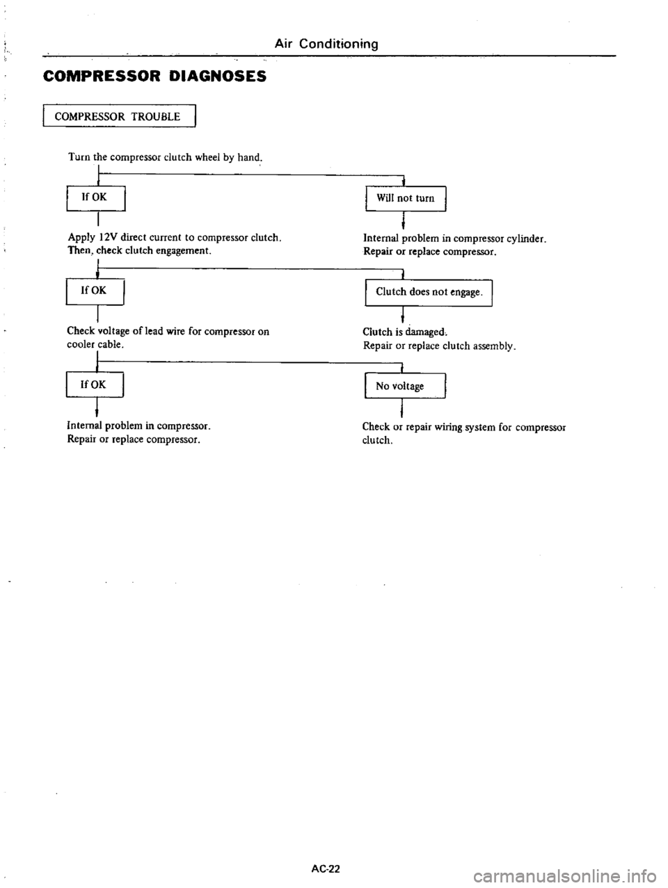
Air
Conditioning
COMPRESSOR
DIAGNOSES
I
COMPRESSOR
TROUBLE
Turn
the
compressor
dutch
wheel
by
hand
I
I
If
OK
j
Will
not
turn
Apply
12V
direct
current
to
compressor
clutch
Then
check
clutch
engagement
I
j
If
OK
I
Internal
problem
in
compressor
cylinder
Repair
or
replace
compressor
Check
voltage
oflead
wire
for
compressor
on
cooler
cable
I
I
If
OK
I
Clutch
does
not
engage
I
Clutch
is
damaged
Repair
or
replace
dutch
assembly
No
voltage
I
Internal
problem
in
compressor
Repair
or
replace
compressor
Check
or
repair
wiring
system
for
compressor
clutch
AC
22
Page 512 of 537
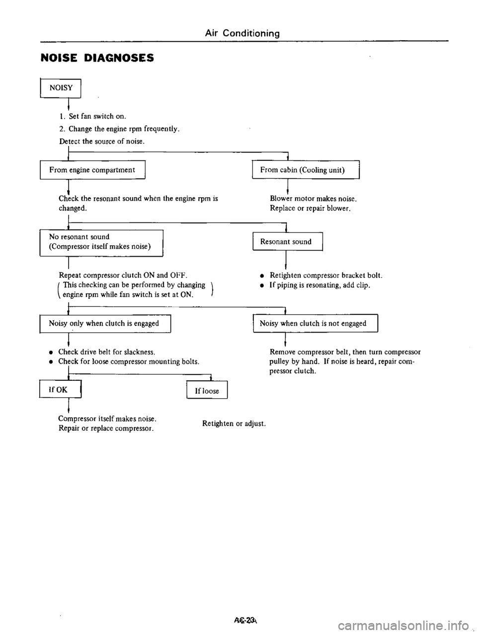
Air
Conditioning
NOISE
DIAGNOSES
NOISY
I
I
I
Set
fan
switch
on
2
Change
the
engine
rpm
frequently
Detect
the
source
of
noise
I
From
engine
compartment
From
cabin
Cooling
unit
j
Check
the
resonant
sound
when
the
engine
rpm
is
changed
I
I
No
resonant
sound
Compressor
itself
makes
noise
j
Blower
motor
makes
noise
Replace
or
repair
blower
Resonant
sound
Repeat
compressor
clutch
ON
and
OFF
This
checking
can
be
performed
by
changing
engine
rpm
while
fan
switch
is
set
at
ON
Retighten
compressor
bracket
bolt
If
piping
is
resonating
add
clip
Noisy
only
when
clutch
is
engaged
Noisy
when
clutch
is
not
engaged
I
Check
drive
belt
for
slackness
Check
for
loose
compressor
mounting
bolts
I
I
Remove
compressor
belt
then
turn
compressor
pulley
by
hand
If
noise
is
heard
repair
com
pressor
clutch
If
OK
If
loose
Compressor
itself
makes
noise
Repair
or
replace
compressor
Retighten
or
adjust
Nl1