clutch DATSUN PICK-UP 1977 Owners Manual
[x] Cancel search | Manufacturer: DATSUN, Model Year: 1977, Model line: PICK-UP, Model: DATSUN PICK-UP 1977Pages: 537, PDF Size: 35.48 MB
Page 522 of 537
DESCR
IPTIDN
COMPRESSOR
CLUTCH
REMOVAL
INSTAllATION
DISASSEMBLY
ASSEMBLY
INSPECTION
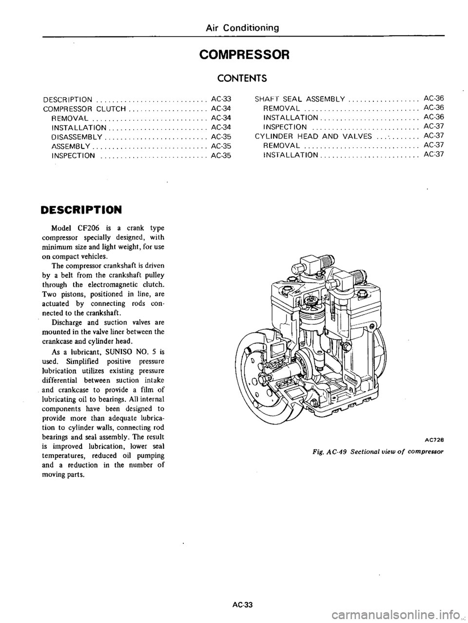
DESCRIPTION
Model
CF206
is
a
crank
type
compressor
specially
designed
with
minimum
size
and
light
weight
for
use
on
compact
vehicles
The
compressor
crankshaft
is
driven
by
a
belt
from
the
crankshaft
pulley
through
the
electromagnetic
clutch
Two
pistons
positioned
in
line
are
actuated
by
connecting
rods
coo
nected
to
the
crankshaft
Discharge
and
suction
valves
are
mounted
in
the
valve
liner
between
the
crankcase
and
cylinder
head
As
a
lubricant
SUNlSO
NO
5
is
used
Simplified
positive
pressure
lubrication
utilizes
existing
pressure
differential
between
suction
intake
and
crankcase
to
provide
a
film
of
lubricating
oil
to
bearings
All
internal
components
have
been
designed
to
provide
more
than
adequate
lubrica
tion
to
cylinder
walls
connecting
rod
bearings
and
seal
assembly
The
result
is
improved
lubrication
lower
seal
temperatures
reduced
oil
pumping
and
a
reduction
in
the
number
of
moving
parts
Air
Conditioning
COMPRESSOR
AC33
AC34
AC34
AC34
AC35
AC
35
AC35
CONTENTS
SHAFT
SEAL
ASSEMBLY
REMOVAL
INSTAllATION
INSPECTION
CYLINDER
HEAD
AND
VALVES
REMOVAL
INSTAllATION
AC36
AC36
AC36
AC37
AC37
AC37
AC37
AC728
Fig
AC
49
Sectional
view
of
compressor
AC33
Page 523 of 537
Air
Conditioning
1foo
1t
1
t7
LV
I
1
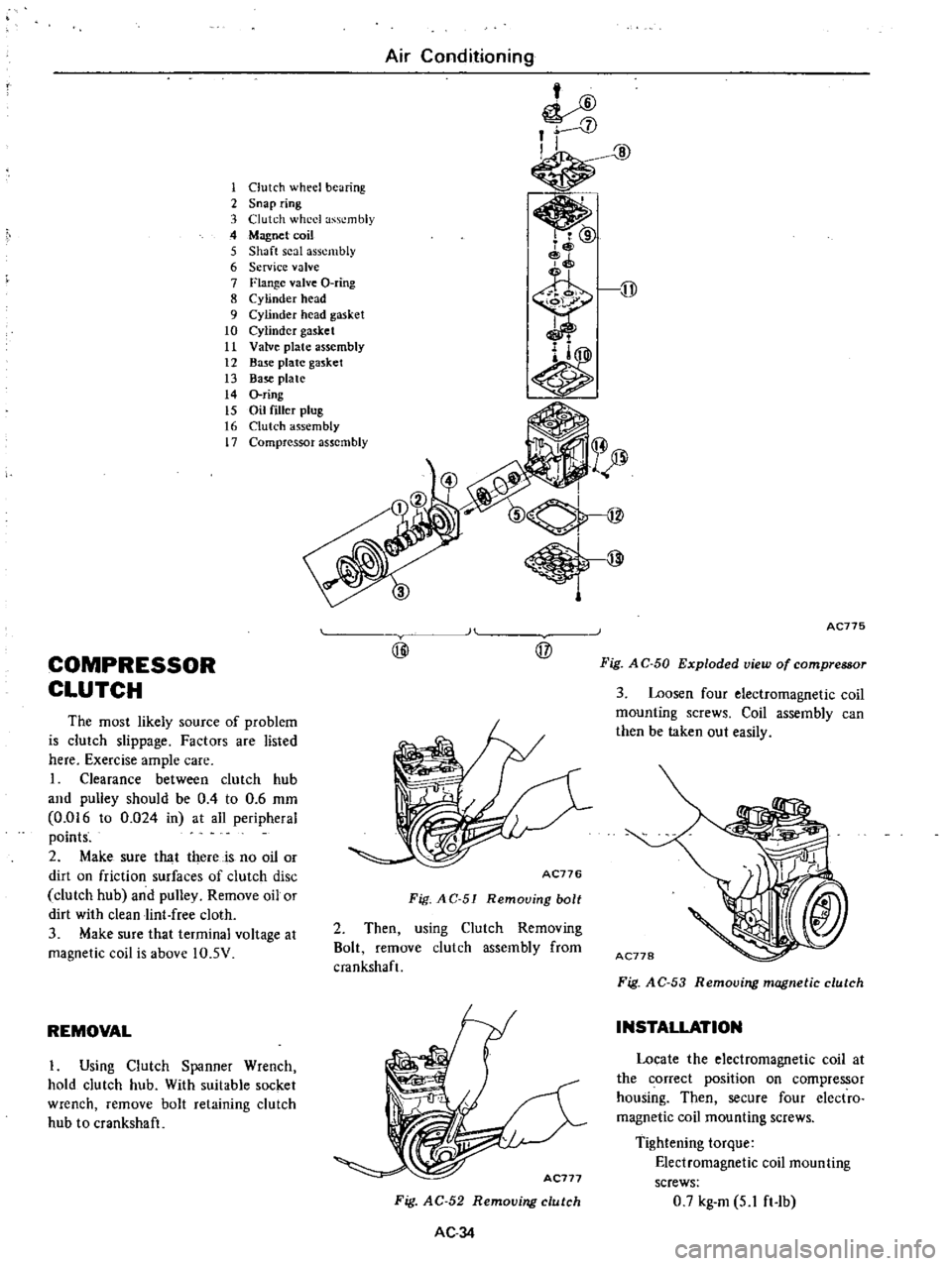
Clutch
wheel
bearing
2
Snap
ring
3
Clutch
wheel
assembly
4
Magnet
coil
5
Shaft
seal
assembly
6
Service
valve
7
Flange
valve
O
ring
8
Cylinder
head
9
Cylinder
head
gasket
10
Cylinder
gasket
11
Valve
plate
assembly
12
Base
plate
gasket
13
Base
plate
14
O
ring
15
Oil
filler
plug
16
Clutch
assembly
17
Compressor
assembly
COMPRESSOR
CLUTCH
The
most
likely
source
of
problem
is
clutch
slippage
Factors
are
listed
here
Exercise
ample
care
I
Clearance
between
clutch
hub
and
pulley
should
be
0
4
to
0
6
mm
0
016
to
0
024
in
at
all
peripheral
points
2
Make
sure
that
there
is
no
oil
or
dirt
on
friction
surfaces
of
clutch
disc
clutch
hub
and
pulley
Remove
oil
or
dirt
with
clean
lint
free
cloth
3
Make
sure
that
terminal
voltage
at
magnetic
coil
is
above
IO
5V
REMOVAL
I
Using
Clutch
Spanner
Wrench
hold
clutch
hub
With
suitable
socket
wrench
remove
bolt
retaining
clutch
hub
to
crankshaft
H
@
@
AC776
Fig
AC
51
Remouing
bolt
2
Then
using
Clutch
Removing
Bolt
remove
clutch
assembly
from
cmnkshaft
Fig
AC
52
Removing
clutch
AC34
AC775
Fig
A
C
50
Exploded
view
of
compressor
3
Loosen
four
electromagnetic
coil
mounting
screws
Coil
assembly
can
then
be
taken
out
easily
Fig
A
C
53
Removing
magnetic
clutch
INSTALLATION
Locate
the
electromagnetic
coil
at
the
correct
position
on
compressor
housing
Then
secure
four
electro
magnetic
coil
mounting
screws
Tightening
torque
Electromagnetic
coil
mounting
screws
0
7
kg
m
5
1
ft
Ib
Page 524 of 537
2
Install
the
clutch
assembly
on
the
crankshaft
Note
Key
should
be
set
on
crank
shaft
before
installing
clutch
assem
bly
3
Using
Clutch
Spanner
Wrench
hold
clutch
hub
With
socket
wrench
secure
clutch
hub
securing
bolt
Tightening
torque
Clutch
hub
securing
bolt
1
5
kg
m
II
ft
lb
DISASSEMBLY
1
Remove
two
snap
rings
retaining
bearing
They
are
located
inside
of
clutch
wheel
AC500
Fig
AC
54
Removing
snap
rings
2
Using
Clutch
Wheel
Remover
KV99100700
and
conventional
puller
remove
V
pulley
with
bearings
from
clutch
wheel
KV99100700
AC501
Fig
A
C
55
Removing
clutch
wheel
bearings
3
Using
Bearing
Remover
ST33061000
press
clutch
wheel
bear
ings
out
from
clutch
wheel
Air
Conditioning
9
AC502
Fig
AC
56
Removing
V
pulley
from
clutch
ASSEMBLY
I
Press
bearings
into
V
pulley
with
Bearing
Installer
ST02371000
ST02371000
AC503
Fig
A
C
57
Installing
bearin
2
Install
outer
snap
ring
in
groove
of
V
pulley
3
Using
Installer
KV99100610
and
Stopper
ST33061000
press
clutch
wheel
into
V
pulley
4
Install
inner
snap
ring
in
groove
of
clutch
wheel
t
INSPECTION
Check
friction
surface
of
clutch
for
damage
due
to
excessive
heat
or
excessive
grooving
due
to
slippage
If
necessary
replace
clutch
wheel
and
V
pulley
as
a
set
2
The
clearance
between
V
pulley
and
clutch
wheel
should
be
0
4
to
0
6
mm
0
016
to
0
024
in
If
not
replace
clutch
wheel
assem
bly
AC
35
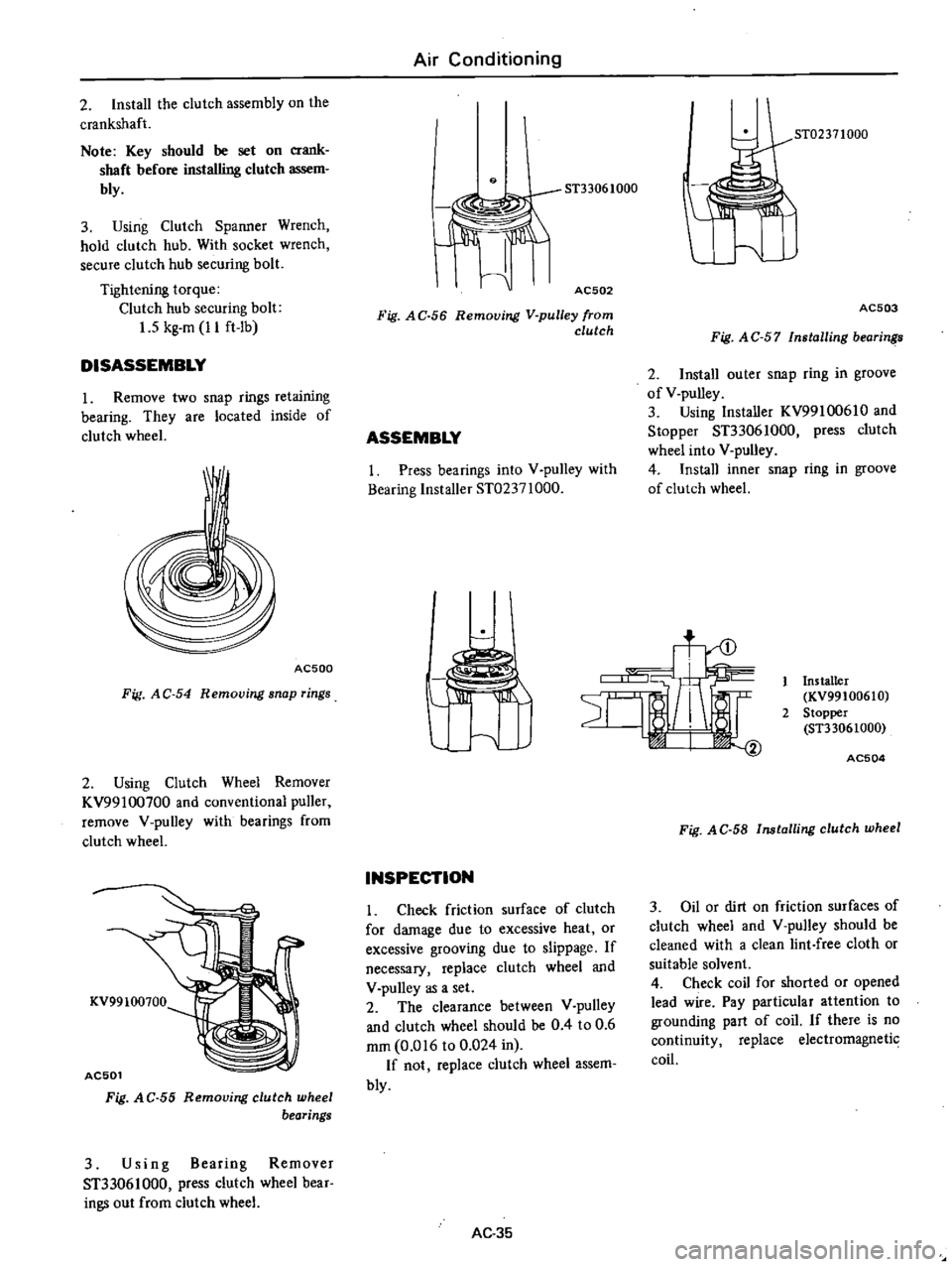
Installer
KV99100610
2
Stopper
ST33061000
AC504
Fig
AC
58
Installing
clutch
wheel
3
Oil
or
dirt
on
friction
surfaces
of
clutch
wheel
and
V
pulley
should
be
cleaned
with
a
clean
lint
free
cloth
or
suitable
solvent
4
Check
coil
for
shorted
or
opened
lead
wire
Pay
particular
attention
to
grounding
part
of
coil
If
there
is
no
continuity
replace
electromagnetic
coil
Page 525 of 537
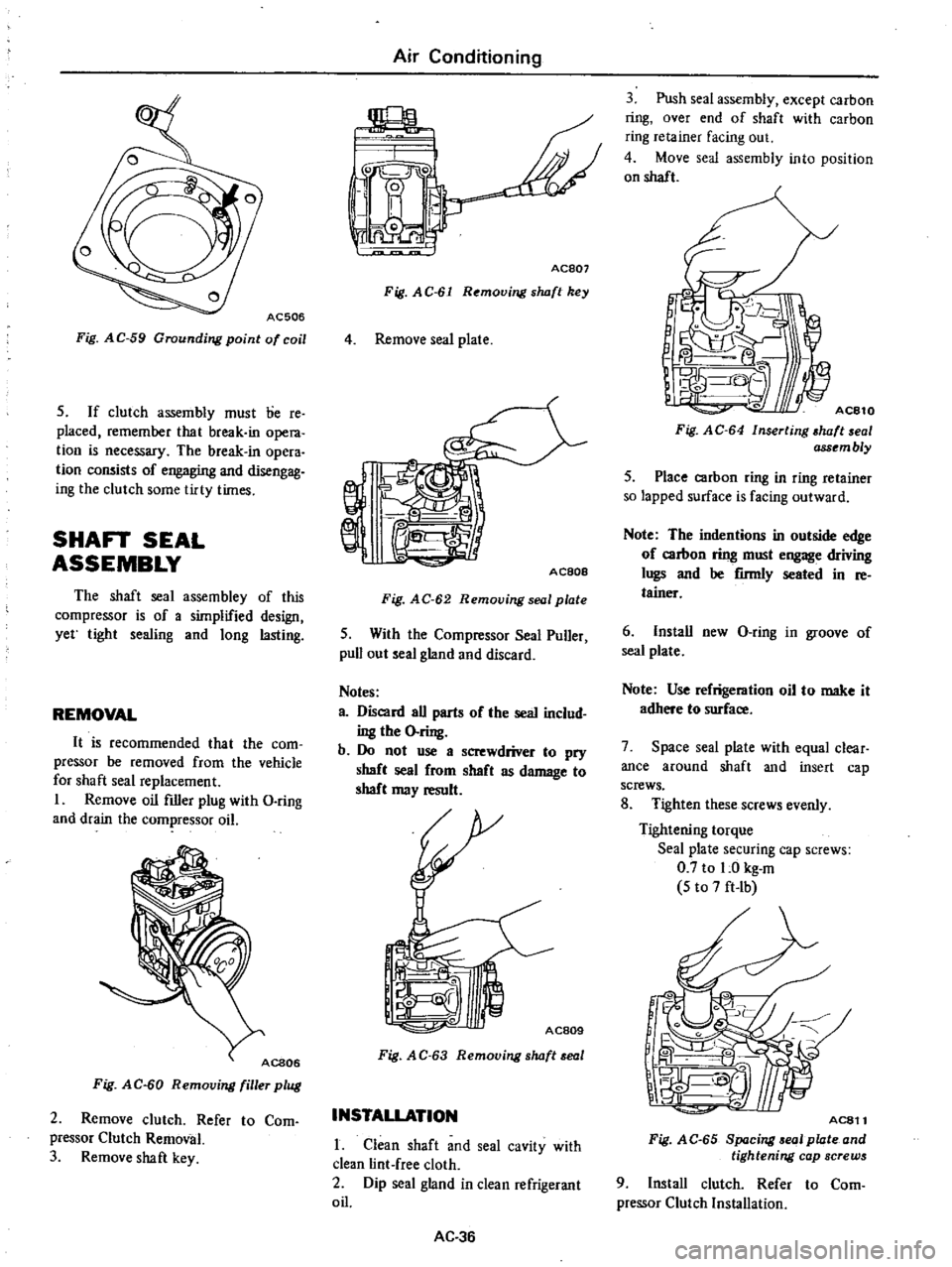
AC506
Fig
AC
59
Grounding
point
of
coil
5
If
clutch
assembly
must
lie
re
placed
remember
that
break
in
opera
tion
is
necessary
The
break
in
opera
tion
consists
of
engaging
and
disengag
ing
the
clutch
some
tirty
times
SHAFT
SEAL
ASSEMBLY
The
shaft
seal
assembley
of
this
compressor
is
of
a
simplified
design
yet
tight
sealing
and
long
lasting
REMOVAL
It
is
recommended
that
the
com
pressor
be
removed
from
the
vehicle
for
shaft
seal
replacement
I
Remove
oil
filler
plug
with
D
ring
and
drain
the
compressor
oil
Fig
AC
60
Removing
filler
plug
2
Remove
clutch
Refer
to
Com
pressor
Clutch
Removal
3
Remove
shaft
key
Air
Conditioning
jpL
Y
L
I
i
0
I
I
0
Ace07
Fig
AC
61
Removing
s
wft
key
4
Remove
seal
plate
AC80e
Fig
AC
62
Removing
seal
plate
5
With
the
Compressor
Seal
Puller
pull
out
seal
gland
and
discard
Notes
a
Discard
all
parts
of
the
seal
includ
ing
the
O
ring
b
Do
not
use
a
screwdriver
to
pry
shaft
seal
from
shaft
as
damage
to
shaft
may
result
AC809
Fig
A
C
63
Removing
s
wft
eal
INSTALLATION
1
Clean
shaft
and
seal
cavity
with
clean
lint
free
cloth
2
Dip
seal
gland
in
clean
refrigerant
oil
AC
36
3
Push
seal
assembly
except
carbon
ring
over
end
of
shaft
with
carbon
ring
retainer
facing
out
4
Move
seal
assembly
into
position
on
shaft
1
I
Fig
AC
64
Inserting
wft
al
ass
mbly
5
Place
carbon
ring
in
ring
retainer
so
lapped
surface
is
facing
outward
Note
The
indentions
in
outside
edge
of
carbon
ring
must
engage
driving
lugs
and
be
firmly
seated
in
re
tainer
6
Install
new
D
ring
in
groove
of
seal
plate
Note
Use
refrigeration
oil
to
make
it
adhere
to
surface
7
Space
seal
plate
with
equal
clear
ance
around
shaft
and
insert
cap
screws
8
Tighten
these
screws
evenly
Tightening
torque
Seal
plate
securing
cap
screws
0
7
to
1
0
kg
m
5
to
7
ft
Ib
AC811
Fig
AC
65
8p
cing
01
plate
and
tightening
cap
screws
9
Install
clutch
Refer
to
Com
pressor
Clutch
Installation
Page 528 of 537

Air
Conditioning
SPECIAL
SERVI
CE
TOOLS
Unit
mm
in
For
use
on
Reference
page
or
Figure
No
No
Tool
number
tool
name
Description
KV99100700
Clutch
wheel
remover
To
remove
clutch
wheel
from
V
pulley
620
Fig
AC
55
BE436
2
KV991006S0
To
install
clutch
wheel
into
V
pulley
620
Fig
AC
58
Clutch
wheel
38
1
50
1
installer
set
KV99100610
Installer
ST33061000
Stopper
BE437
3
ST33061000
To
remove
clutch
wheel
bearing
from
V
pulley
620
Fig
AC
56
Bearing
remover
38
1
50
BE438
4
ST02371000
To
install
clutch
wheel
bearing
into
V
pulley
620
Fig
AC
57
Bearing
installer
50
1
96
Co
tJ
BE439
AC
39
Page 529 of 537
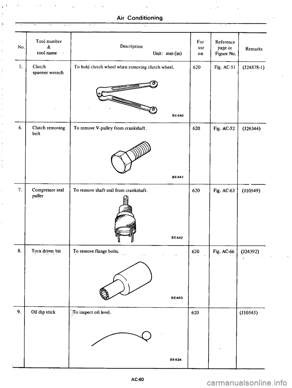
Air
Conditioning
Tool
number
For
Reference
No
Description
use
page
or
Remarks
tool
name
Unit
mm
in
on
Figure
No
5
Clutch
To
hold
clutch
wheel
when
removing
clurch
wheel
620
Fig
AC
51
124878
1
spanner
wrench
6
Clutch
removing
bolt
7
Compressor
seal
puller
8
Torx
driver
bit
9
Oil
dip
stick
To
remove
V
pulley
from
crankshaft
To
remove
shaft
seal
from
crankshaft
To
remove
flange
bolts
To
inspect
oil
level
AC
40
BE440
BE441
BE442
B
E443
BE434
620
620
620
620
Fig
AC
52
126344
Fig
AC
63
J
10549
Fig
AC
66
124392
110545
Page 533 of 537

Service
Equipment
CHAssis
AND
BODY
TOOL
Applied
Ser
17
620NA
No
Tool
Number
Tool
Name
vehic
1e
Newly
Class
Remarks
added
or
unit
KYOO
1
02000
Clutch
5Tl
66
1000
I
Pilot
bushing
puller
All
X
3
610
710
530
KV30100200
Clutch
aligning
bar
All
X
2
610
710
530
5T200500
10
Base
plate
All
X
5
B210
610
710
530
5T20050100
Distance
piece
All
X
5
B210
610
710
530
5T20050051
5et
bolt
All
X
5
B210
610
710
530
5TZ0050240
Diaphragm
adjusting
wrench
All
X
5
B210
610
710
530
GG943
10000
Flare
nut
torque
wrench
All
X
2
FIO
B210
610
710
530
2
Manual
transmission
5TZ2360002
DriftC
All
X
2
B21O
530
5T23540000
Fork
rod
pin
punch
All
X
2
FIO
B210
610
710
530
5T23800000
Transmission
adapter
All
X
2
FIO
B210
610
710
530
5T23810001
5etting
plate
adapter
All
X
5
530
5T22520000
Wrench
All
X
2
B2iO
530
5T23860000
Counter
gear
drift
All
X
2
530
KV311
00400
Transmission
press
stand
All
X
5
530
5T30031000
Bearing
puller
All
X
2
FIO
B210
610
710
530
KV32101330
Bearing
puller
FSSW71B
X
X
2
B21O
530
3
Differential
ST063
I
0000
Diff
attachment
All
X
5
610
ST31530000
Drive
pinion
flange
wrench
All
X
2
B210
610
710
S30
ST3306S001
Diff
side
bearing
puller
All
X
2
610
S30
ST33051001
Puller
ST3306
I
000
Adapter
ST3090S000
Orive
pinion
rear
bearing
inner
race
All
X
2
610
S30
replacer
ST30031000
Puller
ST3090
1000
Base
ST33230000
Diff
side
bearing
drift
All
X
2
610
ST3194S000
Drive
pinion
setting
gauge
ass
y
All
X
2
610
ST3l941000
Height
gauge
5T3l942000
Dummy
shaft
SE
4
Page 535 of 537

Service
Equipment
AUTOMATIC
TRANSMISSION
TOOL
Applied
Set
3N71B
Newly
Tool
Number
Tool
Name
vehicle
Class
Remarks
added
or
unit
KVOOlO1OOO
ST07870000
Transmission
case
stand
All
X
3
ST2505S001
Oil
pressure
gauge
set
All
X
I
ST25
I
60000
Torque
driver
All
X
3
ST2532000l
Snap
ring
remover
All
X
3
ST25420001
Clutch
spring
compressor
All
X
3
ST25490000
Socket
extension
All
X
3
ST2557000l
Hex
head
extension
All
X
3
8210
610
710
S30
ST25580000
Oil
pump
assembling
gauge
All
X
3
ST25850000
Sliding
hammers
All
X
3
GG930
I
0000
Torque
wrench
All
X
3
HT6
I
000800
Hexagon
wrench
All
X
3
HT62350000
Spinner
handle
All
X
6
HT69860000
Snap
ring
remover
All
X
3
SE
6