ABS DATSUN PICK-UP 1977 Service Manual
[x] Cancel search | Manufacturer: DATSUN, Model Year: 1977, Model line: PICK-UP, Model: DATSUN PICK-UP 1977Pages: 537, PDF Size: 35.48 MB
Page 3 of 537
FOREWORD
This
service
manual
has
been
prepared
for
the
purpose
of
assisting
service
personnel
of
authorized
NISSAN
DATSUN
dealers
fu
providing
effective
service
and
maintenance
of
the
1977
Datsun
Pick
up
Since
proper
maintenance
and
service
are
absolutely
essential
fu
satisfying
the
Datsun
owners
this
inan
la1
should
be
kept
fu
a
handy
place
for
ready
reference
and
should
be
carefuny
studied
This
man
la1
fucludes
procedures
for
ma
futenance
ac
1justrnents
minor
service
operations
remowl
and
installation
and
for
disassembly
and
assembly
of
components
Some
of
these
service
operations
require
the
use
of
Special
Tools
especially
designed
for
effectiveperfonnance
of
service
operations
The
special
tools
are
presented
in
the
SE
section
As
you
read
through
the
maintenance
procedures
in
this
service
manual
you
will
occasionally
corne
across
paragraphs
headed
NOTE
or
CAUTION
A
NOTE
is
supplemental
infortl1ation
that
is
important
to
B
particular
procedure
CAUTION
warns
of
steps
that
must
be
fonowed
to
prevent
personal
injury
and
Qr
damage
to
some
part
of
your
DATSUN
The
Quick
Reference
Index
on
the
first
page
enables
the
user
to
quickly
locate
the
desired
section
At
the
beginning
of
each
individual
section
is
a
table
of
contents
which
gives
the
page
number
on
which
each
major
subject
begins
An
index
is
placed
at
the
beginning
of
each
major
subject
within
the
section
All
information
illustrations
and
specifications
contained
in
this
manual
are
based
on
the
latest
product
information
available
at
the
time
of
publication
approval
If
YOUT
DATSUN
model
differs
from
the
specifications
contained
in
this
manual
consult
your
NlSSAN
DATSUN
dealer
for
information
Rights
for
alteratiohat
any
time
of
specifications
and
methods
are
reserved
liability
for
any
personal
injury
or
property
damage
occasioned
by
the
use
of
this
service
man
la1
in
effecting
maintenance
or
repair
of
your
Datsun
is
in
no
way
assumed
by
Nissan
M9tor
Co
Ltd
Accordingly
anyone
using
a
service
procedure
or
tool
which
is
not
specifically
w
mended
by
Nissan
must
fust
completely
satisfy
himself
that
neither
his
safety
nor
the
vehicle
s
safety
wi11be
jeopardized
by
the
service
method
selected
NISSAN
MOTOR
CO
LTD
TOKYO
JAPAN
@
1976
N1SSAN
MOTOR
CO
LTD
Printed
in
Japan
Page 163 of 537

3
Check
ignition
system
with
regard
to
the
following
items
Refer
to
Inspection
of
Ignition
System
1
Ignition
AMP
2
Distributor
Emission
Control
System
3
Ignition
coil
4
High
tension
code
5
Spark
plug
4
Check
idle
CO
adjustment
Refer
to
Inspection
of
Idle
CO
Adjustment
Note
Even
if
there
is
nothing
wrong
with
engine
the
warning
lamp
may
come
on
if
vebicle
is
being
driven
on
a
steep
slope
continuously
in
lower
gears
at
high
engine
speeds
EVAPORATIVE
EMISSION
CONTROL
SYSTEM
CONTENTS
DESCRIPTION
OPERATION
INSPECTION
FUEL
TANK
VAPOR
LIQUID
SEPARATOR
AND
VAPOR
VENT
LINE
DESCRIPTION
The
evaporative
emission
control
system
is
used
to
reduce
hydrocarbons
emitted
to
the
atmosphere
from
the
fuel
system
This
reduction
of
hydro
EC
30
EC
30
EC
31
CARBON
CANISTER
PURGE
CONTROL
VALVE
CARBON
CANISTER
FILTER
FUEL
TANK
VACUUM
RELIEF
VALVE
IEC
32
IEC
32
EC
32
EC
31
carbons
is
accomplished
by
activated
charcoals
in
the
carbon
canister
This
system
is
made
up
to
the
following
I
Fuel
tank
with
positive
sealing
filler
cap
@
2
Vapor
liquid
separator
3
Vapor
vent
line
4
Carbon
canister
5
Vacuum
signal
line
6
Canister
purge
line
5
OPERATION
Fuel
vapors
from
the
sealed
fuel
tank
are
led
into
the
carbon
canister
1
Fuel
tank
2
Fuel
nIler
cap
with
vacuum
relief
valve
3
liquid
vapor
separator
4
Vapor
vent
line
5
Canister
purge
line
6
Vacuum
signal
line
7
Carbon
canister
EF274
Fig
EC
76
Schematic
drawing
of
l
Iaporotive
emiaion
control6ydem
The
canister
is
fined
with
activated
charcoals
to
absorb
the
fuel
vapors
EC
30
when
the
engirie
is
at
rest
or
at
idlin
ll
See
Figure
EC
77
Page 232 of 537
Condition
Clutch
chatters
Noisy
clutch
Clutch
grabs
CLUTCH
Probable
cause
and
testing
Corrective
action
Clutch
chattering
is
usually
noticeable
when
vchicle
is
just
rolled
off
with
clutch
partially
engaged
Weak
or
broken
clutch
disc
torsion
spring
Oil
or
grease
on
clutch
facing
Clutch
facing
out
of
proper
contact
or
clutch
disc
runout
Loose
rivets
Warped
pressure
plate
or
clutch
cover
surface
Unevenness
of
diaphragm
spring
toe
height
Loose
engine
mounting
or
deteriorated
rubber
A
noise
is
heard
after
clutch
is
disengaged
Damaged
release
bearing
A
noise
is
heard
when
clutch
is
disengaged
Insufficient
grease
on
the
sliding
surface
of
bearing
sleeve
Clutch
cover
and
bearing
are
not
installed
correctly
Replace
Replace
Replace
Replace
Repair
or
replace
Adjust
or
replace
Retighten
or
replace
I
Replace
Apply
grease
Adjust
A
noise
is
heard
when
vehicle
is
suddei11y
staited
off
with
clutch
partially
engaged
Damaged
pilot
bushing
I
Replace
When
grabbing
of
clutch
occurs
vehicle
will
not
start
off
smoothly
from
a
standing
start
or
clutch
is
engaged
before
clutch
pedal
is
fully
depressed
Oil
or
grease
on
clutch
facing
Clutch
facing
worn
or
loose
rivets
Wear
or
rust
on
splines
in
drive
shaft
and
clu
tch
disc
Warped
flywheel
or
pressure
plate
Loose
mountings
for
engine
or
power
train
units
CLll
Replace
Replace
Clean
or
replace
Repair
or
replace
Retighten
Page 276 of 537

R
RANGE
REVERSE
In
R
range
the
front
clutch
and
the
low
and
reverse
brake
are
applied
The
power
flow
is
through
the
input
shaft
front
clutch
and
connecting
shell
to
the
sun
gear
Clockwise
rota
tion
of
the
sun
gear
causes
counter
clockwise
rotation
of
the
rear
planeta
ry
gears
With
the
connecting
drum
held
stationary
by
the
low
and
reverse
brake
the
rear
planetary
gears
rotate
the
rear
internal
gear
and
drive
the
flange
counterclockwise
The
rear
drive
flange
splined
to
the
output
shaft
rotates
the
output
shaft
counterclock
wise
at
a
reduced
speed
with
an
increase
in
torque
for
reverse
gear
Automatic
Transmission
R
Fig
AT
26
Power
tranamis
ion
during
R
range
m
i
1
A
TOBS
Fig
A
T
21
Optrationof
each
mechanism
during
R
range
When
the
manual
valve
V
is
posi
Clutch
Low
Band
servo
One
tioned
at
R
range
the
oil
having
the
Gear
Partina
Ranae
re
ne
way
line
pressure
7
is
directed
to
line
ralio
Front
Rear
brake
Openlion
Relulie
clutch
plwl
pressure
circuits
5
and
6
The
pressure
in
the
circuit
5
actuates
the
Park
on
on
low
and
reverse
brake
after
being
Ruene
2
182
on
on
on
introduced
into
line
pressure
circuit
Neutral
12
through
the
I
st
2nd
shift
valve
ID
The
pressure
in
the
circuit
op
DI
Low
2
458
on
on
erates
the
release
side
of
the
band
servo
and
the
front
c1u
tch
after
being
Driowe
D2
Second
1
458
on
on
led
to
line
pressure
circuit
0
D3
Top
1
000
on
on
on
through
the
2nd
3rd
shift
valve
@
2
Second
1
458
The
throttle
pressure
I
6
and
the
line
on
on
pressure
6
which
vary
with
the
12
Second
S8
on
on
degree
of
accelerator
pedal
depression
II
Low
2
458
both
act
the
pressure
regulator
on
on
on
valve
CD
and
press
against
its
valve
CD
increasing
line
pressure
7
In
Rn
range
the
governor
pressure
is
absent
making
all
such
valves
as
the
1st
2nd
shift
valve
ID
lnd
3rd
shift
valvc
@
and
pressurc
modifier
valve
inoperative
AT16
Page 280 of 537

Automatic
Transmission
R
RANGE
REVERSE
R
In
R
range
the
front
dutch
and
the
low
and
reverse
brake
are
applied
The
power
flow
is
through
the
input
shaft
front
clutch
and
connecting
shell
to
the
sun
gear
Clockwise
rota
tion
of
the
sun
gear
causes
counter
clockwise
rotation
of
the
rear
planeta
ry
gears
With
the
connecting
drum
held
Slationary
by
the
low
and
reverse
brake
the
rear
planetary
gears
rotate
the
rear
internal
gear
and
drive
the
flange
counterclockwise
The
rear
drive
flange
splined
to
the
output
shaft
rotates
the
output
shaft
counterclock
wise
at
a
reduced
speed
with
an
increase
in
torque
for
reverse
gear
f
When
Ihe
manual
valve
CV
is
posi
tioned
at
R
range
Ihe
oil
having
Ihe
line
pressure
7
is
directed
to
line
pressure
circuits
5
and
6
The
pressure
in
the
circuit
5
actuates
the
low
and
reverse
brake
after
being
introduced
into
line
pressure
circuit
12
through
the
I
st
2nd
shift
valve
@
The
pressure
in
Ihe
circuit
op
erates
the
release
side
of
the
band
servo
and
the
front
clutch
after
being
led
to
line
pressure
circuit
10
through
the
2nd
3rd
shift
valve
@
The
throtlle
pressure
16
and
the
line
pressure
6
which
vary
with
the
degree
of
acceJerator
pedal
depression
both
act
on
the
prcssure
regulator
valve
CD
and
press
against
its
valve
CD
increasing
line
pressure
7
In
R
range
the
governor
pressure
is
absent
making
all
slldl
valves
as
the
J
SI
2nd
shift
valve
@
2nd
3rd
shift
valvc
@
and
pressure
modifier
valve
j
inoperative
C
Fig
AT
26
Power
transmi
ion
during
R
range
A
TOS5
Fig
AT
27
Operation
attach
mechanism
during
R
range
G
Clutch
Low
A
Band
servo
One
Parkin
Ran
no
wa
plwl
ratio
Front
Rear
brake
Operllioo
Rdr
ue
clutch
k
on
on
Revctte
1
181
on
on
on
Neutnl
DI
Low
1
418
on
on
Driw
D2
Second
1
458
on
on
DJ
Top
1
000
on
on
on
on
2
Second
1
458
on
on
12
Second
1
458
on
on
I
II
Low
2
458
on
on
AT
16
Page 317 of 537
Automatic
Transmission
LINE
PRESSURE
GOVERNOR
FEED
PRESSURE
At
cut
back
point
After
cut
back
Throttle
opening
under
approximately
over
approximately
15
kmfh
10
MPH
35
kmfh
22
MPH
Unit
mmHg
Unit
kgfcm2
psi
Unit
kgfcm2
psi
Full
throtlle
0
9
4
to
11
0
134
to
156
5
5
to
6
5
78
to
92
Minill1um
throttle
450
3
0
to
4
0
43to
57
3
0
to
4
0
43
to
57
Fulllhrotlle
0
10
0
to
12
0
142
to
171
5
5
to
7
0
78
to
100
Minimum
throttle
450
6
0
to
12
0
85to171
5
5
to
7
0
78
to
100
Full
throtlle
0
14
0
to
16
0
199
to
228
14
0
to
16
0
199
to
228
Minimum
throttle
450
3
0
to
5
5
43
to
78
3
0
to
5
5
4
lo
78
Range
D
2
R
Notes
a
The
line
pressure
during
idling
corresponds
to
the
oil
pressure
before
cut
down
at
minimum
throttle
b
The
oil
pressure
After
cut
back
means
that
after
the
pressure
modifier
valve
has
operated
JUDGEMENT
IN
MEASURING
LINE
PRESSURE
Low
idling
line
pressure
in
the
ranges
D
2
I
R
and
pH
This
can
be
atlributed
to
trouble
in
the
pressure
supply
system
or
too
low
output
of
power
caused
by
I
A
worn
oil
pump
2
An
oil
pressure
leak
in
the
oil
pump
valve
body
or
case
3
A
sticking
regulator
valve
2
Low
idling
line
pressure
in
cer
tain
ranges
only
This
is
presumably
caused
by
an
oil
leak
in
the
devices
or
circuits
con
nected
to
the
relevant
ranges
I
When
there
is
an
oil
leak
in
the
rear
clutch
and
governor
the
line
pressure
in
D
2
and
I
are
low
but
the
pressure
is
norrrial
in
R
2
When
an
oil
leak
occurs
in
the
low
and
reverse
brake
circuit
the
line
pressure
in
R
and
P
are
low
but
the
pressure
is
normal
in
D
2
and
I
3
High
idling
line
pressure
This
is
presumably
caused
by
an
increased
vacuum
throttle
pressure
owing
to
a
leak
in
the
vacuum
tube
or
dia
phragm
or
by
an
increased
line
pressure
due
to
a
sticking
regulator
valve
Vacuum
leakage
is
checked
by
directly
measuring
the
negative
pres
sure
after
removing
the
vacuum
pipe
A
puncture
of
the
vacuum
dia
phragm
can
be
easily
ascertained
because
the
torque
converter
oil
is
absorbed
into
the
engine
and
the
exhaust
pipe
emits
white
smoke
4
Items
to
be
checked
when
the
line
pressure
is
increasing
In
this
check
the
line
pressure
should
be
measured
with
vacuums
of
450
mmHg
and
0
mmHg
in
accordance
with
the
stall
test
procedure
I
If
the
line
pressure
do
not
n
crease
despite
the
vacuum
decrease
check
whether
the
vacuum
rod
is
incorporated
2
If
the
line
pressure
do
not
meet
the
standard
it
is
caused
mostly
by
a
sticking
pressure
regulating
valve
pres
sure
regulating
valve
plug
or
amplifier
TROUBLE
SHOOTING
CHART
INSPECTING
ITEMS
1
Inspection
with
automatic
trans
mission
on
vehicle
AT
53
A
Oil
level
B
Ra
lge
select
linkage
C
Inhibitor
switch
and
wiring
D
Vacuum
diaphragm
and
piping
E
Downshift
solenoid
kickdown
switch
and
wiring
F
Engine
idling
rpm
G
Oil
pressure
throttle
H
Engine
stall
rpm
I
Rear
lubrication
J
Control
valve
manual
K
Governor
valve
L
Band
servo
M
Transmission
air
check
N
Oil
quantity
o
Ignition
switch
and
starter
motor
P
Engine
adjustment
and
brake
in
spection
2
Inspection
after
inspecting
auto
matic
transmission
on
vehicle
m
Rear
clutch
n
Front
clutch
q
Band
brake
r
Low
and
reverse
brake
s
Oil
pump
t
Leakage
of
oil
passage
u
One
way
clutch
of
troque
coilVerter
v
One
way
clutch
of
transmission
w
Front
clutch
check
ball
x
Parking
linkage
y
Planetary
gear
Page 351 of 537
Front
Axle
Front
Suspension
FRONT
AXLE
AND
FRONT
SUSPENSION
CONTENTS
GENERAL
DESCRIPTION
FRONT
AXLE
REMOVAL
AND
INSTALLATION
WHEEL
BEARING
ADJUSTMENT
DISASSEMBLY
AND
ASSEMBLY
INSPECTION
SHOCK
ABSORBER
REMOVAL
AND
INSTALLATION
INSPECTION
STABILIZER
REMOVAL
AND
INSTALLATION
INSPECTION
TENSION
ROD
FA
2
FA
3
FA
3
FA
4
FA
4
FA
5
FA
8
FA
8
FA
8
FA
8
FA
8
FA
8
FA
8
REMOVAL
AND
INSTALLATION
INSPECTION
TORSION
BAR
SPRING
REMOVAL
AND
INSTALLATION
INSPECTION
UPPER
AND
LOWER
LINKS
FjEMOVAL
AND
INSTALLATION
DISASSEMBLY
AND
ASSEMBLY
INSPECTION
ADJUSTMENT
VEHICLE
POSTURE
WHEEL
ALIGNMENT
STEERING
ANGLE
GENERAL
DESCRIPTION
uUl
FA
8
FA
9
FA
9
FA
9
FA
9
FA
10
FA
l0
FA
ll
FA
ll
FA
Il
FA
ll
FA
12
FA
12
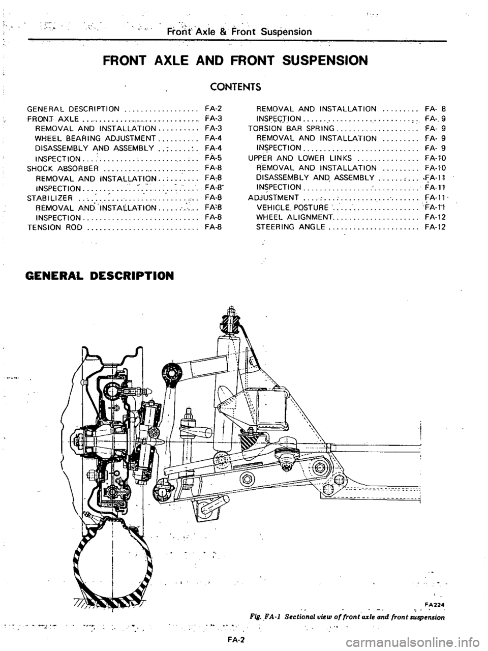
FA224
Fig
FA
j
SectionallJiew
of
fronta
xle
and
fron
t
suspension
FA
2
Page 352 of 537
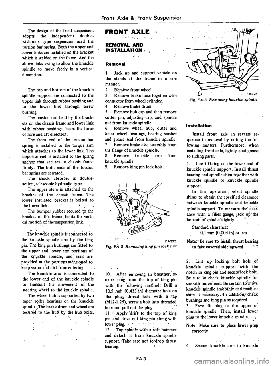
The
design
of
the
front
suspension
adopts
the
independent
double
wishbone
type
suspension
used
the
torsion
bar
spring
Both
the
upper
and
lower
links
are
installed
on
the
bracket
which
is
welded
on
the
frame
A
1d
the
above
links
swing
to
allow
the
knuckle
spindle
to
move
freely
in
a
vertical
dimension
The
top
and
bottom
of
the
knuckle
spindle
support
are
connected
to
the
upper
link
through
rubber
bushing
and
to
the
lower
lick
through
screw
bushing
The
tension
rod
held
by
the
brack
ets
on
the
chassis
frame
and
lower
lick
wiih
rubber
bushings
bears
the
force
of
fore
and
aft
direction
The
front
end
of
the
torsion
bar
spring
is
installed
to
the
torque
arm
which
attaches
to
the
lower
link
The
opposite
end
is
installed
to
the
spring
anchor
that
secures
to
chassis
frame
firmly
The
both
ends
of
the
torsion
bar
spring
are
serrated
The
shock
absorber
is
double
action
telescopic
hydraulic
type
The
upper
stem
is
attached
to
the
bracket
of
the
chassis
frame
The
lower
insulated
bracket
is
bolted
to
the
lower
lick
The
bumper
rubber
secured
to
the
bracket
Of
the
frame
limits
the
verti
cal
motion
of
the
suspension
lick
The
knuckle
spindle
is
connecied
to
the
k
ufkle
spindle
arm
by
the
king
pin
The
king
pin
bushings
are
fitted
to
the
upper
and
lower
arm
portIOns
of
the
knuckle
spindle
and
seals
are
provided
at
the
portions
mentioned
to
keep
water
and
dirt
from
enteri
g
The
knuckle
arm
is
connected
to
the
lower
end
of
the
knuckle
spindle
to
transmit
ttLe
movement
of
the
steering
wheel
to
the
knuckle
spindle
The
wheel
hub
is
supported
by
two
taper
roller
bearings
on
the
knuckle
spindle
Tlie
brake
drum
and
wheel
are
secured
to
ihe
hub
by
the
hub
bolts
Front
Axle
Front
Suspension
FRONT
AXLE
REMOVAL
AND
INSTALLATION
Removal
I
Jack
up
and
support
vehicle
on
the
stands
at
the
frame
in
a
safe
manner
2
Remove
front
wheel
3
Re
ove
brake
hose
together
with
connector
from
wheel
cylinder
4
Remove
brake
drum
S
Remove
hub
cap
and
then
remove
cotter
pin
adjusting
cap
and
spindle
nut
from
knuckle
spindle
6
Remove
wheel
hub
outer
and
inner
wheel
bearings
bearing
washer
and
grease
seal
from
knuckle
spindle
7
Remove
brake
disc
assembly
from
the
flange
of
knuckle
spindle
8
Remove
knuckle
arm
from
knuckle
spindle
9
Remove
king
pin
lock
bolt
FA225
Fig
FA
R
mol1ing
king
pin
loch
nut
10
After
removing
air
breather
re
move
plug
from
the
top
of
king
pin
with
the
following
method
Drill
a
10
5
mm
0
413
in
diameter
hole
on
the
plug
thread
hole
with
a
tap
M
12
1
2S
screw
a
bolt
into
threaded
hole
and
pull
out
the
plug
II
Apply
drift
to
the
top
of
king
pin
and
drive
out
king
pin
along
with
lower
plug
12
Tap
spindle
with
a
soft
haJnmer
and
detach
it
from
knuckle
spindle
support
Take
care
not
io
drop
thrust
bearing
FA
3
FA226
Fig
FA
3
R
moving
knuckle
piridle
Installation
Install
front
axle
in
reverse
se
quence
to
removal
by
noting
the
fol
lowing
matters
Furthermore
when
installing
front
axle
lightly
coat
grease
to
sliding
parts
I
Insert
O
ring
on
the
lower
end
of
knuckle
spindle
support
Install
thrust
bearing
and
spindle
shim
together
with
knuckle
spindle
to
knuckle
spindle
support
In
this
operation
select
spindle
shims
to
obtain
the
specified
clearance
between
knuckle
spindle
and
knuckle
spindle
support
To
measure
the
Clear
ance
with
a
filler
gauge
jack
up
the
bottom
of
spindle
slightly
Standard
clearance
0
1
mOl
0
004
in
or
less
Note
Be
sure
to
iristsll
thrust
bearing
to
face
coverea
side
upward
2
Line
up
locking
bolt
hole
of
knuckle
spindle
support
with
the
notch
in
king
pin
and
secure
lock
bolt
Be
sure
to
check
killJckle
spindle
for
smooth
movement
Be
certain
to
move
knuckie
spindle
smoothly
and
reailjust
shim
if
necessary
In
addition
check
bushings
and
king
pin
as
required
3
Press
fit
plug
to
the
upper
of
knuckle
spindle
Then
install
lower
plug
to
the
lower
knuckle
spindle
Note
Make
sure
to
place
lower
plug
conectly
4
Secure
knuckle
arm
to
knuckle
Page 357 of 537

SHOCK
ABSORBER
REMOVAL
AND
INSTAUATION
1
Raise
vehicle
on
a
hoist
or
stands
2
Remove
wheel
3
Hold
the
upper
stem
of
shock
absorber
and
remove
outs
washer
and
rubber
bushing
4
Remove
bolt
from
the
lower
end
of
shock
absorber
FA232
Fig
FA
13
Shock
absorber
S
Retain
lower
rubber
bushing
in
position
install
the
lower
end
of
shock
absorber
to
the
bracket
of
lower
link
and
torque
the
bolt
to
3
1
to
4
1
kg
m
23
to
30
ft
lb
Note
Insert
the
bolt
from
the
front
side
of
vehicle
6
Install
the
upper
end
of
shock
absorber
to
body
bracket
and
tighten
lock
n
Jt
to
the
specifjcations
Tightening
torque
1
6
to
2
2
kg
m
121016
ft
lb
INSPECTION
I
Check
shock
absorber
for
visible
defects
and
oil
leaks
Place
shock
absorber
vertically
in
a
vise
and
hand
stroke
shock
absorber
as
outlined
be
low
Extend
and
compress
shock
ab
sorber
as
faI
as
possible
travelling
as
long
as
possible
If
smooth
hydraulic
resistance
is
not
present
in
bqth
Iirection
replace
absorber
2
Replace
rubber
bushing
if
crack
or
deterioration
is
detected
Front
Axle
Front
Suspension
Specifications
for
shock
absorber
Model
Item
Piston
stroke
mm
in
Damping
force
kg
lb
0
3
m
sec
0
98
ft
sec
j
Rebound
Compression
STABILIZER
REMOVAL
AND
INSTAUATION
I
Raise
vehicle
on
a
hoist
or
stands
2
Remove
wheel
3
Loosen
secUring
nut
at
the
lower
link
side
of
stabilizer
4
Remove
bolt
securing
stabilizer
mounting
bracket
to
chassis
frame
Install
stabilizer
in
the
reverse
se
quence
to
removal
noting
the
follow
ing
instructions
S
Attach
stabilizer
mounting
brack
et
to
chassis
frame
tightening
bolt
to
1
6
to
2
2
kg
m
12
to
16
ft
lb
torque
6
Install
stabilizer
lower
link
side
to
connecting
rod
and
tighten
nut
to
the
specifications
as
shown
in
Figure
FA
14
Then
torque
lock
nut
toJ
6
to
2
2
kg
m
12
to
16
ft
lb
F
A233
Fig
FA
14
Stabilizer
detail
INSPECTION
Check
stabilizer
for
deformation
FA
S
All
models
110
4
3
76
168
38
84
and
rubber
bushings
for
crack
wear
and
deterioration
Replace
if
ne
cessary
TENSION
POD
REMOVAL
AND
INSTALLATION
I
Raise
vehicle
on
a
hoist
or
stands
2
Remove
wheel
3
Remove
nuts
CD
from
both
ends
of
tension
rod
4
Remove
bracket
bolt
@
from
the
front
end
of
tension
rod
and
remove
tension
rod
with
bracket
CD
@
f
A234
Fig
FA
15
Ten
ion
rod
Install
tension
rod
in
reverse
00
qunce
to
removal
noting
the
following
instructions
Page 359 of 537
UPPER
AND
LOWER
LINKS
REMOVAL
AND
INSTALLATION
Removal
I
Raise
vehicle
on
a
hoist
or
stands
2
Remove
wheel
and
brake
drum
as
an
assembly
3
Remove
wheel
hub
Refer
to
see
tion
Front
Axle
4
Loosen
bolts
retaining
brake
disc
to
knuckle
spindle
and
remove
brake
disc
5
Remove
knuckle
arm
torsion
bar
spimgJ
stabilizer
shock
absorber
and
tension
rod
in
t
ili
order
referring
the
related
sections
6
Remove
upper
fulcrum
bolt
se
curing
knuckle
spindle
support
to
upper
link
assembly
and
disassemble
them
7
Remove
upper
link
bushings
from
knuckle
spindle
support
8
Remove
screw
bushings
from
both
ends
of
lower
link
fulcrum
pin
9
Loosen
nut
at
lower
portion
of
knuckle
spindle
support
from
inside
and
pull
out
cotter
pin
retaining
ful
crum
pin
10
Pull
out
fulcrum
pin
with
drift
and
remove
knuckle
spindle
support
with
knuckle
spindle
from
lower
link
Then
detach
dust
cover
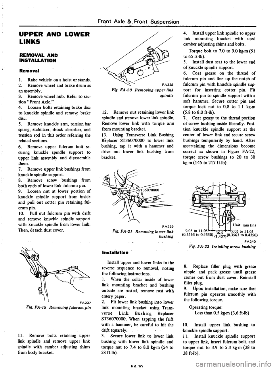
FA237
Fig
FA
19
Removing
fulcrum
pin
II
Remove
bolts
retaining
upper
link
spindle
and
remove
upper
link
spindle
with
camber
adjusting
shims
from
body
bracket
FrClnt
Axle
Front
Suspension
FA238
Fig
FA
20
Removing
upper
link
spindle
12
Remove
nut
retaining
lower
link
spindle
and
remove
lower
link
spindle
Remove
lower
link
with
torque
arm
from
mounting
bracket
13
Using
Transverse
Unk
Bushing
Replacer
ST36070000
to
lower
link
bushing
tap
it
with
a
hammer
and
drive
out
lower
link
bushing
from
bracket
F
A239
Fig
FA
21
Removing
lower
link
bushing
InstallatIon
Install
upper
and
lower
links
in
the
reverse
sequence
to
removal
noting
the
following
instructions
I
When
the
collar
inside
of
lower
link
mounting
bracket
and
bushing
outside
are
rusted
remove
rust
with
emery
paper
2
Fit
lower
link
bushing
into
lower
link
mounting
bracket
using
Trans
verse
Link
Bushing
Replacer
ST36070000
When
tapping
the
frift
with
a
hammer
be
careful
to
hit
the
drift
squarely
3
Secure
lower
link
to
lower
link
bushing
with
lower
link
spindle
and
torque
nut
to
74
to
8
0
kg
m
54
to
S8
ft
Ib
1
4
1n
4
Install
upper
link
spindle
to
upper
link
mounting
bracket
with
used
camber
adjusting
shims
and
bolts
Torque
bolt
to
7
0
to
9
0
kg
m
SI
to
6S
ft
lb
S
Install
dust
seat
to
the
lower
end
of
j
nuckle
spindle
support
6
Coat
grease
on
the
thread
of
fulcrum
pin
and
line
up
the
notch
of
fulcrum
pin
with
knuckle
spindle
sup
port
for
inserting
cotter
pin
Fit
fulcrum
pin
to
spindle
support
with
a
soft
hammer
Secure
cotter
pin
and
torque
lock
nut
to
0
8
to
1
1
kg
m
S
8
to
8
0
ft
lb
7
Coat
grease
to
the
tIuead
portion
of
screw
bushing
inside
liberally
Posi
tion
knuckle
spindle
support
at
the
center
of
lower
link
and
secure
screw
bushings
temporarily
by
hand
Mter
ascertaining
the
dimensions
become
correct
as
shown
in
Figure
F
A
22
torque
screw
bushings
to
20
to
30
kg
m
I4S
to
217
ft
lb
3
9
05
to
11
05
36
5
9
05
to
11
05
0
3563
to
0
4350
1
431
0
3563
to
0
4350
FA240
Fig
FA
22
In
tailing
IICrew
bu
hing
8
Replace
filler
plug
with
grease
nipple
and
pack
grease
until
grease
comes
out
from
dust
cover
Reinstall
filler
plug
9
Upon
installation
make
sure
that
fulcrum
pin
operates
smoothly
with
the
following
torque
Operating
torque
Less
than
0
5
kg
m
3
6
ft
lb
10
Install
upper
link
bushing
to
knuckle
spindle
support
I
I
Install
knuckle
spindle
support
to
upper
link
insert
fulcrum
bolt
and
torque
nut
to
3
9
to
S
3
kg
m
28
to
38
ft
lb