instrument cluster DATSUN PICK-UP 1977 Service Manual
[x] Cancel search | Manufacturer: DATSUN, Model Year: 1977, Model line: PICK-UP, Model: DATSUN PICK-UP 1977Pages: 537, PDF Size: 35.48 MB
Page 461 of 537

REMOVAL
AND
INSTALLATION
I
Disconnect
battery
ground
cable
2
Working
through
meter
openings
of
cluster
lid
remove
three
screws
retaining
cluster
lid
to
instrument
panel
3
From
underneath
instrument
panel
remove
one
screw
retaining
me
ter
assembly
to
lower
panel
of
instru
ment
4
Withdraw
cluster
lid
slightly
For
ccess
to
switches
knobs
etc
follow
the
procedures
given
in
each
section
5
From
behind
combination
meter
disconnect
speedometer
cable
at
speedometer
head
and
multiple
con
nector
instrume
nt
wire
assembly
from
printed
circuit
6
On
vehicle
with
clock
disconnect
wires
at
each
connection
on
meter
printed
circuit
7
Remove
four
screws
retaining
me
ter
assembly
to
cluster
lid
8
Remov
combination
meter
as
sembly
9
When
installing
combination
me
ter
assembly
follow
the
reverse
se
quence
of
removal
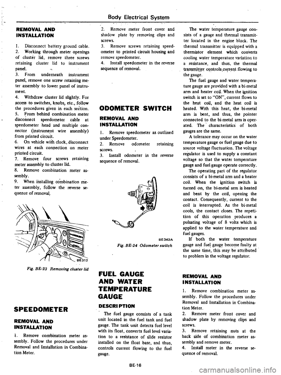
Fig
BE
23
Removing
eluster
lid
SPEEDOMETER
REMOVAL
AND
INSTALLATION
1
Remove
combination
meter
as
sembly
Follow
the
procedures
under
Removal
and
Installation
in
Combina
tion
Meter
Body
Electrical
System
2
Remove
meter
front
cover
and
shadow
plate
by
removing
clips
and
screws
3
Remove
screws
retaining
speed
ometer
to
printed
circuit
housing
and
remove
speedometer
4
Install
speedometer
in
the
reverse
sequence
of
removal
ODOMETER
SWITCH
REMOVAL
AND
INSTALLATION
I
Remove
speedometer
as
outlined
under
Speedometer
2
Remove
odometer
retaining
screws
3
Install
odometer
in
the
reverse
sequence
of
removal
BE342A
Fig
BE
24
Odometerswitch
FUEL
GAUGE
AND
WATER
TEMPERATURE
GAUGE
DESCRI
PTION
The
fuel
gauge
consists
of
a
tank
unit
located
in
the
fuel
tank
and
fuel
gauge
The
tank
unit
detects
fuel
level
with
its
float
converts
fuel
level
varia
tion
to
a
resistance
of
slide
resistor
installed
on
the
float
base
and
thus
controls
current
flowing
to
the
fuel
gauge
BE16
The
water
temperature
gauge
con
sists
of
a
gauge
and
thermal
transmit
ter
located
in
the
engine
block
The
thermal
transmitter
is
equipped
with
a
thermistor
element
which
converts
cooling
water
temperature
variation
to
a
resistance
and
thus
the
thermal
tr
t
c
rtrols
cUfTent
flowing
to
the
gauge
The
fuel
gauge
and
water
tempera
ture
gauge
are
provided
with
a
bi
metal
arm
and
heater
coil
When
the
ignition
switch
is
set
to
ON
current
flows
to
the
heat
coil
and
the
heat
coil
is
heated
With
this
heat
the
bi
metal
arm
is
bent
and
thus
the
pointer
connected
to
the
bi
metal
arm
is
oper
ated
The
characteristics
of
both
gauges
are
the
same
A
tolerance
may
occur
on
the
water
temperature
gauge
or
fuel
gauge
due
to
source
voltage
fluctuation
The
voltage
regulator
is
used
to
supply
a
constant
voltage
so
that
the
water
temperature
gauge
and
fuel
gauge
operate
correctly
The
operating
part
of
the
regulator
consists
of
a
bi
metal
arm
and
a
heater
coil
When
the
ignition
switch
is
turned
on
the
bi
metal
arm
is
heated
and
bent
by
the
coil
opening
the
contact
Consequently
current
to
the
coil
is
interrupted
As
the
bi
metal
cools
the
contact
closes
The
repeti
tion
of
this
operation
produces
a
pulsating
voltage
of
8
volts
which
is
applied
to
the
water
temperature
and
fuel
gauges
If
both
the
water
temperature
gauge
and
fuel
gauge
become
faulty
at
the
same
time
this
may
be
attributed
to
problem
in
the
voltage
regulator
REMOVAL
AND
INSTALLATION
1
Remove
combination
meter
as
sembly
Follow
the
procedures
under
Removal
and
Installation
in
Combina
tion
Meter
2
Remove
meter
front
cover
and
shadow
plate
by
removing
clips
and
screws
3
Remove
retaining
nuts
at
the
back
side
of
combination
meter
as
sembly
and
remove
meter
4
Install
meter
in
the
reverse
se
quence
of
removal
Page 470 of 537

RADIO
REMOVAL
AND
INSTALLATION
Radio
Removal
Pull
radio
knobs
offradio
control
shafts
Body
Electrical
System
2
Remove
radio
holding
nuts
and
washer
from
radio
control
shafts
3
Remove
radio
bezel
from
the
front
of
radio
4
From
under
instrument
panel
disconnect
antenna
cable
and
lead
wires
power
lead
and
speaker
lead
5
Remove
radio
from
instrument
panel
Installation
Fr
m
behind
instrument
panel
position
radio
to
instrument
panel
2
Install
radio
bezel
to
the
front
of
radio
3
Install
washers
and
nuts
on
radio
control
shafts
and
tighten
them
secure
ly
Then
install
control
knobs
4
Connect
antenna
cable
and
lead
wires
power
lead
and
speaker
lead
Antenna
and
antenna
cable
Removal
From
behind
instrument
panel
disconnect
antenna
cable
at
conne
tor
2
Remove
plug
on
antenna
base
and
remove
antenna
base
retaining
screw
3
Remove
antenna
and
cable
as
sembly
from
fr
ont
pillar
4
Unscrew
antenna
clip
from
front
pillar
if
necessary
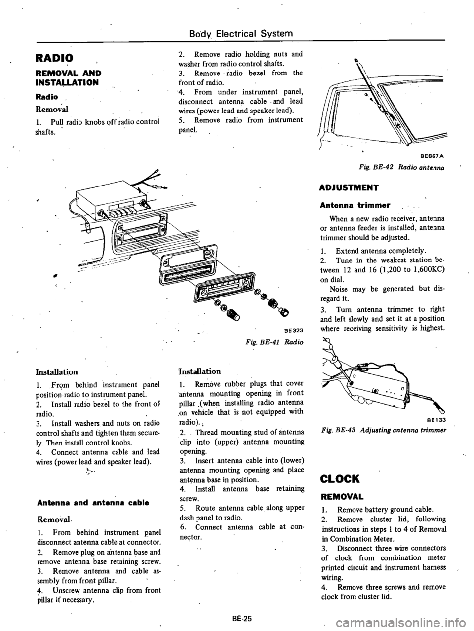
aE323
Fig
BE
41
Radio
Installation
Remove
rubber
plugs
that
cover
antenna
mounting
opening
in
front
pillar
when
installing
radio
antenna
on
vehicle
that
is
not
equipped
with
radio
2
Thread
mounting
stud
of
antenna
clip
into
upper
antenna
mountins
opening
3
Insert
antenna
cable
into
lower
antenna
mounting
opening
and
place
ant
nna
base
in
position
4
Install
antenna
base
retaining
screw
5
Route
antenna
cable
along
upper
dash
panel
to
radio
6
Connect
antenna
cable
at
con
nector
BE
25
t
BEB67
A
Fig
BE
42
Radio
ant
nna
ADJUSTMENT
Antenna
trimmer
When
a
new
radio
receiver
antenna
or
antenna
feeder
is
installed
antenna
trimmer
should
be
adjusted
Extend
antenna
completely
2
Tune
in
the
weakest
station
be
tween
12
and
16
1
200
to
1
600KC
on
dial
Noise
may
be
generated
but
dis
regard
it
3
Turn
antenna
trimmer
to
right
and
left
slowly
and
set
it
at
a
position
where
receiving
sensitivity
is
highest
SE133
Fig
BE
43
Adjwting
antenna
trimmer
CLOCK
REMOVAL
Remove
battery
ground
cable
2
Remove
cluster
lid
following
instructions
in
steps
I
to
4
of
Removal
in
Combination
Meter
3
Disconnect
three
wire
connectors
of
clock
from
combination
meter
printed
circuit
and
instrument
harnes
wiring
4
Remove
three
s
rews
and
remove
clock
from
cluster
lid
Page 471 of 537

INSTALLATION
I
Position
clock
to
cluster
lid
and
install
three
screws
2
Connect
three
wire
connectors
of
clock
to
each
connection
two
to
combination
meter
printed
circuit
one
to
instrument
h
ness
wiring
3
Install
cluster
lid
to
instrument
panel
4
Connect
battery
ground
cable
HEATER
DESCRIPTION
@
Body
Electrical
System
Fig
BE
44
Clock
1
Defroster
nozzle
L
U
2
Deflor
tcr
duct
L
R
3
Heater
control
4
Resistor
5
Heater
motor
6
Heater
case
7
Ventilator
knob
8
Heater
core
9
Conuol
cable
clip
10
Heater
cock
11
Defroster
duct
R
H
12
Defroster
nozzle
R
H
BE687B
Fig
BE
45
Heater
comtruction
BE
26